EP0163796B1 - Bohrkopf - Google Patents
Bohrkopf Download PDFInfo
- Publication number
- EP0163796B1 EP0163796B1 EP84440077A EP84440077A EP0163796B1 EP 0163796 B1 EP0163796 B1 EP 0163796B1 EP 84440077 A EP84440077 A EP 84440077A EP 84440077 A EP84440077 A EP 84440077A EP 0163796 B1 EP0163796 B1 EP 0163796B1
- Authority
- EP
- European Patent Office
- Prior art keywords
- screw
- piston
- boring head
- head according
- groove
- Prior art date
- Legal status (The legal status is an assumption and is not a legal conclusion. Google has not performed a legal analysis and makes no representation as to the accuracy of the status listed.)
- Expired
Links
Images


Classifications
-
- B—PERFORMING OPERATIONS; TRANSPORTING
- B23—MACHINE TOOLS; METAL-WORKING NOT OTHERWISE PROVIDED FOR
- B23B—TURNING; BORING
- B23B29/00—Holders for non-rotary cutting tools; Boring bars or boring heads; Accessories for tool holders
- B23B29/03—Boring heads
- B23B29/034—Boring heads with tools moving radially, e.g. for making chamfers or undercuttings
- B23B29/03403—Boring heads with tools moving radially, e.g. for making chamfers or undercuttings radially adjustable before starting manufacturing
- B23B29/03407—Boring heads with tools moving radially, e.g. for making chamfers or undercuttings radially adjustable before starting manufacturing by means of screws and nuts
- B23B29/0341—Cartridges
-
- B—PERFORMING OPERATIONS; TRANSPORTING
- B23—MACHINE TOOLS; METAL-WORKING NOT OTHERWISE PROVIDED FOR
- B23Q—DETAILS, COMPONENTS, OR ACCESSORIES FOR MACHINE TOOLS, e.g. ARRANGEMENTS FOR COPYING OR CONTROLLING; MACHINE TOOLS IN GENERAL CHARACTERISED BY THE CONSTRUCTION OF PARTICULAR DETAILS OR COMPONENTS; COMBINATIONS OR ASSOCIATIONS OF METAL-WORKING MACHINES, NOT DIRECTED TO A PARTICULAR RESULT
- B23Q1/00—Members which are comprised in the general build-up of a form of machine, particularly relatively large fixed members
- B23Q1/0009—Energy-transferring means or control lines for movable machine parts; Control panels or boxes; Control parts
- B23Q1/0018—Energy-transferring means or control lines for movable machine parts; Control panels or boxes; Control parts comprising hydraulic means
- B23Q1/0027—Energy-transferring means or control lines for movable machine parts; Control panels or boxes; Control parts comprising hydraulic means between moving parts between which an uninterrupted energy-transfer connection is maintained
- B23Q1/0036—Energy-transferring means or control lines for movable machine parts; Control panels or boxes; Control parts comprising hydraulic means between moving parts between which an uninterrupted energy-transfer connection is maintained one of those parts being a tool
-
- Y—GENERAL TAGGING OF NEW TECHNOLOGICAL DEVELOPMENTS; GENERAL TAGGING OF CROSS-SECTIONAL TECHNOLOGIES SPANNING OVER SEVERAL SECTIONS OF THE IPC; TECHNICAL SUBJECTS COVERED BY FORMER USPC CROSS-REFERENCE ART COLLECTIONS [XRACs] AND DIGESTS
- Y10—TECHNICAL SUBJECTS COVERED BY FORMER USPC
- Y10T—TECHNICAL SUBJECTS COVERED BY FORMER US CLASSIFICATION
- Y10T279/00—Chucks or sockets
- Y10T279/16—Longitudinal screw clamp
-
- Y—GENERAL TAGGING OF NEW TECHNOLOGICAL DEVELOPMENTS; GENERAL TAGGING OF CROSS-SECTIONAL TECHNOLOGIES SPANNING OVER SEVERAL SECTIONS OF THE IPC; TECHNICAL SUBJECTS COVERED BY FORMER USPC CROSS-REFERENCE ART COLLECTIONS [XRACs] AND DIGESTS
- Y10—TECHNICAL SUBJECTS COVERED BY FORMER USPC
- Y10T—TECHNICAL SUBJECTS COVERED BY FORMER US CLASSIFICATION
- Y10T408/00—Cutting by use of rotating axially moving tool
- Y10T408/83—Tool-support with means to move Tool relative to tool-support
- Y10T408/85—Tool-support with means to move Tool relative to tool-support to move radially
- Y10T408/858—Moving means including wedge, screw or cam
- Y10T408/8598—Screw extending perpendicular to tool-axis
-
- Y—GENERAL TAGGING OF NEW TECHNOLOGICAL DEVELOPMENTS; GENERAL TAGGING OF CROSS-SECTIONAL TECHNOLOGIES SPANNING OVER SEVERAL SECTIONS OF THE IPC; TECHNICAL SUBJECTS COVERED BY FORMER USPC CROSS-REFERENCE ART COLLECTIONS [XRACs] AND DIGESTS
- Y10—TECHNICAL SUBJECTS COVERED BY FORMER USPC
- Y10T—TECHNICAL SUBJECTS COVERED BY FORMER US CLASSIFICATION
- Y10T408/00—Cutting by use of rotating axially moving tool
- Y10T408/86—Tool-support with means to permit positioning of the Tool relative to support
-
- Y—GENERAL TAGGING OF NEW TECHNOLOGICAL DEVELOPMENTS; GENERAL TAGGING OF CROSS-SECTIONAL TECHNOLOGIES SPANNING OVER SEVERAL SECTIONS OF THE IPC; TECHNICAL SUBJECTS COVERED BY FORMER USPC CROSS-REFERENCE ART COLLECTIONS [XRACs] AND DIGESTS
- Y10—TECHNICAL SUBJECTS COVERED BY FORMER USPC
- Y10T—TECHNICAL SUBJECTS COVERED BY FORMER US CLASSIFICATION
- Y10T408/00—Cutting by use of rotating axially moving tool
- Y10T408/94—Tool-support
- Y10T408/95—Tool-support with tool-retaining means
- Y10T408/957—Tool adapter
Definitions
- the present invention relates to the field of machining by boring on conventional or numerically controlled machines, on machining centers or by means of flexible workshop equipment, and relates to a boring head.
- DE-A-2 411 394 discloses a crown type roughing head for mounting on a support fixed by two screws, a straight groove passing through the head.
- the wafer holders are constituted by two blocks the width of the groove, placed back to back, each fixed separately by two screws and tightened by two slots provided in the head. These two insert holders are, moreover, guided and mounted by means of teeth on the sides, without position indexing.
- FR-A-2 117 330 also discloses a boring bar, the cutting system of the insert holders and the adjustment system of which are two very complex separate elements.
- DE-A-3 044 862 describes boring tools with a cut having a monobloc body and whose adjusting screw of the tool is blocked in the body by means of a flat and a screw and the piston moved by means of this screw is retained in the device by means of a ball.
- This embodiment has a large operating clearance resulting in low precision of the piston drive device and rapid wear of said device.
- DE-C-885 591 discloses tool holders for parallel lathes which are intended to be mounted on the transverse carriage and which are used for fixing conventional lathing tools.
- DE-A-3 037 566 describes the design of an adjustment screw by means of a special piece preventing backlash and causing precision defects which are very detrimental to the parts to be machined.
- This document further describes tool holders or tools which are fixed in an inclined square of the piston of the adjusting screw and locked by means of a screw, which results in complicated machining of said piston.
- FR-A-2 117 330 describes a boring bar with two insert holders adjustable simultaneously by means of a single screw.
- the cutting system of these insert holders and the adjustment system are two very complex separate elements.
- the present invention aims to overcome these drawbacks.
- a boring head constituted by a body mounted on a support which is provided with a fixing tail, cylindrical of the modular or other type, or a tail adaptable directly on the machines, or of a tail with attachment to the Morse taper or to the American cone, or of a threaded tail TR, or other, to which it is rigidly fixed by a connecting screw, by an indexing device in all positions of the body relative to the support, and by an adjustable support and displacement assembly of the cutting tool in a direction perpendicular to the axis of the body.
- the boring head is essentially constituted by a body mounted on a support, by a device for indexing the body with respect to the support, and by a support and adjustable movement assembly for the cutting tool. perpendicular to the axis of the body.
- Figure 29 is a plan view of a drive post.
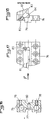
- the boring head is essentially constituted by a body 1 mounted on a support 2 which is provided with '' a fixing tail, cylindrical of the modular type or other, or a tail adaptable directly on the machines, or a tail with attachment to the Morse taper or to the American cone, or a TR threaded tail, or other , to which it is rigidly fixed by a connecting screw 3, by a device 4 for indexing in all positions of the body 1 relative to the support 2, and by a set 5 of support and adjustable movement of the cutting tool 6 in a direction perpendicular to the axis of the body 1.
- the device 4 for indexing the body 1 relative to the support 2 is constituted by a cylindrical stud 7 secured to the support 2 and capable of cooperating with holes 8 of corresponding diameter arranged at regular intervals on the rear face of the body 1, these holes 8 advantageously being twelve in number and offset by 30 °.
- This indexing mode allows adjustment of the angular position of the tool 6 in the best position, to within 15 °, when the spindle stops, to start or end the machining operations.
- Indexing can also be carried out by providing friction zones between the body 1 and the support 2, notches, teeth, or the like.
- the assembly 5 of support and adjustable displacement of the tool 6 is constituted by a piston 9 mounted to slide with very tight tolerances in a bore extending perpendicular to the axis of the body 1 near its front end, and actuated by means of a fine pitch micrometric screw 10, which, on the one hand, is provided with a wide head 11 with inclined flank, the center of which is provided with a hexagon for operating, and whose inclined flank has graduations cooperating with graduations provided on a flat 12 of the body 1, and, on the other hand, cooperates with a nut 13 secured to the piston 9 by gluing, a needle screw 14 ensuring its final tightening, this nut 13 being positioned in the piston 9 by means of a stop 15 simultaneously closing the cavity of the nut opposite to the screw 10 as well as a threaded hole used for fixing a tool holder 16 of the tool 6 in the form of a plate to the by means of a screw 17 and a washer 18.
- the nut 13 is not mounted tight so as not to undergo any deformation during its introduction into the piston 9, and the stop 15 serves, on the one hand, to support the nut 13, and, on the other hand, to avoid any entry of foreign body into the nut 13 and possible deterioration of the micrometric thread by such a body.
- the screw 10 is held in the body 1 by a resilient segment 19 fixed in a groove in the bore of the body 1, by a lock nut 20, and by a spacer 21, the thickness of which is slightly greater. than that of segment 19 in order to allow a mounting clearance of the screw 10 reduced to a minimum.
- a compressible washer of the Belleville type is inserted during assembly between the elastic segment 19 and the underside of the head of the screw. 10, with prior compression, preferably two-thirds, the thickness of the spacer 21 then being equal to that of the segment 19 increased by that of the compressed washer.
- the lubrication of the piston in its bore is carried out by means of a lubricator 26 whose outlet orifice is advantageously tangent to the bore at the level of the axis of the body 1, so that a small space is formed allowing the lubrication of the assembly.
- the piston 9 is provided with a groove 27 for housing the insert holder 16, which is kept applied during work against a clearance 28 provided in the free end of the body 1.
- the insert holder 16 can be fixed and centered in the piston 9, in any other way, namely by cross centering, or the like, and all types of insert can be mounted on said insert holder 16.
- the piston 9 can also be provided with a longitudinal clearance extending along a generator, provided with the footprint of the micrometric screw 10 , and intended to cooperate with the latter, which then has a larger diameter and extends tangentially to the piston 9.
- the boring head is constituted by a body 29 having at its rear part a tail of attachment, or the like, and at its front part an open housing having sides which are advantageously slightly inclined while widening in the direction of the tail, or sides parallel to the axis provided with grooves, or rectified guide teeth, or the like , by insert holders 30 and 31 housed in an adjustable manner in position in the body 29, by a screw for locking the insert holders 30 and 31 between the sides of the housing cooperating with a threaded hole 32 on one side of said housing and passing through the other side as well as a transverse groove of the insert holders, and by a device 33 for adjusting the insert holders.
- Such a boring head does not require indexing because it works with two tools, but must be more robust than the head described above. Likewise, the precision of the adjustment may be less, but the two insert holders must be able to be adjusted separately.
- the device 33 for adjusting the wafer holders 30 and 31 is constituted by two pins 34, 34 'each secured to a wafer holder 30 and 31 and penetrating through two parallel grooves 35 and 36 in two threaded holes 37 passing through the body 29 right through, one of the grooves 36 being open at one end (FIG. 5), and the other groove 35 being closed, and the transverse extension of said grooves is defined by the adjustment length of the insert holders 30 and 31, and by two pairs of screws 38 engaged in the threaded holes 37 in order to actuate the pins 34 and 34 'in displacement from the two sides of the holes 37.
- the closed groove 35 is provided for the insertion of the first insert holder 30 by the front face of the body 29, while the other groove 36 is intended to allow mounting of the second insert holder 31 by simple lateral fitting.
- the housing of the body 29 has, in known manner, at its bottom, along the sides, clearances intended to promote the machining of its walls.
- the locking screw is tightened in the hole 32 so as to pinch said insert holders, and the screws 38 are then applied on both sides against the rods 34 and 34 'respectively, holding the insert holders 30 and 31 perfectly in position.
- the movement of the wafer holders can also be carried out in other ways, for example by means of screws cooperating directly with the wafer holders, or the like.
- the body 29 has on each side a clearance 39 allowing an easy evacuation of the chips, as well as an orifice 40 for the arrival of cooling lubricant, which arrives through channels 41 connected to a rear central channel 42
- a clearance 39 allowing an easy evacuation of the chips, as well as an orifice 40 for the arrival of cooling lubricant, which arrives through channels 41 connected to a rear central channel 42
- Other arrangements of the lubrication channels are possible, in particular with the arrival of the lubricant at the bottom of the housing and passage through the insert holders, or else an ejection of the lubricant through a transverse hole perpendicular to the axis of the body, etc.
- a third insert holder can be mounted in place of one of the first two insert holders 30 and 31 and have a tool offset longitudinally relative to the other tool in order to carry out a delayed cut and a division of the width of the chips.
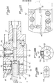
- the bore head is constituted, as shown in FIGS. 6 to 13 of the appended drawings, by a body 43 of identical design to that of the body 1 according to FIGS. 1 and 2 in that which concerns the adjustments, the piston 9, the fixing and the holders, by a sole 44 (FIGS. 10 to 13) for fixing and guiding the body 43 by means of screws 46, mounted with the possibility of indexing on an attachment (not shown), and by a device 45 for guided movement of the body 43.
- the sole 44 is provided with a bore 47 for centering on a corresponding hub with an attachment, known per se, this attachment being provided, moreover, with holes spaced regularly over a diameter and intended to cooperate with screws 48 for the fixing and indexing of the sole 44.
- the holes of the attachment will advantageously be spaced apart by 30 °.
- the sole 44 is provided on its face turned towards the body 43 with a longitudinal tongue 49 (FIG. 11) intended to cooperate with a corresponding centering groove 50 of the body 43, and allowing guided movement of said body 43 on the sole 44.
- the device 45 for guided movement of the body 43 consists of a driver 51 having two parallel flats (FIG. 6) and fixed in the body 43, in the axis of the groove 50, by a nut 52 provided with a transverse groove 53 intended to cooperate with the driver 51, guided in translation in a groove 54 in the sole 44, and driven by an adjustment screw 55, which is subjected in translation by a groove and ball mounting 56, and guided at its other end in a housing 57 of the sole.
- an additional threaded hole 62 oriented in the same direction as the holes 61, but preferably of smaller diameter, into which two screws 63 and 64 penetrate, one of which, 63, cooperates with a groove 65 of the body 43 and prevents the rotation of the corresponding rod 58 in its housing and forms a stop for the movement of the body 43 on the sole 44, while the other, 64, facing the sole 44, exceeds the face corresponding to the body 43 and cooperates with a corresponding groove 66 of the sole 44 for positioning the body 43 on said sole 44 during assembly, so that the threaded holes 61 of the pins 58 are aligned with those 67 and 67 'of the sole 44 ( Figure 10).
- the end stops for movement of the body 43 are formed, on the one hand, by the head of the screw 55, and, on the other hand, by the end of the groove 60, which cooperate in the extreme positions, respectively with the nut 52 and with a screw 46.
- the sole 44 is provided with at least two sets of nut 22 - adjusting screw 55 and holes for mounting and locking screws 46.
- the attachment of the sole to its attachment could also be achieved by a dovetail, by rectified toothing, or other.
- the guidance of the body 43 on the sole 44 could be achieved by other centering and guiding means.
- a counterweight is advantageously fixed on the other side of the sole 44 by means of the free holes for the mounting and locking screws.
- two screws 68 are provided (FIG. 9 ) having a part 68 'provided with a thread penetrating into a hole 61 of a rod 58 and a male part 68 "penetrating into a bore of the part 68' turned towards the sole 44, this part 68" being retained in its bore by a groove and ball connection 69 allowing pivoting of the part 68 "after tightening of the part 68 'in the rod 58 by means of two flats 70 of the part 68', and the part 68" is provided, near its free end of a conical hole 71, perpendicular to its axis, and into which enters a conical screw 72 fixed in the sole 44 and whose axis is offset from that of the hole 71, and in the extension of the hole 71 is fixed, with a slight offset towards the body 43,
- Figures 14 to 18 show another alternative embodiment of the invention, in which the body is in the form of an intermediate support block 75 ( Figures 14 to 16) or an upper support block 76 ( Figures 17 and 18) , the intermediate block 75 being fixedly adjustable on the sole 44, centered on the latter by means of a groove 77, and provided with threaded holes 78 for receiving the fixing screws of the upper block 76, which is guided on the block intermediate 75 by means of a tongue 79 cooperating with a groove 80 of said block 75, and which is provided with two additional housings of fixing screws allowing additional movement of the block 76 on the block 75.
- the intermediate block 75 being fixedly adjustable on the sole 44, centered on the latter by means of a groove 77, and provided with threaded holes 78 for receiving the fixing screws of the upper block 76, which is guided on the block intermediate 75 by means of a tongue 79 cooperating with a groove 80 of said block 75, and which is provided with two additional housings of fixing screws allowing additional movement of the block 76 on the block
- Heads conforming to those described above are particularly intended for large diameter rough bores and the head forming the upper block 76 uses commercially available cartridges 81 as platelet support, generally fixed by means of a biased thread. 82, and bearing on perpendicular faces 83 and 84, a screw 85 being provided for fine adjustment, from the rear.
- the micrometric screw with pitch end 10 which is used to actuate the piston 9 of the assembly 5 for support and adjustable movement of the tool 6, is maintained by means of an internal shoulder 86 machined in the housing bore of the piston 9 and a lock nut 20 ′, which is positioned so as to abut against the head 11 of the screw 10 and to be supported by an enlarged edge under the shoulder 86.
- a compressible washer 87 is supported, moreover, under the head 11 of the screw 10 and on the other face of the shoulder 86 to ensure, after a slight compression, a maintenance without play of the screw 10 in the body 1.
- the housing of the head 11 allows centering and positioning of the boring head for the rectification of the bore of the piston 9, and the precision of said boring heads is notably improved.
- the assembly 5 of support and adjustable movement of the tool 6 has a better seal against any penetration of liquid.
- a release groove 88 provided under the shoulder 86 allows the useful part of the piston housing bore 9 to be adjusted, and the positioning of the lock nut 20 ′ with its inverted head makes it possible to increase the length of the thread.
- the nut 13 of the screw 10 this nut 13 being flush with the face of the piston 9.
- the length of the thread of the nut 13 in contact with the screw 10 is increased, so that said thread can have a no finer resulting in improved precision and a simplified reading of the vernier formed by graduations provided on the side of the head 11 of the screw 10 and by a single line 89 on the body 1.
- the boring head is constituted by a body 90 mounted on a support 2 'and in which are mounted radially sliding, mutually parallel, a piston 91 for supporting a tool 6' by means of a bore 93 and a piston 9 'for actuating the piston 91 secured to the latter by means of a split pin 92, or the like, the movement of the piston 9 ′ being controlled by a fine pitch micrometric screw 10 provided with a wide head 11.
- the piston 9 'and its actuating means are similar to the piston 9 according to Figures 19 and 20 with regard to the adjustments and the maintenance of the screw 10 without play.
- the split pin 92 also ensures that the pistons 9 'and 91 are secured against undesired rotation, since the bore 93 for receiving the tool 6' must be rigorously fixed in the axis of the body 90, said tool 6 'being itself aligned with this axis.
- the tool 6 ' is fixed in the bore 93 of the support piston 91 by means of a ring 94 mounted in the bore 93 and secured in position by a needle screw 95, a shoulder 96 of this ring 94 protruding from the body 90 and protecting an opening 97 of the latter necessary for the movement of the tool, a split ring 98 which can surround, if necessary, the shank of the tool 6 ', and be clamped in the ring 94 by means of screws 99 mounted in threaded holes 100 of the piston 91 and passing through holes 101 of the ring 94.
- the piston 91 is locked in the working position by means of a pressure screw 102 fixed in the body 90 and acting perpendicular to the direction of movement on a flat 103 of the piston 91.
- the split ring 98 is provided with a thread 104 for its extraction from the ring 94.
- a boring head intended for roughing work its body 29, housing insert holders 30 and 31, is provided with two opposite pairs of needle screws 105 penetrating into threaded holes 106 of the body 29 and applying by their end in a groove 107 provided on the corresponding faces of the insert holders 30 and 31 ( Figures 23 and 24), and at least one insert holder is provided a threaded hole 108 extending obliquely to its application face in the bottom of the housing or a threaded hole 109 perpendicular to this face, a corresponding needle screw 110 or a flat-bottom screw 111 being mounted in the hole 108 or 109, (figures 25 and 26).
- the needle screws 105 make it possible to apply the rear faces of the holder 30 and 31 very precisely against the bottom of their housing in the body 29 so that their positioning is always very precisely ensured.
- the provision of a threaded hole 108 or 109 and a corresponding screw 110 or 111 makes it possible, by screwing said screw, after slightly releasing the corresponding screws 105 to lift and slightly pivot the plate in the housing, so that the cut of the tool can be offset slightly in height relative to the tool of the other insert.
- an additional insert holder with offset tool can be avoided.
- a channel 41 ′ which opens under the head of the screw 32 ′ for tightening the insert holders 30 and 31, the housing of this head having an opening 112 putting it in communication with the transverse grooves 113 of the insert holders 30 and 31, these grooves 113 forming a distribution chamber for the liquid and being each connected by two oblique holes 114 to outlet orifices 40 '.
- the channel 41 ' can be connected to a rear central feed channel 42 in a known manner by a channel 115 perpendicular to the axis.
- an upper support block 76 ′ (FIG. 27) is provided with a groove 116, the opening of which opens out from the interior side of the block, so that a tool insert 81, which is mounted therein, can be moved towards this side by means of its block adjusting screw 76 '. Thanks to this embodiment, it is possible to carry out turning works with the upper block 76 ′.
- a removable stud 117 mounted in the attachment by means of a countersunk screw and provided with a threaded hole 118 extending transversely of the tenon, and in which a screw 119 is tightened, which is supported by its end on one of the faces of the housing 120 of the support 2 , pushing, in reaction, the opposite face of the tenon 117 against the other face of the housing 120, a through hole 121 being provided on one side of the housing for the passage of the tool for operating the screw 119.
- connection of the support 2 with the drive device makes it possible to avoid the possible vibrations due to an unlocking of the self-tightening, in particular then of work with non-continuous cutting by shocks. Indeed, in such a case the repeated shocks cause, in the known devices, a continuous displacement of the post in both directions, in its housing, causing a loosening of the locking screws.
- the post has a width equal to that of the housing of the support 2 and the spherical housings of the tail of the latter are slightly offset relative to their corresponding clamping screw.
- the tightening of one or the other screw immediately causes a slight rotation of the support 2, which has the effect of strongly applying the corresponding face of the stud against the face of its housing.
- Such an embodiment is particularly suitable for carrying out very hard work.
Landscapes
- Engineering & Computer Science (AREA)
- Mechanical Engineering (AREA)
- Cutting Tools, Boring Holders, And Turrets (AREA)
Claims (28)
Priority Applications (1)
| Application Number | Priority Date | Filing Date | Title |
|---|---|---|---|
| AT84440077T ATE47547T1 (de) | 1984-04-24 | 1984-12-28 | Bohrkopf. |
Applications Claiming Priority (4)
| Application Number | Priority Date | Filing Date | Title |
|---|---|---|---|
| FR8406903 | 1984-04-24 | ||
| FR8406903A FR2563132B1 (fr) | 1984-04-24 | 1984-04-24 | Tete d'alesage |
| FR8414315A FR2570008B2 (fr) | 1984-04-24 | 1984-09-13 | Tete d'alesage |
| FR8414315 | 1984-09-13 |
Publications (2)
| Publication Number | Publication Date |
|---|---|
| EP0163796A1 EP0163796A1 (de) | 1985-12-11 |
| EP0163796B1 true EP0163796B1 (de) | 1989-10-25 |
Family
ID=26223942
Family Applications (1)
| Application Number | Title | Priority Date | Filing Date |
|---|---|---|---|
| EP84440077A Expired EP0163796B1 (de) | 1984-04-24 | 1984-12-28 | Bohrkopf |
Country Status (4)
| Country | Link |
|---|---|
| US (1) | US4784536A (de) |
| EP (1) | EP0163796B1 (de) |
| DE (1) | DE3480270D1 (de) |
| FR (1) | FR2570008B2 (de) |
Families Citing this family (18)
| Publication number | Priority date | Publication date | Assignee | Title |
|---|---|---|---|---|
| ATE73027T1 (de) * | 1988-05-06 | 1992-03-15 | Emile Pfalzgraf | Vorrichtung zur befestigung von werkzeughaltern und werkzeugen mit konischen und planen tragflaechen, insbesondere fuer bearbeitungszentren mit automatischen oder manuellen werkzeugwechslern. |
| DE8814843U1 (de) * | 1988-10-17 | 1989-02-02 | Mas Vertriebsgesellschaft Fuer Zerspanungstechnik Mbh, 7250 Leonberg, De | |
| FR2641996A2 (fr) * | 1988-11-15 | 1990-07-27 | Pfalzgraf Emile Epb Sa | Dispositif de montage a queue conique, en particulier au cone 7/24e, a application cone et face pour attachements, porte-outils et outils |
| FR2657284B1 (fr) * | 1990-01-23 | 1992-04-30 | Pfalzgraf Sa Epb Emile | Dispositif de montage a queue conique, en particulier au cone 7/24eme, a application cone et face pour attachements, porte-outils et outils. |
| FR2662103B1 (fr) * | 1990-05-15 | 1995-04-07 | Epb Emile Pfalzgraf Sa | Tete a aleser. |
| EP0478239A1 (de) * | 1990-09-24 | 1992-04-01 | Lohner, KLaus | Bohrkopfpatrone und Patroneneinbaumöglichkeit |
| US5396693A (en) * | 1990-12-12 | 1995-03-14 | Parlec, Inc. | Precision boring tool and method of producing tool cartridge |
| US5054970A (en) * | 1991-02-25 | 1991-10-08 | Parlec, Inc. | Boring head with a pair of axially and radially individually adjustable cutting elements |
| US5193950A (en) * | 1991-08-26 | 1993-03-16 | Gte Valenite Corporation | Adjustable boring head |
| DE4330822A1 (de) * | 1993-09-13 | 1995-03-16 | Komet Stahlhalter Werkzeug | Werkzeugkopf für den Einsatz in Werkzeugmaschinen |
| CH690358A5 (de) * | 1996-02-22 | 2000-08-15 | Kaiser Heinz Ag | Verbindung zwischen einem Schneidenhalter und einem Werkzeugträger eines Ausdrehkopfes. |
| US6510620B2 (en) | 2000-04-15 | 2003-01-28 | Robert G. Bender | Tool and method for the precision boring of holes |
| FR2813812B1 (fr) * | 2000-09-11 | 2002-11-29 | Epb | Tete a aleser |
| DE10052016A1 (de) * | 2000-10-20 | 2002-05-08 | Horn P Hartmetall Werkzeugfab | Rotierendes Werkzeug, insbesondere Fräswerkzeug |
| DE102005045752A1 (de) * | 2005-09-23 | 2007-03-29 | Sandvik Intellectual Property Ab | Zerspanungswerkzeug mit Feinstverstellung |
| FR2960805B1 (fr) * | 2010-06-07 | 2013-04-26 | Seco E P B | Outil a aleser sur semelle |
| EP4299220A1 (de) * | 2022-06-28 | 2024-01-03 | Seco Tools AB | Bohrkopf und bohrwerkzeuganordnung |
| CN115996520B (zh) * | 2023-03-22 | 2023-06-02 | 遂宁睿杰兴科技有限公司 | 一种印制电路板锥形孔加工钻头 |
Family Cites Families (30)
| Publication number | Priority date | Publication date | Assignee | Title |
|---|---|---|---|---|
| GB510851A (en) * | 1939-01-14 | 1939-08-09 | Diamond Tools Ltd | Improvements in holders for diamond tools |
| US2282919A (en) * | 1940-12-30 | 1942-05-12 | Edward A Zempel | Boring bar |
| DE885951C (de) * | 1941-11-18 | 1953-08-10 | Ernst Hauer & Co | Mehrfachstahlhalter |
| US2398491A (en) * | 1942-12-18 | 1946-04-16 | Bell Nicholas | Boring head |
| DE815754C (de) * | 1949-06-18 | 1951-10-04 | Goeckel Gmbh Maschf G | Teilkopf |
| US2676809A (en) * | 1953-06-18 | 1954-04-27 | Frederick H Smith | Toolholder bushing |
| US3005365A (en) * | 1958-05-19 | 1961-10-24 | Carl A Billman | Boring bar |
| US3067636A (en) * | 1959-04-30 | 1962-12-11 | Breuning Robert | Boring head |
| US3069932A (en) * | 1959-06-08 | 1962-12-25 | De Vlieg Machine Co | Blade facing tool |
| FR1266970A (fr) * | 1960-09-08 | 1961-07-17 | Unité d'usinage | |
| US2998736A (en) * | 1960-11-04 | 1961-09-05 | Valeron Corp | Tool mounting for boring bar |
| US3293727A (en) * | 1961-04-12 | 1966-12-27 | Bilt Rite Tool & Machine Co | Cutting tool |
| US3364800A (en) * | 1965-05-07 | 1968-01-23 | Erickson Tool Co | Mist coolant spade drill |
| GB1309732A (en) * | 1969-05-27 | 1973-03-14 | Herbert Ltd A | Cutting tool holder |
| US3635572A (en) * | 1970-05-18 | 1972-01-18 | Valeron Corp | Boring bar adjustment |
| CH540734A (de) * | 1970-11-27 | 1973-08-31 | Gildemeister Devlieg System | Bohrwerkzeug mit zwei verstellbaren Schneidplattenhaltern |
| DE2411394C3 (de) * | 1974-03-09 | 1980-09-11 | Grueko Konstruktionen Gmbh, 7926 Boehmenkirch | Bohrkopf |
| HU169154B (de) * | 1974-05-03 | 1976-10-28 | ||
| CH593749A5 (de) * | 1974-11-15 | 1977-12-15 | Komet Stahlhalter Werkzeug | |
| CH616098A5 (en) * | 1977-03-31 | 1980-03-14 | Benno Koch | Tool head for boring |
| CH627676A5 (de) * | 1978-05-11 | 1982-01-29 | Kaiser Heinz Ag | Zweischneider-ausdrehkopf. |
| CH641706A5 (de) * | 1979-12-04 | 1984-03-15 | Kaiser Heinz Ag | Ausdrehkopf mit feinverstellmechanismus. |
| DD147918B1 (de) * | 1979-12-07 | 1984-03-14 | Ursula Hilpert | Einschneidiges ausbohrwerkzeug |
| DE3049026A1 (de) * | 1979-12-29 | 1981-09-17 | Kyoritsu Seiki Corp., Utsunomiya, Tochigi | Werkzeugkopf |
| CH650711A5 (en) * | 1980-06-13 | 1985-08-15 | Benno Koch | Boring tool head |
| US4396319A (en) * | 1980-12-22 | 1983-08-02 | Erickson Tool Company | Adjustable insert cartridge |
| DE3204923A1 (de) * | 1982-02-12 | 1983-08-25 | Stellram GmbH, 6056 Heusenstamm | Werkzeug zum aufbohren von bohrungen |
| DE3204922A1 (de) * | 1982-02-12 | 1983-08-25 | Stellram GmbH, 6056 Heusenstamm | Werkzeug zum aufbohren von bohrungen |
| DE3237128A1 (de) * | 1982-10-07 | 1984-04-12 | Wilhelm Fette Gmbh, 2053 Schwarzenbek | Kombinationswerkzeug |
| DE3312990A1 (de) * | 1983-04-12 | 1984-10-18 | Heinz Wendel Präzisionsmechanik-Werkzeugbau, 7240 Horb | Ausdrehwerkzeug |
-
1984
- 1984-09-13 FR FR8414315A patent/FR2570008B2/fr not_active Expired
- 1984-12-28 DE DE8484440077T patent/DE3480270D1/de not_active Expired
- 1984-12-28 EP EP84440077A patent/EP0163796B1/de not_active Expired
-
1985
- 1985-04-17 US US06/724,297 patent/US4784536A/en not_active Expired - Lifetime
Also Published As
| Publication number | Publication date |
|---|---|
| EP0163796A1 (de) | 1985-12-11 |
| US4784536A (en) | 1988-11-15 |
| FR2570008B2 (fr) | 1988-08-05 |
| FR2570008A2 (fr) | 1986-03-14 |
| DE3480270D1 (en) | 1989-11-30 |
Similar Documents
| Publication | Publication Date | Title |
|---|---|---|
| EP0163796B1 (de) | Bohrkopf | |
| EP0317682B1 (de) | Zusammenbauvorrichtung für einen Kegelschaft, insbesondere für 7/24 Kegelschäfte, verwendet für Anbauvorrichtungen, Werkzeughalter und Werkzeuge | |
| EP1796871B9 (de) | Vorrichtung zum einspannen eines werkzeugeinsatzes in eine schleifmaschine | |
| EP1784271B1 (de) | Bohrkopf | |
| EP2576108B1 (de) | Ausdrehkopf auf einem balken | |
| EP0340369B1 (de) | Vorrichtung zur Befestigung von Werkzeughaltern und Werkzeugen mit konischen und planen Tragflächen, insbesondere für Bearbeitungszentren mit automatischen oder manuellen Werkzeugwechslern | |
| EP0210083B1 (de) | Schnellwechselsystem für Spannbacken an einer Werkzeugmaschine | |
| EP0823268B1 (de) | Schuhbindungsvorrichtung für ein Gleitbrett | |
| EP0356281B1 (de) | Spannzange, adaptierbar an ein Werkzeugmaschinenfutter | |
| CA1289740C (fr) | Dispositif de montage a queue conique, en particulier au cone 7/24, a application cone et face pour attachements, porte-outils et outils | |
| EP1317329B1 (de) | Bohrkopf | |
| EP0373086A1 (de) | Montagevorrichtung für Kegelschäfte, insbesondere mit 7/24-Kegel für Anordnungen, Werkzeughalter und Werkzeuge | |
| EP2731744A1 (de) | Vorrichtung zum halten von mechanischen teilen | |
| EP0438952A1 (de) | Aufnahme-Vorrichtung für Werkzeugträger und Werkzeuge mit konischem Schaft, insbesondere mit 7/24. Konus und Auflagen für Konus und Endfläche | |
| FR2563132A1 (fr) | Tete d'alesage | |
| CH685680A5 (fr) | Outil de coupe à plaquettes amovibles. | |
| CH688794A5 (fr) | Outil de coupe à plaquettes amovibles. | |
| EP1011901B1 (de) | Drehkopf mit mindestens zwei werkzeugen | |
| EP0230200B1 (de) | Axiale Regelungsvorrichtung von Werkzeugen in Werkzeugmaschinen | |
| EP0949030A1 (de) | Drehendes Schneidwerkzeug | |
| EP0234171A1 (de) | Ausdrehkopf | |
| FR2837732A1 (fr) | Fraise a plaquettes de coupe amovible pour usinage a tres grande vitesse | |
| FR2542230A1 (fr) | Outil tubulaire pour l'usinage, et tete d'usinage ainsi equipee | |
| FR2638991A1 (fr) | Dispositif de montage a queue conique, en particulier au cone 7/24, a application cone et face pour attachements, porte-outils et outils | |
| FR2616367A1 (fr) | Perfectionnements aux fraises d'usinage |
Legal Events
| Date | Code | Title | Description |
|---|---|---|---|
| PUAI | Public reference made under article 153(3) epc to a published international application that has entered the european phase |
Free format text: ORIGINAL CODE: 0009012 |
|
| AK | Designated contracting states |
Designated state(s): AT BE CH DE GB IT LI LU NL SE |
|
| 17P | Request for examination filed |
Effective date: 19860113 |
|
| 17Q | First examination report despatched |
Effective date: 19870410 |
|
| GRAA | (expected) grant |
Free format text: ORIGINAL CODE: 0009210 |
|
| AK | Designated contracting states |
Kind code of ref document: B1 Designated state(s): AT BE CH DE GB IT LI LU NL SE |
|
| PG25 | Lapsed in a contracting state [announced via postgrant information from national office to epo] |
Ref country code: SE Effective date: 19891025 |
|
| REF | Corresponds to: |
Ref document number: 47547 Country of ref document: AT Date of ref document: 19891115 Kind code of ref document: T |
|
| REF | Corresponds to: |
Ref document number: 3480270 Country of ref document: DE Date of ref document: 19891130 |
|
| ITF | It: translation for a ep patent filed |
Owner name: STUDIO INGG. FISCHETTI & WEBER |
|
| GBT | Gb: translation of ep patent filed (gb section 77(6)(a)/1977) | ||
| PLBE | No opposition filed within time limit |
Free format text: ORIGINAL CODE: 0009261 |
|
| STAA | Information on the status of an ep patent application or granted ep patent |
Free format text: STATUS: NO OPPOSITION FILED WITHIN TIME LIMIT |
|
| 26N | No opposition filed | ||
| ITTA | It: last paid annual fee | ||
| EPTA | Lu: last paid annual fee | ||
| REG | Reference to a national code |
Ref country code: CH Ref legal event code: PUE Owner name: EMILE PFALZGRAF TRANSFER- E.P.B. EMILE PFALZGRAF ( |
|
| REG | Reference to a national code |
Ref country code: GB Ref legal event code: 732E |
|
| NLS | Nl: assignments of ep-patents |
Owner name: E.P.B. EMILE PFALZGRAF (SOCIETE ANONYME) |
|
| REG | Reference to a national code |
Ref country code: GB Ref legal event code: IF02 |
|
| PGFP | Annual fee paid to national office [announced via postgrant information from national office to epo] |
Ref country code: GB Payment date: 20031219 Year of fee payment: 20 |
|
| PGFP | Annual fee paid to national office [announced via postgrant information from national office to epo] |
Ref country code: AT Payment date: 20031222 Year of fee payment: 20 |
|
| PGFP | Annual fee paid to national office [announced via postgrant information from national office to epo] |
Ref country code: LU Payment date: 20031229 Year of fee payment: 20 |
|
| PGFP | Annual fee paid to national office [announced via postgrant information from national office to epo] |
Ref country code: NL Payment date: 20031231 Year of fee payment: 20 Ref country code: BE Payment date: 20031231 Year of fee payment: 20 |
|
| PGFP | Annual fee paid to national office [announced via postgrant information from national office to epo] |
Ref country code: DE Payment date: 20040127 Year of fee payment: 20 |
|
| PGFP | Annual fee paid to national office [announced via postgrant information from national office to epo] |
Ref country code: CH Payment date: 20040329 Year of fee payment: 20 |
|
| PG25 | Lapsed in a contracting state [announced via postgrant information from national office to epo] |
Ref country code: LI Free format text: LAPSE BECAUSE OF EXPIRATION OF PROTECTION Effective date: 20041227 Ref country code: GB Free format text: LAPSE BECAUSE OF EXPIRATION OF PROTECTION Effective date: 20041227 Ref country code: CH Free format text: LAPSE BECAUSE OF EXPIRATION OF PROTECTION Effective date: 20041227 |
|
| PG25 | Lapsed in a contracting state [announced via postgrant information from national office to epo] |
Ref country code: NL Free format text: LAPSE BECAUSE OF EXPIRATION OF PROTECTION Effective date: 20041228 Ref country code: LU Free format text: LAPSE BECAUSE OF EXPIRATION OF PROTECTION Effective date: 20041228 |
|
| BE20 | Be: patent expired |
Owner name: E.P.B. EMILE *PFALZGRAF Effective date: 20041228 |
|
| REG | Reference to a national code |
Ref country code: GB Ref legal event code: PE20 |
|
| REG | Reference to a national code |
Ref country code: CH Ref legal event code: PL |
|
| NLV7 | Nl: ceased due to reaching the maximum lifetime of a patent |
Effective date: 20041228 |