EP0438952A1 - Aufnahme-Vorrichtung für Werkzeugträger und Werkzeuge mit konischem Schaft, insbesondere mit 7/24. Konus und Auflagen für Konus und Endfläche - Google Patents
Aufnahme-Vorrichtung für Werkzeugträger und Werkzeuge mit konischem Schaft, insbesondere mit 7/24. Konus und Auflagen für Konus und Endfläche Download PDFInfo
- Publication number
- EP0438952A1 EP0438952A1 EP90440128A EP90440128A EP0438952A1 EP 0438952 A1 EP0438952 A1 EP 0438952A1 EP 90440128 A EP90440128 A EP 90440128A EP 90440128 A EP90440128 A EP 90440128A EP 0438952 A1 EP0438952 A1 EP 0438952A1
- Authority
- EP
- European Patent Office
- Prior art keywords
- cone
- front part
- spindle
- face
- balls
- Prior art date
- Legal status (The legal status is an assumption and is not a legal conclusion. Google has not performed a legal analysis and makes no representation as to the accuracy of the status listed.)
- Withdrawn
Links
Images


Classifications
-
- B—PERFORMING OPERATIONS; TRANSPORTING
- B23—MACHINE TOOLS; METAL-WORKING NOT OTHERWISE PROVIDED FOR
- B23B—TURNING; BORING
- B23B31/00—Chucks; Expansion mandrels; Adaptations thereof for remote control
- B23B31/006—Conical shanks of tools
-
- B—PERFORMING OPERATIONS; TRANSPORTING
- B23—MACHINE TOOLS; METAL-WORKING NOT OTHERWISE PROVIDED FOR
- B23B—TURNING; BORING
- B23B2231/00—Details of chucks, toolholder shanks or tool shanks
- B23B2231/04—Adapters
-
- Y—GENERAL TAGGING OF NEW TECHNOLOGICAL DEVELOPMENTS; GENERAL TAGGING OF CROSS-SECTIONAL TECHNOLOGIES SPANNING OVER SEVERAL SECTIONS OF THE IPC; TECHNICAL SUBJECTS COVERED BY FORMER USPC CROSS-REFERENCE ART COLLECTIONS [XRACs] AND DIGESTS
- Y10—TECHNICAL SUBJECTS COVERED BY FORMER USPC
- Y10T—TECHNICAL SUBJECTS COVERED BY FORMER US CLASSIFICATION
- Y10T279/00—Chucks or sockets
- Y10T279/17—Socket type
- Y10T279/17666—Radially reciprocating jaws
- Y10T279/17692—Moving-cam actuator
- Y10T279/17743—Reciprocating cam sleeve
- Y10T279/17752—Ball or roller jaws
-
- Y—GENERAL TAGGING OF NEW TECHNOLOGICAL DEVELOPMENTS; GENERAL TAGGING OF CROSS-SECTIONAL TECHNOLOGIES SPANNING OVER SEVERAL SECTIONS OF THE IPC; TECHNICAL SUBJECTS COVERED BY FORMER USPC CROSS-REFERENCE ART COLLECTIONS [XRACs] AND DIGESTS
- Y10—TECHNICAL SUBJECTS COVERED BY FORMER USPC
- Y10T—TECHNICAL SUBJECTS COVERED BY FORMER US CLASSIFICATION
- Y10T408/00—Cutting by use of rotating axially moving tool
- Y10T408/94—Tool-support
- Y10T408/95—Tool-support with tool-retaining means
-
- Y—GENERAL TAGGING OF NEW TECHNOLOGICAL DEVELOPMENTS; GENERAL TAGGING OF CROSS-SECTIONAL TECHNOLOGIES SPANNING OVER SEVERAL SECTIONS OF THE IPC; TECHNICAL SUBJECTS COVERED BY FORMER USPC CROSS-REFERENCE ART COLLECTIONS [XRACs] AND DIGESTS
- Y10—TECHNICAL SUBJECTS COVERED BY FORMER USPC
- Y10T—TECHNICAL SUBJECTS COVERED BY FORMER US CLASSIFICATION
- Y10T409/00—Gear cutting, milling, or planing
- Y10T409/30—Milling
- Y10T409/30952—Milling with cutter holder
Definitions
- the present invention relates to the field of accessories for machine tools, numerically controlled, machining centers, cells and flexible workshops, and relates to a mounting device with a conical shank, in particular to the 7 / 24th cone, with cone application. and face for attachments, tool holders and tools.
- the critical point and the weakness of the current fixings are most often located at the spindle outlet, which is a weakening point for all tool holders or tools, the latter having to respect a specific diameter of the tool, which is the large diameter of the end of the cone connected by a short cylindrical portion to the flange.
- the same problem also arises, but less crucially, for the attachment of tools to the 7 / 24th cone on lathes.
- a mounting device with a conical tail has also been proposed, in particular with the 7 / 24th cone, with cone and face application for attachments, tool holders and tools, which essentially consists of a cone for introduction into the spindle, by a front part centered in the cone and provided with the application flange against the face of the spindle, by a cone assembly pull tab and the front part, by an elastic assembly for pressing the cone in the spindle , mounted in compression between the cone and the front part, and by a means for adjusting said pressure assembly.
- the present invention aims to overcome these drawbacks.
- a mounting device with a conical shank in particular with a 7 / 24th cone, with cone and face application for attachments, tool holders and tools, essentially constituted by a cone for mounting in a spindle, by a front part centered in the cone and provided with an application collar by its rear face against the front face of the spindle, and by a connecting rod for the cone and the front part by means of a threaded intermediate piece , on which rests an elastic assembly formed of Belleville washers intended to apply the cone in the spindle in the locked position and mounted in compression between said cone and the front part, characterized in that it is provided with a locking of the mutual position of the cone and of the front part, in the mounting position in the spindle with application of the flange against the face of said spindle, by clamping at least two balls between said cone and by tie before.
- the mounting device with a conical tail in particular to the 7 / 24th cone, with cone and face application for attachments, tool holders and tools, essentially constituted by a cone 1 for mounting in a spindle 2, by a front part 3 centered in the cone 1 and provided with a flange 4 for application by its rear face against the front face of the spindle 2, and by a pull tab 5 for assembling the cone 1 and the front part 3 by means of a threaded intermediate piece 6, on which rests an elastic assembly 7 formed of Belleville washers intended to apply the cone 1 in the spindle 2 in the locking position and mounted in compression between said cone 1 and the front part 3, characterized in that it is provided with a device 8 for locking the mutual position of the cone 1 and the front part 3, in mounting position in the br hole 2 with application of the collar 4 against the face of said pin 2, by clamping at least two balls 9 between said cone 1 and front part 3.
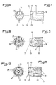
- the device 8 for locking the mutual position of the cone 1 and the front part 3 is advantageously constituted by a cylindrical locking piece 10 housed in the front part 3, facing the pull tab 5 and having a frustoconical part 11 cooperating with at least two balls 9, preferably with three balls 9, on the side facing the pull tab 5, said balls 9 being positioned at regular intervals in slots 12 of the front part 3 and cooperating with corresponding housings 13 or a corresponding circular groove (not shown) of the cone 1, said part 10 being loaded by at least one spring 14 disposed in at least one housing 15 in its rear part and held in said housing by means of a closing cover 16 (FIG. 1) or of a stop 17 or 18 ( Figures 12 and 13) for adjusting the pressure of the spring (s).
- the number of balls 9 is not immutable and it is possible to provide more than three balls, the lights 12 and the corresponding housings 13 then being the same number.
- the balls 9 can be provided in large numbers and cooperate with a corresponding number of housings 13 or with a circular groove in the cone 1.
- These slots 12 are better visible in FIGS. 2 and 3 appended drawings, which represent alternative embodiments of the front part 3, which may also include, instead of a single centering diameter in the cone 1, as shown in FIGS. 1 to 3, two or more centering diameters, the largest diameter always being located towards the flange 4.
- the locking piece 10 is provided with a single housing 15 (FIGS. 4 to 7) for receiving a single spring 14 or several housings 19 arranged in barrel ( Figures 8 to 11) for receiving several springs 20.
- This locking piece 10 is further provided, on the one hand, on its cylindrical part, at regular intervals, preferably at 60 °, with longitudinal indexing grooves 21 intended to cooperate with a ball (not shown) housed in a radial bore 22 of the front part 3, at the level of the flange 4 and in the middle of the groove 23 of the latter and loaded by a spring (not shown), the tension of which is adjusted by means of a screw housed in a end thread 24 of the bore 22 (FIGS. 2 and 3) and, on the other hand, on its frustoconical part 11, at regular intervals, preferably at 120 °, recesses 25 for releasing the balls 9 during assembly of the device ( Figures 4 to 11).
- the frustoconical part 11 of the locking piece 10 can also be provided, at regular intervals, preferably between the recesses 25, with longitudinal grooves 26 with a spherical bottom, the radius of curvature of which is equal to the radius of the balls 9.
- These grooves 26 allow a greater application of the balls 9 on the parts 10, during the locking of the mutual position of the cone 1 and of the front part 3, that in the embodiment according to FIGS. 4, 5, 8 and 9.
- the application of the balls is carried out in an arc, while in the other case, it is punctual.
- the threaded intermediate piece 6 is advantageously provided, at the end of its internal housing facing the locking piece 10, with a stopper 27 for the pull tab 5, in the form of an elastic ring penetrating into a circular groove provided at the end of said housing.
- the stops 17 and 18 for adjusting the pressure of the single spring 14 or of the multiple springs 20 are intended to be introduced, either one, 17, in a housing 28 of the front part 3 with the possibility of adjustment in displacement by means of a screw cooperating with a tapping 29 of this front part 3, provided on the side opposite to the housing of the part 10 (FIG. 2), or the other, 18, in a tapping 30 of the front part 3, extending the housing of the piece 10 on the side opposite to the pull tab 5 ( Figure 3).
- the pressure can be adjusted directly by means of the stopper 18 by a corresponding screwing or unscrewing in the internal thread 30.
- the cone 1 is provided on its face facing the front part 3 with a lug 31 intended to cooperate with a housing of corresponding shape 32 of the flange 4 of the front part 3 in view of a mutual indexing allowing the alignment of the windows 12 of the part 3 and the corresponding housings 13 of the cone 1.
- a mutual indexing is absolutely necessary in order to allow rapid assembly of the cone 1 and of the part 3.
- the device according to the invention is provided with a mounting piece 33 (FIG. 14) provided at one end with a thread 34 intended to cooperate with the thread of the threaded intermediate piece 6 and housing a screw 35 for actuating the locking piece 10.
- a mounting piece 33 (FIG. 14) provided at one end with a thread 34 intended to cooperate with the thread of the threaded intermediate piece 6 and housing a screw 35 for actuating the locking piece 10.
- the pull tab 5 is a hollow pull tab provided at its end screwed into the threaded part 6 with an internal operating screw 36 ( Figures 1 and 15).
- Such a screw 36 is more particularly intended to allow unlocking of the assembly between the cone 1 and the front part 3.
- the locking piece 10 is advantageously provided in its face facing the pull tab 5 with a polygonal recess 37 for maneuvering.
- a recess is intended for the insertion of a key of corresponding shape allowing the rotation of the part 10 with a view to its indexing in a position for actuating the balls 9.
- the device according to the invention is assembled in the following manner:
- a front part 3 according to Figure 2 is provided with a stop 17 according to Figure 12 and a central spring 14 is disposed in the part 10 according to Figures 4 to 7, the assembly being introduced into the bore of the part 3 by its side penetrating into the cone 1 and the part 10 is presented in such a way that the ball housed in the radial bore 22 cooperates with one of the longitudinal indexing grooves 21, by presenting the recesses 25 for releasing the balls 9 in face of the lights 12 of the part 3.
- the part 6 is screwed and locked in the front part 3 and the mounting part 33 is screwed in the part 6, its screw 35 then being moved in the direction of the part 10 in order to push the latter back to the bottom of its housing in the front part 3 against the stop 17.
- the elastic assembly 7 formed by the Belleville washers is then introduced into the cone 1 and the balls 9 are introduced into the slots 12 of the part 3, the latter then being introduced into the cone 1 with indexing relative to the latter by l 'through its lug 31 cooperating with the corresponding housing 32 provided in the flange 4 of part 3, an operating clearance, taking into account the length tolerances of the existing cones and pins and an additional tightening margin, being maintained between the front face of the cone 1 and the rear face of the flange 4.
- the mounting piece 33 can then be removed and a key can be inserted into the polygonal recess 37 of the piece 10 in order to rotate the latter intended to cause the indexing ball to engage in the groove 21 next and thus to disengage the balls 9 from the corresponding recesses 25 of the frustoconical part 11.
- the pull tab 5 can be screwed into the part 6 until it arrives against the stop stop 27 of the latter, thus achieving prior tightening between the cone 1 and the front part 3 with maintenance of a clearance between the face of the cone 1 and that of the front part 3, this clearance being necessary for a good functioning during the application by the error of the machine of the rear side of the flange 4 against the face of the spindle 2.
- the mounting device can then be introduced manually or automatically into the spindle of the machine, its cone 1 being applied, during the initial tightening phase, to the cone of the spindle 2 by means of the pull tab 5 actuated by the s Kunststoff, a complementary actuation having the effect of applying the rear face of the flange 4 against the front face of the spindle 2.
- the balls 9 are clamped between several elements having different angular inclinations, so that 'is realised, by the part 10, the frustoconical part 11 of which has the slightest slope, a locking in the service position of these parts.
- the main components of the device behave as if the device were made in a single piece, the locking of the pieces together being extremely effective.
- the device can then remain permanently locked for use on the spindle used for its adjustment, each reassembly on said spindle having the effect of being applied in the cone and against the face.
- the invention it is possible to produce a device for mounting attachments, tool holders and tools with cone and face application, in particular for machining and turning centers with automatic or manual tool changers. with a tapered shank, in particular with the 7 / 24th cone, allowing a cone and face application and a persistence of a given setting for use on a given machine, while remaining easily adaptable to a spindle of another machine.
Landscapes
- Engineering & Computer Science (AREA)
- Mechanical Engineering (AREA)
- Gripping On Spindles (AREA)
Applications Claiming Priority (2)
| Application Number | Priority Date | Filing Date | Title |
|---|---|---|---|
| FR9000901A FR2657284B1 (fr) | 1990-01-23 | 1990-01-23 | Dispositif de montage a queue conique, en particulier au cone 7/24eme, a application cone et face pour attachements, porte-outils et outils. |
| FR9000901 | 1990-01-23 |
Publications (1)
| Publication Number | Publication Date |
|---|---|
| EP0438952A1 true EP0438952A1 (de) | 1991-07-31 |
Family
ID=9393124
Family Applications (1)
| Application Number | Title | Priority Date | Filing Date |
|---|---|---|---|
| EP90440128A Withdrawn EP0438952A1 (de) | 1990-01-23 | 1990-12-28 | Aufnahme-Vorrichtung für Werkzeugträger und Werkzeuge mit konischem Schaft, insbesondere mit 7/24. Konus und Auflagen für Konus und Endfläche |
Country Status (3)
| Country | Link |
|---|---|
| US (1) | US5011346A (de) |
| EP (1) | EP0438952A1 (de) |
| FR (1) | FR2657284B1 (de) |
Cited By (1)
| Publication number | Priority date | Publication date | Assignee | Title |
|---|---|---|---|---|
| CN106424792A (zh) * | 2015-08-04 | 2017-02-22 | 林志贺 | 高刚性加工中心刀柄 |
Families Citing this family (11)
| Publication number | Priority date | Publication date | Assignee | Title |
|---|---|---|---|---|
| DE4338953A1 (de) * | 1993-11-15 | 1995-05-18 | Krupp Widia Gmbh | Spannvorrichtung zur Verbindung eines Werkzeugkopfes und eines Werkzeughalters an Werkzeugmaschinen |
| US6196094B1 (en) * | 1995-03-17 | 2001-03-06 | Kennametal Pc Inc. | Tool unit clamping apparatus having a locking mechanism with increased gripping force |
| JPH08281504A (ja) * | 1995-04-14 | 1996-10-29 | Okuma Mach Works Ltd | 工具クランプのかけ外し機構 |
| SE510628C2 (sv) * | 1996-12-03 | 1999-06-07 | Seco Tools Ab | Verktyg för skärande bearbetning |
| DE10058587A1 (de) * | 2000-11-25 | 2002-05-29 | Hilti Ag | Vorrichtung zur Drehmomentübertragung |
| US7357608B2 (en) * | 2005-11-15 | 2008-04-15 | Kennametal Inc. | Rotary tapered tool holder |
| TW200831243A (en) * | 2007-01-19 | 2008-08-01 | Hou-Fei Hu | Screwdriver joint with stepless locking |
| JP5216075B2 (ja) * | 2010-12-22 | 2013-06-19 | Towa株式会社 | ブレード着脱装置 |
| JP5723837B2 (ja) * | 2012-07-18 | 2015-05-27 | Towa株式会社 | ブレード着脱装置 |
| TWM553673U (zh) * | 2015-12-10 | 2018-01-01 | 米沃奇電子工具公司 | 輔助工具 |
| US10226825B2 (en) | 2016-11-20 | 2019-03-12 | Charles Michael Berg | Tool holding apparatus |
Citations (6)
| Publication number | Priority date | Publication date | Assignee | Title |
|---|---|---|---|---|
| DE2759007A1 (de) * | 1977-02-09 | 1978-08-10 | Ex Cell O Corp | Werkzeugmaschine |
| DE3340320A1 (de) * | 1983-11-08 | 1985-05-23 | Sandvik Kosta GmbH, 7253 Renningen | Modular-spannzeug und verfahren zum einspannen eines werkzeuges |
| DE8437207U1 (de) * | 1984-12-19 | 1986-02-13 | GTE Valeron Corp., Troy, Mich. | Einrichtung zum Verbinden eines auswechselbaren Werkzeugkopfes mit einer Werkzeugspindel |
| EP0316826A2 (de) * | 1987-11-19 | 1989-05-24 | BENZ GmbH Werkzeug- und Maschinenbau KG | Werkzeugmaschine |
| EP0317682A1 (de) * | 1987-11-23 | 1989-05-31 | Emile Pfalzgraf | Zusammenbauvorrichtung für einen Kegelschaft, insbesondere für 7/24 Kegelschäfte, verwendet für Anbauvorrichtungen, Werkzeughalter und Werkzeuge |
| EP0340369A1 (de) * | 1988-05-06 | 1989-11-08 | Emile Pfalzgraf | Vorrichtung zur Befestigung von Werkzeughaltern und Werkzeugen mit konischen und planen Tragflächen, insbesondere für Bearbeitungszentren mit automatischen oder manuellen Werkzeugwechslern |
Family Cites Families (9)
| Publication number | Priority date | Publication date | Assignee | Title |
|---|---|---|---|---|
| FR1068473A (fr) * | 1952-12-20 | 1954-06-25 | Broche porte-outil | |
| FR2180150A5 (de) * | 1972-04-10 | 1973-11-23 | Peugeot & Renault | |
| DE2841744C2 (de) * | 1978-09-26 | 1987-05-07 | Otto Bilz, Werkzeugfabrik, 7302 Ostfildern | Schnellwechselfutter, insbesondere für eine das Werkzeug aufnehmende Stellhülse |
| US4238167A (en) * | 1979-03-28 | 1980-12-09 | Kearney & Trecker Corporation | Toolholder adapter |
| JPS58154033U (ja) * | 1982-04-10 | 1983-10-14 | 東芝機械株式会社 | 主軸アタツチメント |
| DE3347423A1 (de) * | 1983-12-29 | 1985-07-11 | Rudi 4018 Langenfeld Kirst | Vorrichtung zum automatischen auswechseln und kuppeln von greifern an robotern oder handhabungsgeraeten |
| FR2570008B2 (fr) * | 1984-04-24 | 1988-08-05 | Pfalzgraf Emile | Tete d'alesage |
| US4680999A (en) * | 1984-07-11 | 1987-07-21 | Kyoritsu Seiki Corporation | Replaceable tool |
| SE462265B (sv) * | 1985-05-20 | 1990-05-28 | Agneta Danielsson | Bearbetningsanordning samt saett att fastspaenna denna i en spindel |
-
1990
- 1990-01-23 FR FR9000901A patent/FR2657284B1/fr not_active Expired - Fee Related
- 1990-02-20 US US07/486,876 patent/US5011346A/en not_active Expired - Fee Related
- 1990-12-28 EP EP90440128A patent/EP0438952A1/de not_active Withdrawn
Patent Citations (6)
| Publication number | Priority date | Publication date | Assignee | Title |
|---|---|---|---|---|
| DE2759007A1 (de) * | 1977-02-09 | 1978-08-10 | Ex Cell O Corp | Werkzeugmaschine |
| DE3340320A1 (de) * | 1983-11-08 | 1985-05-23 | Sandvik Kosta GmbH, 7253 Renningen | Modular-spannzeug und verfahren zum einspannen eines werkzeuges |
| DE8437207U1 (de) * | 1984-12-19 | 1986-02-13 | GTE Valeron Corp., Troy, Mich. | Einrichtung zum Verbinden eines auswechselbaren Werkzeugkopfes mit einer Werkzeugspindel |
| EP0316826A2 (de) * | 1987-11-19 | 1989-05-24 | BENZ GmbH Werkzeug- und Maschinenbau KG | Werkzeugmaschine |
| EP0317682A1 (de) * | 1987-11-23 | 1989-05-31 | Emile Pfalzgraf | Zusammenbauvorrichtung für einen Kegelschaft, insbesondere für 7/24 Kegelschäfte, verwendet für Anbauvorrichtungen, Werkzeughalter und Werkzeuge |
| EP0340369A1 (de) * | 1988-05-06 | 1989-11-08 | Emile Pfalzgraf | Vorrichtung zur Befestigung von Werkzeughaltern und Werkzeugen mit konischen und planen Tragflächen, insbesondere für Bearbeitungszentren mit automatischen oder manuellen Werkzeugwechslern |
Cited By (2)
| Publication number | Priority date | Publication date | Assignee | Title |
|---|---|---|---|---|
| CN106424792A (zh) * | 2015-08-04 | 2017-02-22 | 林志贺 | 高刚性加工中心刀柄 |
| CN106424792B (zh) * | 2015-08-04 | 2019-12-31 | 常州冠轴数控设备有限公司 | 高刚性加工中心刀柄 |
Also Published As
| Publication number | Publication date |
|---|---|
| US5011346A (en) | 1991-04-30 |
| FR2657284B1 (fr) | 1992-04-30 |
| FR2657284A1 (fr) | 1991-07-26 |
Similar Documents
| Publication | Publication Date | Title |
|---|---|---|
| EP0317682B1 (de) | Zusammenbauvorrichtung für einen Kegelschaft, insbesondere für 7/24 Kegelschäfte, verwendet für Anbauvorrichtungen, Werkzeughalter und Werkzeuge | |
| EP0340369B1 (de) | Vorrichtung zur Befestigung von Werkzeughaltern und Werkzeugen mit konischen und planen Tragflächen, insbesondere für Bearbeitungszentren mit automatischen oder manuellen Werkzeugwechslern | |
| EP0837749B1 (de) | Schnellkupplungsmethode und vorrichtung und chirugisches instrument für den antrieb von auswechselbaren rotierenden werkzeugen | |
| EP2168703B1 (de) | Werkzeugträger mit Axialverstellung | |
| EP0373086A1 (de) | Montagevorrichtung für Kegelschäfte, insbesondere mit 7/24-Kegel für Anordnungen, Werkzeughalter und Werkzeuge | |
| CA1289740C (fr) | Dispositif de montage a queue conique, en particulier au cone 7/24, a application cone et face pour attachements, porte-outils et outils | |
| EP1145790A1 (de) | Hochpräzisions-Spannzangenfutter mit zylindrischem Spannen | |
| WO2005089666A1 (fr) | Piece a main a usage dentaire ou chirurgical avec mecanisme de serrage | |
| EP0438952A1 (de) | Aufnahme-Vorrichtung für Werkzeugträger und Werkzeuge mit konischem Schaft, insbesondere mit 7/24. Konus und Auflagen für Konus und Endfläche | |
| WO2006027446A1 (fr) | Tete a aleser | |
| CA2410521C (fr) | Tete a aleser | |
| FR2560094A1 (fr) | Broche de machine-outil et porte-outil s'y adaptant | |
| EP0402198B1 (de) | Verriegelungsmutter | |
| EP0373124B1 (de) | Verbindung für einen modularen Spannkopf einer Werkzeugmaschine zum Bearbeiten von Metallen oder anderen Materialien | |
| EP1883486B1 (de) | Werkzeughalterfutter für eine Rotationsmaschine, im Besonderen für einen Schlagschrauber | |
| FR2570307A1 (fr) | Tourelle revolver pour un tour et avec porte-outil s'y adaptant | |
| EP2386917B1 (de) | Werkzeug zum Demontieren der Glasreife von Uhren | |
| FR2539202A1 (fr) | Valve, notamment robinet thermostatique pour radiateurs a eau chaude | |
| FR2567432A1 (fr) | Porte-outil, en particulier pour un outil tournant, muni d'un dispositif de reglage axial | |
| EP1011901B1 (de) | Drehkopf mit mindestens zwei werkzeugen | |
| FR2638991A1 (fr) | Dispositif de montage a queue conique, en particulier au cone 7/24, a application cone et face pour attachements, porte-outils et outils | |
| EP0090224B1 (de) | Spannvorrichtung eines Schneideneinsatzes auf einem Werkzeughalter | |
| FR2720845A1 (fr) | Vis de réglage. | |
| FR2544642A1 (fr) | Dispositif pour changer rapidement un outil tournant, notamment un outil de fraisage | |
| EP0314544A1 (de) | Spannfutter, insbesondere für Maschinen mit automatischem Vorschub |
Legal Events
| Date | Code | Title | Description |
|---|---|---|---|
| PUAI | Public reference made under article 153(3) epc to a published international application that has entered the european phase |
Free format text: ORIGINAL CODE: 0009012 |
|
| 17P | Request for examination filed |
Effective date: 19910102 |
|
| AK | Designated contracting states |
Kind code of ref document: A1 Designated state(s): AT BE CH DE DK ES GB GR IT LI LU NL SE |
|
| STAA | Information on the status of an ep patent application or granted ep patent |
Free format text: STATUS: THE APPLICATION HAS BEEN WITHDRAWN |
|
| 18W | Application withdrawn |
Withdrawal date: 19911014 |