EP0160820B1 - Brenner zum WIG-Schweissen - Google Patents
Brenner zum WIG-Schweissen Download PDFInfo
- Publication number
- EP0160820B1 EP0160820B1 EP85103517A EP85103517A EP0160820B1 EP 0160820 B1 EP0160820 B1 EP 0160820B1 EP 85103517 A EP85103517 A EP 85103517A EP 85103517 A EP85103517 A EP 85103517A EP 0160820 B1 EP0160820 B1 EP 0160820B1
- Authority
- EP
- European Patent Office
- Prior art keywords
- electrode
- tungsten
- burner
- welding
- inert
- Prior art date
- Legal status (The legal status is an assumption and is not a legal conclusion. Google has not performed a legal analysis and makes no representation as to the accuracy of the status listed.)
- Expired
Links
Images
Classifications
-
- B—PERFORMING OPERATIONS; TRANSPORTING
- B23—MACHINE TOOLS; METAL-WORKING NOT OTHERWISE PROVIDED FOR
- B23K—SOLDERING OR UNSOLDERING; WELDING; CLADDING OR PLATING BY SOLDERING OR WELDING; CUTTING BY APPLYING HEAT LOCALLY, e.g. FLAME CUTTING; WORKING BY LASER BEAM
- B23K9/00—Arc welding or cutting
- B23K9/24—Features related to electrodes
- B23K9/28—Supporting devices for electrodes
- B23K9/285—Cooled electrode holders
-
- B—PERFORMING OPERATIONS; TRANSPORTING
- B23—MACHINE TOOLS; METAL-WORKING NOT OTHERWISE PROVIDED FOR
- B23K—SOLDERING OR UNSOLDERING; WELDING; CLADDING OR PLATING BY SOLDERING OR WELDING; CUTTING BY APPLYING HEAT LOCALLY, e.g. FLAME CUTTING; WORKING BY LASER BEAM
- B23K9/00—Arc welding or cutting
- B23K9/16—Arc welding or cutting making use of shielding gas
- B23K9/167—Arc welding or cutting making use of shielding gas and of a non-consumable electrode
Definitions
- the invention relates to a torch for TIG welding a weld seam with a rod-shaped tungsten electrode, which has an electrode tip facing the weld seam, with a coolant line connected to the electrode in the form of two adjacent channels as supply and discharge lines, one pair each is arranged opposite sides of the electrode, with a protective gas supply, the protective gas supply lines being attached insulated on the side of the coolant channels facing away from the electrode, and with an insulating cap which engages over the ends of the coolant channels facing the electrode tip and through which the electrode tip projects.
- Such a burner is known from US Pat. No. 4,346,279. It can be used to weld gaps in gaps.
- the minimum width of a gap in which welding work can still be carried out is determined by the diameter of the tungsten electrode. Any reduction in the electrode diameter is limited by the fact that the temperature of the electrode has to increase with decreasing diameter so that a weld can be carried out at all. However, increasing the temperature causes problems in cooling the electrode.
- No. 4,346,279 does not disclose dimensions of the welding device, nor is the scale of the figures known. From the arrangement of the mouths of the protective gas supply lines with respect to the electrode tip and from the use of atomizers, however, it can be seen by a person skilled in the art that the temperature of the electrode must be relatively low. Such a low temperature ensures a sufficiently good welding result only if the diameter of the electrode tip is comparatively large and is, for example, 10 mm. At such a low temperature of the electrode, it is sufficient if the coolant lines are relatively far away from the electrode tip and end separated from it by a thick insulating cap.
- the object of the invention was to improve torches for welding in a gap, which are known as such, to such an extent that they can also be used for very narrow gaps, the width of which is only a few millimeters.
- a welding torch with a tungsten electrode is also known from US Pat. No. 3076085.
- the diameter of the electrode of this torch is at least one inch.
- the known burner is therefore not designed at all for very narrow gaps in which welding is to be carried out according to the task at hand.
- a pivotable electrode is known from DE-OS 32 20 242. Such a device can be used regardless of the width of the gap.
- the mentioned angle between the axis of the welding device and the welding head, which lies between 3 ° and 15 °, and the arrangement of the coolant lines, the mouths of which are aligned past the welding head, show that the known welding torch for very narrow gaps with a width of a few millimeters is not to be interpreted.
- a torch for TIG welding which is particularly suitable for very narrow gaps, the width of which can be, for example, 5 mm, is achieved according to the invention in that the tungsten electrode is 2 to 4 mm thick and that two channels are used as Inlet and outlet connected in a U-shape, forming a first coolant line on one side of the tungsten electrode up to the tip of the electrode, are arranged so that two further channels are connected in an U-shaped manner as an inlet and outlet, forming a second coolant line in one of the first coolant line and the Tungsten electrode spanned plane are arranged on the opposite side of the tungsten electrode up to the electrode tip, and that this combination of tungsten electrode and coolant lines has a flat shape with a width of about 5 mm.
- the thin tungsten electrode can be inserted in very narrow gaps.
- the inventive arrangement of the cooling channels ensures that the thin electrode is cooled so well that the temperature of the electrode can be kept at a high level without the risk of overheating. This high temperature makes welding with the relatively thin electrode possible.
- the arrangement of the U-shaped coolant lines in one plane with the tungsten electrode and the dimensions of the combination of electrode and coolant lines ensure that the electrode tip can be inserted into a narrow gap together with the sections of the coolant lines assigned to it, that is, with cooling is.
- the combination of electrode and coolant lines is not wider than the electrode itself.
- the advantage is achieved that welding can be carried out quickly and reliably in very narrow gaps, since cooling of the electrode in the gap is ensured.
- the shielding gas supply lines of the burner are assigned their own flat coolant lines. These lie in one plane with the coolant channels of the electrode. With this design, the heating of the protection gases reduced. A strong heat build-up to be expected in the protective gas lines due to the narrow gap and the high temperature of the electrode is prevented. A uniform gas jacket with laminar flow is achieved under all operating conditions.
- the torch for TIG welding can be equipped with a welding wire feed. According to the invention, this is fastened, for example, to a protective gas supply line or to a flat coolant line connected to it, and is adjustable in the longitudinal direction of the electrode. This ensures an even supply of welding wire.
- the welding wire feed can also be attached to a protective gas bell. It can also be automatically adjusted to the burner movements via a spring system.
- the electrode tip on the burner according to the invention is angled, for example, and the electrode is rotatably arranged.
- the electrode carries a drive disk on the end facing away from the electrode tip, on which a motor actuation acts.
- This design enables the arc to be guided more precisely across the width of the weld seam in order to avoid binding errors on the seam walls. An adjustment can also be made during the welding process.
- the shielding gas supply lines are equipped with interchangeable nozzles, for example.
- the selection of suitable nozzles allows the shielding gas flow to be optimally adapted to the component geometry.
- the nozzles are arranged, for example, running parallel to the seam base of the weld seam.
- the protective gas is brought directly to the arc of the electrode.
- the electrode is usually electrically isolated from the cooling system. This enables the relatively narrow electrode to be fired at high frequency. The insulation ensures that only the tip of the electrode burns and a flashover to other parts of the burner is excluded.
- the entire torch of the torch surrounding the electrode is coated.
- the heat-resistant coating can contain mica.
- the burner according to the invention is equipped with a protective gas bell which covers the weld seam.
- the protective gas bell is provided with water cooling to reduce the protective gas temperature and has a viewing window. This has the advantage that little protective gas is consumed.
- the bell is particularly effective when the depth of the gap in which welding is to be carried out is small.
- the bell can be moved in the longitudinal direction of the electrode to adapt to different gap depths. This means that there is always only a narrow opening in relation to the workpiece, through which protective gas escapes.
- the bell is made of one material. the light and UV rays absorbed, the stresses of welding are significantly reduced.
- a guide for the insertion of an endoscope or a glass fiber optic and an illumination is arranged in the burner according to the invention between the protective gas supply lines and the electrode.
- the welding process is observed via the endoscope, which contains a system of optical lenses, or via the glass fiber optics.
- a screen can be used for this. With the observation options, the quality of the weld seams is significantly improved.
- the lighting also arranged allows the electrode tip to be positioned exactly in the dark gap when the torch is switched off, which increases the quality of the subsequent weld.
- the insulating cap used to insulate the surroundings of the electrode is, for example, a heat-resistant ceramic shoe.
- the invention has the particular advantage that welds with high accuracy and reliability can be carried out easily and quickly in very narrow gaps between two small diameter pipe ends.
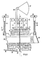
- FIG. 1 shows further details, partly in section, on an even larger scale, as well as assigned representations of the true size dimensions.
- the torch designated as a whole by 1, is suitable for attachment to any commercially available TIG device, in particular for mechanized welding with so-called orbital heads.
- the burner 1 is constructed largely symmetrically to the dash-dotted axis 2, which runs through a rod-shaped tungsten electrode 3.
- the electrode 3 has from its tip 4 to its attachment in a terminal block 5 a length of z. B. 85 mm and a diameter of 4 mm.
- the electrode 3 is in a good heat-conducting connection with two heat sinks 7 and 8 which are arranged on opposite sides of the electrode 3.
- the heat sinks 7 and 8 are 4 mm thick copper strips and each contain two milled coolant channels 9 and 10, which run in a U-shape as leads 11 and 12 to the electrode tip 4 and as leads 13 and 14 from the electrode tip 4 to the terminal block 5, as arrows 15, 16 show. Water is used as the coolant.
- two shielding gas supply lines 17 and 18 are provided on the side facing away from the electrode 3. They run parallel to the electrode 3 up to the area of an insulating cap 20 which is placed over the free ends of the heat sinks 7 and 8.
- the ends of the protective gas supply lines 17 and 18 facing the electrode tip 4 and thus the seam each have an angled area 22 and 23 which runs parallel to the seam base. This area is designed as a nozzle body and is provided with outlet openings for the protective gas.
- the nozzle bodies 22, 23 are advantageously interchangeable.
- two further flat coolant lines 24 and 25 are connected, which can also be designed as copper strips with milled grooves and a cover plate. They are located between the electrode 3 and the protective gas supply lines 17, 18, so that thermal shielding is effected.
- the flat coolant lines 24, 25 are connected to the live heat sinks 7 and 8 via insulating plug connections.
- the space created in this way is used to hold a viewing device 26 which, in the form of an endoscope, a glass fiber optic or the like, enables the weld seam to be observed in the vicinity of the electrode tip 4.
- a focusing screen 27 can be connected to the viewing device.
- a protective gas bell 28 extends over the burner 1 with the electrode 3 and its heat sinks 7 and 8 as well as the protective gas supply lines 17, 18 and has an area 29 made of crystal-clear mineral material as a viewing window on the right-hand side in FIG. 1.
- the protective gas bell serves, among other things, as a thermal shield and as radiation shielding and is provided with water cooling (not shown). This also reduces the temperature of the protective gas.
- the bell 28 should sit as close as possible to the workpiece to be welded. For this purpose, it can be fastened on two screws 30 and 31, which are seated in a frame 32, against the action of springs 33 and 34, which press the bell 28 in the direction of the electrode tip 4.
- a guide tube 36 is fastened with a holding rod 37, which is seated in a bearing body 38.
- the guide tube 36 serves to feed additional material 40, which is guided as a welding wire into the area of the electrode tip 4.
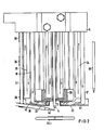
- Fig. 2 clearly shows with its larger scale that the angled areas 22 and 23 as nozzles have finely distributed outlet openings and flow guides 42 so that the flow of the protective gas is as laminar as possible.
- the true dimensions of the burner 1 are shown in FIG. 2 at 44 as the burner cross section and at 45 as a side view.
- the metallic parts of the burner 1 are electrically insulated.
- a heat-resistant lacquer application, which can contain mica, and the insulating cap 20 are used for this purpose. This makes it possible to ignite the arc to the electrode tip 4 by touch and / or by high frequency.
- the electrode tip 4 is shown rotationally symmetrical in the exemplary embodiment. However, it can also be angled to adapt to larger welding gap widths and, for example, can be moved back and forth across the welding gap width during welding with the aid of a preferably adjustable eccentric. This is particularly advantageous when filling deep welding gaps, the upper layers of which, even with a slight inclination of the gap wall, must be considerably wider than the layers at the root of the welding gap.
Priority Applications (1)
| Application Number | Priority Date | Filing Date | Title |
|---|---|---|---|
| AT85103517T ATE40861T1 (de) | 1984-04-06 | 1985-03-25 | Brenner zum wig-schweissen. |
Applications Claiming Priority (2)
| Application Number | Priority Date | Filing Date | Title |
|---|---|---|---|
| DE3413102 | 1984-04-06 | ||
| DE19843413102 DE3413102A1 (de) | 1984-04-06 | 1984-04-06 | Brenner zum wig-schweissen |
Publications (2)
| Publication Number | Publication Date |
|---|---|
| EP0160820A1 EP0160820A1 (de) | 1985-11-13 |
| EP0160820B1 true EP0160820B1 (de) | 1989-02-22 |
Family
ID=6232922
Family Applications (1)
| Application Number | Title | Priority Date | Filing Date |
|---|---|---|---|
| EP85103517A Expired EP0160820B1 (de) | 1984-04-06 | 1985-03-25 | Brenner zum WIG-Schweissen |
Country Status (7)
| Country | Link |
|---|---|
| US (1) | US4617444A (es) |
| EP (1) | EP0160820B1 (es) |
| JP (1) | JPS60227977A (es) |
| AT (1) | ATE40861T1 (es) |
| BR (1) | BR8501556A (es) |
| DE (2) | DE3413102A1 (es) |
| ES (1) | ES295905Y (es) |
Families Citing this family (11)
| Publication number | Priority date | Publication date | Assignee | Title |
|---|---|---|---|---|
| US5373139A (en) * | 1993-02-25 | 1994-12-13 | Westinghouse Electric Corporation | Apparatus and method for narrow groove welding |
| US5756966A (en) * | 1995-09-22 | 1998-05-26 | General Electric Company | Method for joining metal components with improved arc voltage sensing and control |
| US5793009A (en) * | 1996-06-20 | 1998-08-11 | General Electric Company | Apparatus for joining metal components using broad, thin filler nozzle |
| US5958261A (en) * | 1997-07-17 | 1999-09-28 | General Electric Company | Apparatus for welding with preheated filler material |
| US6271495B1 (en) * | 2000-02-04 | 2001-08-07 | The United States Of America As Represented By The Department Of Energy | Narrow groove welding gas diffuser assembly and welding torch |
| DE10214376C1 (de) * | 2002-03-30 | 2003-10-30 | Daimler Chrysler Ag | Schweißbrenner |
| CH700542A1 (de) * | 2009-03-03 | 2010-09-15 | Alstom Technology Ltd | Verfahren zum verbinden zweier, insbesondere rotationssymmetrischer, metallteile, mittels eines wolframinert-gas(wig)-schweissverfahrens sowie vorrichtung zur durchführung des verfahrens. |
| US9352416B2 (en) * | 2009-11-03 | 2016-05-31 | The Secretary, Department Of Atomic Energy, Govt. Of India | Niobium based superconducting radio frequency(SCRF) cavities comprising niobium components joined by laser welding, method and apparatus for manufacturing such cavities |
| US20110132877A1 (en) * | 2009-12-09 | 2011-06-09 | Lincoln Global, Inc. | Integrated shielding gas and magnetic field device for deep groove welding |
| FI20106295A (fi) * | 2010-12-07 | 2012-06-08 | Aalto Korkeakoulusaeaetioe | Kapearailo- MIG/MAG -hitsauspoltin |
| KR101542750B1 (ko) * | 2014-07-21 | 2015-08-10 | 주식회사 우석에스티에스 | 스텐레스 소구경 관 제조방법 |
Family Cites Families (10)
| Publication number | Priority date | Publication date | Assignee | Title |
|---|---|---|---|---|
| US3076085A (en) * | 1960-04-11 | 1963-01-29 | Union Carbide Corp | High current non-consumable hollow electrode |
| CH462982A (fr) * | 1967-09-27 | 1968-09-30 | Secheron Atel | Torche pour le travail à l'arc électrique |
| JPS5581086A (en) * | 1978-12-16 | 1980-06-18 | Kawasaki Heavy Ind Ltd | Tig welding equipment |
| AR230385A1 (es) * | 1979-09-20 | 1984-04-30 | Westinghouse Electric Corp | Soplete de soldadura por arco con electrodo de tungsteno en atmosfera gaseosa,y metodo para soldar una union con abertura profunda y estrecha,utilizando dicho soplete |
| US4309590A (en) * | 1980-02-29 | 1982-01-05 | Westinghouse Electric Corp. | Narrow groove welding torch |
| US4346279A (en) * | 1980-04-24 | 1982-08-24 | Westinghouse Electric Corp. | Narrow gap welding torch with replacement tip |
| DE3032602A1 (de) * | 1980-08-29 | 1982-04-08 | Olaf Reeh GmbH & Co Apparatebau und Schweißtechnik, 8034 Germering | Verstellbaugruppe des drehbaren brennerkopfes einer elektrischen schweisspistole |
| JPS58181472A (ja) * | 1982-04-16 | 1983-10-24 | Nippon Kokan Kk <Nkk> | 狭開先tig溶接方法 |
| DE3220242A1 (de) * | 1982-05-28 | 1983-12-01 | Siemens AG, 1000 Berlin und 8000 München | Engspaltschweisskopf |
| US4532406A (en) * | 1984-02-10 | 1985-07-30 | General Electric Company | Arc welding torch having integrated wire feed |
-
1984
- 1984-04-06 DE DE19843413102 patent/DE3413102A1/de not_active Withdrawn
-
1985
- 1985-03-25 AT AT85103517T patent/ATE40861T1/de not_active IP Right Cessation
- 1985-03-25 EP EP85103517A patent/EP0160820B1/de not_active Expired
- 1985-03-25 DE DE8585103517T patent/DE3568309D1/de not_active Expired
- 1985-04-01 US US06/718,066 patent/US4617444A/en not_active Expired - Fee Related
- 1985-04-03 BR BR8501556A patent/BR8501556A/pt not_active IP Right Cessation
- 1985-04-03 ES ES1985295905U patent/ES295905Y/es not_active Expired
- 1985-04-04 JP JP60071874A patent/JPS60227977A/ja active Pending
Also Published As
| Publication number | Publication date |
|---|---|
| ES295905U (es) | 1987-06-16 |
| ATE40861T1 (de) | 1989-03-15 |
| DE3568309D1 (en) | 1989-03-30 |
| US4617444A (en) | 1986-10-14 |
| DE3413102A1 (de) | 1985-10-17 |
| JPS60227977A (ja) | 1985-11-13 |
| EP0160820A1 (de) | 1985-11-13 |
| BR8501556A (pt) | 1985-12-03 |
| ES295905Y (es) | 1987-12-16 |
Similar Documents
| Publication | Publication Date | Title |
|---|---|---|
| DE69732000T2 (de) | Vorrichtung zum Verbinden metallischer Bauteile mit einer breiten dünnen Zusatzdüse | |
| EP0160820B1 (de) | Brenner zum WIG-Schweissen | |
| EP0543830B1 (de) | Vorrichtung und verfahren zum laserschweissen eines rohres | |
| DE3941558A1 (de) | Laser-verbindungsvorrichtung mit lichtleitfaser | |
| DE60220343T2 (de) | Schweissvorrichtung mit einem miniaturisierten Laserstrahl | |
| DE102007031534A1 (de) | Wolfram-Inertgas-Schweißbrenner | |
| US5373139A (en) | Apparatus and method for narrow groove welding | |
| DE3305521A1 (de) | Schweisspistole | |
| DE2928938C2 (es) | ||
| DE3834224C2 (de) | Lichtbogen-Schutzgasschweißbrenner zum Schweißen an schwer zugänglichen Stellen | |
| DE3503881A1 (de) | Strahlabgabesystem fuer einen co(pfeil abwaerts)2(pfeil abwaerts)-laser | |
| DE19627803C1 (de) | Düsenanordnung zum gleichzeitigen Schweißbearbeiten mit einem Laserstrahl und mit einem Lichtbogen | |
| DE102008063614A1 (de) | Laser-Lichtbogen-Hybrid-Schweißkopf | |
| DE3023838A1 (de) | Loet- bzw. schweissvorrichtung fuer laengsprofile | |
| EP3017901A1 (de) | Wig-schweissbrenner mit kreisbogenförmiger führung | |
| EP0543829B1 (de) | Vorrichtung und verfahren zum laserschweissen eines rohres | |
| EP0376015B1 (de) | Schutzgasschweissbrenner zum Lichtbogenschweissen mit abschmelzender Elektrode | |
| EP3765227A1 (de) | Schweissbrenner | |
| EP0168777B1 (de) | Röntgenröhre | |
| DE3930267A1 (de) | Plasmaschweissbrenner | |
| DE3238497A1 (de) | Einrichtung zum orbital-lichtbogenschweissen | |
| DE613484C (de) | Elektrischer Lichtbogenbrenner zum Schmelzen, Schweissen, Schneiden o. dgl. mittels zweier oder mehrerer sich im Raume kreuzender Elektroden | |
| EP1157770A2 (de) | Laserlötkopf | |
| DE102021133009A1 (de) | Düsenadapter für Laserschneidkopf | |
| DE1887392U (de) | Schweisspistole, insbesondere fuer das lichtbogen-schutzgasschweissen. |
Legal Events
| Date | Code | Title | Description |
|---|---|---|---|
| PUAI | Public reference made under article 153(3) epc to a published international application that has entered the european phase |
Free format text: ORIGINAL CODE: 0009012 |
|
| AK | Designated contracting states |
Designated state(s): AT BE CH DE FR GB IT LI NL SE |
|
| 17P | Request for examination filed |
Effective date: 19851218 |
|
| 17Q | First examination report despatched |
Effective date: 19861028 |
|
| D17Q | First examination report despatched (deleted) | ||
| RAP1 | Party data changed (applicant data changed or rights of an application transferred) |
Owner name: SIEMENS AKTIENGESELLSCHAFT BERLIN UND MUENCHEN |
|
| GRAA | (expected) grant |
Free format text: ORIGINAL CODE: 0009210 |
|
| AK | Designated contracting states |
Kind code of ref document: B1 Designated state(s): AT BE CH DE FR GB IT LI NL SE |
|
| REF | Corresponds to: |
Ref document number: 40861 Country of ref document: AT Date of ref document: 19890315 Kind code of ref document: T |
|
| REF | Corresponds to: |
Ref document number: 3568309 Country of ref document: DE Date of ref document: 19890330 |
|
| ET | Fr: translation filed | ||
| ITF | It: translation for a ep patent filed |
Owner name: STUDIO JAUMANN |
|
| GBT | Gb: translation of ep patent filed (gb section 77(6)(a)/1977) | ||
| PLBE | No opposition filed within time limit |
Free format text: ORIGINAL CODE: 0009261 |
|
| STAA | Information on the status of an ep patent application or granted ep patent |
Free format text: STATUS: NO OPPOSITION FILED WITHIN TIME LIMIT |
|
| 26N | No opposition filed | ||
| ITTA | It: last paid annual fee | ||
| EAL | Se: european patent in force in sweden |
Ref document number: 85103517.0 |
|
| PGFP | Annual fee paid to national office [announced via postgrant information from national office to epo] |
Ref country code: BE Payment date: 19960319 Year of fee payment: 12 |
|
| PGFP | Annual fee paid to national office [announced via postgrant information from national office to epo] |
Ref country code: SE Payment date: 19960320 Year of fee payment: 12 |
|
| PGFP | Annual fee paid to national office [announced via postgrant information from national office to epo] |
Ref country code: NL Payment date: 19960328 Year of fee payment: 12 Ref country code: FR Payment date: 19960328 Year of fee payment: 12 |
|
| PGFP | Annual fee paid to national office [announced via postgrant information from national office to epo] |
Ref country code: DE Payment date: 19960520 Year of fee payment: 12 |
|
| PGFP | Annual fee paid to national office [announced via postgrant information from national office to epo] |
Ref country code: CH Payment date: 19960624 Year of fee payment: 12 |
|
| PGFP | Annual fee paid to national office [announced via postgrant information from national office to epo] |
Ref country code: GB Payment date: 19970224 Year of fee payment: 13 |
|
| PGFP | Annual fee paid to national office [announced via postgrant information from national office to epo] |
Ref country code: AT Payment date: 19970305 Year of fee payment: 13 |
|
| PG25 | Lapsed in a contracting state [announced via postgrant information from national office to epo] |
Ref country code: SE Effective date: 19970326 |
|
| PG25 | Lapsed in a contracting state [announced via postgrant information from national office to epo] |
Ref country code: LI Effective date: 19970331 Ref country code: CH Effective date: 19970331 Ref country code: BE Effective date: 19970331 |
|
| BERE | Be: lapsed |
Owner name: SIEMENS A.G. BERLIN UND MUNCHEN Effective date: 19970331 |
|
| PG25 | Lapsed in a contracting state [announced via postgrant information from national office to epo] |
Ref country code: NL Effective date: 19971001 |
|
| REG | Reference to a national code |
Ref country code: CH Ref legal event code: PL |
|
| PG25 | Lapsed in a contracting state [announced via postgrant information from national office to epo] |
Ref country code: FR Free format text: LAPSE BECAUSE OF NON-PAYMENT OF DUE FEES Effective date: 19971128 |
|
| NLV4 | Nl: lapsed or anulled due to non-payment of the annual fee |
Effective date: 19971001 |
|
| PG25 | Lapsed in a contracting state [announced via postgrant information from national office to epo] |
Ref country code: DE Effective date: 19971202 |
|
| EUG | Se: european patent has lapsed |
Ref document number: 85103517.0 |
|
| REG | Reference to a national code |
Ref country code: FR Ref legal event code: ST |
|
| PG25 | Lapsed in a contracting state [announced via postgrant information from national office to epo] |
Ref country code: GB Free format text: LAPSE BECAUSE OF NON-PAYMENT OF DUE FEES Effective date: 19980325 Ref country code: AT Free format text: LAPSE BECAUSE OF NON-PAYMENT OF DUE FEES Effective date: 19980325 |
|
| GBPC | Gb: european patent ceased through non-payment of renewal fee |
Effective date: 19980325 |