EP0160163B1 - Steuersystem für eine frequenzvariable Stromversorgung - Google Patents
Steuersystem für eine frequenzvariable Stromversorgung Download PDFInfo
- Publication number
- EP0160163B1 EP0160163B1 EP19850101044 EP85101044A EP0160163B1 EP 0160163 B1 EP0160163 B1 EP 0160163B1 EP 19850101044 EP19850101044 EP 19850101044 EP 85101044 A EP85101044 A EP 85101044A EP 0160163 B1 EP0160163 B1 EP 0160163B1
- Authority
- EP
- European Patent Office
- Prior art keywords
- power source
- control signal
- frequency
- motor
- output
- Prior art date
- Legal status (The legal status is an assumption and is not a legal conclusion. Google has not performed a legal analysis and makes no representation as to the accuracy of the status listed.)
- Expired
Links
Images


Classifications
-
- H—ELECTRICITY
- H02—GENERATION; CONVERSION OR DISTRIBUTION OF ELECTRIC POWER
- H02J—CIRCUIT ARRANGEMENTS OR SYSTEMS FOR SUPPLYING OR DISTRIBUTING ELECTRIC POWER; SYSTEMS FOR STORING ELECTRIC ENERGY
- H02J9/00—Circuit arrangements for emergency or stand-by power supply, e.g. for emergency lighting
- H02J9/04—Circuit arrangements for emergency or stand-by power supply, e.g. for emergency lighting in which the distribution system is disconnected from the normal source and connected to a standby source
- H02J9/06—Circuit arrangements for emergency or stand-by power supply, e.g. for emergency lighting in which the distribution system is disconnected from the normal source and connected to a standby source with automatic change-over, e.g. UPS systems
- H02J9/062—Circuit arrangements for emergency or stand-by power supply, e.g. for emergency lighting in which the distribution system is disconnected from the normal source and connected to a standby source with automatic change-over, e.g. UPS systems for AC powered loads
Definitions
- the invention relates to in an airflow control apparatus having a ventilator-actuating motor driven at a rotational speed corresponding to a power supply frequency, a VF (variable frequency) power source connected to said motor, a controller for feeding a control signal to said VF power source so as to determine the output frequency thereof, and an abnormal signal detector including means for detecting an abnormality relative to the control signal fed to said VF power source and producing an output.
- the invention particularly refers to a control apparatus in which the control signals cannot be sent to the VF power source due to accidental disconnection or short-circuit in the signal line.
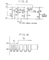
- FIG. 1 A conventional VF power source operating system of this kind is shown in Fig. 1, in which 1 is a commercial power line, 2 is a switch, 3 is a VF power source for controlling the speed of a motor 4, 6 is the rotary component of a fan, a pump or the like, 5 is a mechanical coupler for coupling the motor 4 and the rotary component 6, 7 is a controller which gives a frequency control signal to the VF power source 3, 8 is a control command given to the controller 7 and 9 is a signal line interconnecting the controller 7 and the VF power source 3.
- 1 is a commercial power line
- 2 is a switch
- 3 a VF power source for controlling the speed of a motor 4
- 6 is the rotary component of a fan, a pump or the like
- 5 is a mechanical coupler for coupling the motor 4 and the rotary component
- 7 is a controller which gives a frequency control signal to the VF power source 3
- 8 is a control command given to the controller 7
- 9 is a
- t 1 and t 3 are a time points when an increase control command is given and when a decrease control command is given, respectively
- t 2 and t 4 are time points when the output of the VF power source completed to increase and decrease, respectively
- t 5 is a time point when an accident occurred in the signal line 9 and t 6 is a time point when the output of the VF power source 3 has completed its change after an accident has occurred.
- the rotary component 6 is regarded as a fan for supplying its output (air) to the boiler, not shown, of a power plant.
- the VF power source 3 receives power through the switch 2 from commercial power line 1 and provides an output for driving the motor 4.
- the revolving rate n of the motor 4 is represented by the following expression: where F is the frequency of the output power of the power source and P is the number of poles of the motor.
- the revolving rate n is proportional to the frequency F of the output power of the power source, that is, the revolving rate n of the motor 4 varies according to the variation of the output frequency F of the VF power source 3.
- the motor 4 is coupled with the fan 6 with a coupler 5 and the fan 6 supplies air to the boiler at an output air supply rate Q which is approximately proportional to the revolving rate n of the motor 4.
- the air demand of the boiler changes as the power demand of the associated power grid changes or the fuel supply mode of the boiler changes.
- a control command 8 to change the air supply rate is given to the controller 7 and a control signal for deciding the air supply rate Q is given through the signal line 9 to the VF power source 3, and then the VF power source 3 provides an output of a frequency F corresponding to the required air supply rate Q.
- Fig. 2 is a time chart for explaining the normal actions of the conventional VF power source system shown in Fig. 1.
- the control command 8 requests the increase of the air supply rate Q at a time point t 1 and the decrease of the increased air supply rate to the original air supply rate at a time point t 3 , the output of the controller 7 is given through the signal line 9 to the VF power source 3.
- the VF power source 3 is designed to respond to the request for the change of the output at a fixed increase rate or a fixed decrease rate, therefore the change of the output frequency F of the VF power source 3 is delayed slightly from the time ponts t 1 and t 3 of request for the change, and the output frequency changing action of the VF power source 3 is completed at the time points t 2 and t 4 . That is, if it is desired to change the output air supply rate Q of the fan 6, the revolving rate n of the motor 4 is changed by changing the output frequency F of the VF power source 3.
- Fig. 3 is a time chart showing the changes of controlled factors in case of a disconnection of the signal line 9 as, for example, by loosening or the falling off of the connecting terminals.
- the control command 8 is requesting a fixed air supply rate Q.
- the input signal of the VF power source 3 becomes zero. Consequently, as explained in connection with Fig. 2, the output frequency F of the VF power source decreases with a slight delay to a lower limit value causing the decrease of the revolving rate n of the motor 4, and thereby the output air supply rate Q is decreased.
- the output frequency of the VF power source 3 varies unnecessarily in case an accident occurs in the control signal to be given to the VF power source 3, which entails unstable operation of the motor 4 and the rotary component 6 and the resulting accident in the system.
- variable frequency power source operating system capable of operating the associated variable frequency power source so that the sudden and great change of the revolving rate of the motor driven by the output of the variable frequency power source is obviated in case an abnormality occurred in the control signal for deciding the output frequency of the variable frequency power source.
- an inverter circuit which is tuned to the frequency of the commercial power supply. If a failure detector detects that the inverter is out of operation, then the supply is connected to the commercial power supply to continue the supply to the load.
- an airflow control apparatus is characterized by a control signal generator provided in said controller for generating said contrbl signal in the form of a pulse signal of predetermined fixed pulse magnitude and of a pulse width or a frequency corresponding to the output frequency of said VF power source; and said abnormal signal detector comprising means for detecting the pulse magnitude of said control signal to decide that the control signal is abnormal when the detected pulse magnitude does not lie within a predetermined range including the fixed pulse magnitude.
- a control signal generator provided in said controller for generating said contrbl signal in the form of a pulse signal of predetermined fixed pulse magnitude and of a pulse width or a frequency corresponding to the output frequency of said VF power source
- said abnormal signal detector comprising means for detecting the pulse magnitude of said control signal to decide that the control signal is abnormal when the detected pulse magnitude does not lie within a predetermined range including the fixed pulse magnitude.
- VF power source operating systems according to the present invention will be described hereinafter in connection with the accompanying drawings.
- the components indicated at reference characters 1 to 11 are substantially the same as those shown in Fig. 1, except that the controller 7 has a control signal generator 7B and the VF power source 3 has an abnormal signal detector 3B.
- Fig. 5 shows the circuit of the control signal generator 7B, which will be described in detail afterward.
- the control signal generator 7B generates a control signal in the form of a pulse trains of a pulse width W1 or a pulse width W2 when the level of the control signal 8 is F1 or F2 respectively and supplies the control signal to the abnormal signal detector 3B.
- T 1' T 2 , T 3 and T 4 are transistors
- R 1 to R 7 are resistances
- at C 1 and C 2 are capacitors
- ZD is a Zener diode
- at +Es is the voltage of a DC power source
- at VC 1 is the terminal voltage of the capacitor C 1 .
- the VF power source operating system is applied advantageously for controlling the air supply rate of the blower unit of a boiler as shown in Fig. 7, for instance.
- the rotary component 6 consistdof a shaft 6a coupled with a motor 4 with a mechanical coupler 5 and a fan 6b attached to the shaft 6a.
- the fan 6b is disposed within an air duct 12 to generate an air current in a direction indicated by the arrow 13.
- An air flow rate regulating mechanism 14 provided as a subsidiary means to regulate the flow rate of the air in the air duct 12 includes a plurality of vanes 14a disposed within the air duct and a driving device 14b which regulates the vane angle according to an input control signal 15. Indicated at 12a and 12b are the inlet and the outlet of the air duct respectively.
- Fig. 6 the relation between the pulse width W, of the pulse wave and the magnitude F, of the control signal 8 is represented by where K is a constant and i is an arbitrary positive integer.
- the control signal generator for generating pulse signals of pulse widths W 1 and W 2 is included in the controller 7 shown in Fig. 7.
- the frequency of an output power of the VF power source 3 for driving the motor 4 is dependent only on the pulse width W, of the pulse signal as defined by Expression (2).
- voltagVc1 C1R1 when the transistor T 1 changes from ON state into OFF state and after the voltage V c1 has exceeded an input voltage E, the transistor T 2 , hence the transistor T 3 also change from OFF state into ON state.
- the transistor T 3 When the transistor T 3 is in ON state, the base current of the transistor T flows through the Zener diode ZD, then the transistors T 2 and T 3 remain in OFF state.
- the capacitor C 2 is provided to secure a time period necessary to make the voltage V c1 drop to zero volt by discharging the capacitor C 1 through the transistor T 1 .
- the input voltage varies, as shown in Fig. 8, between a level E, 1 (a low value) and a level E, 2 (a high value)
- the time for the voltage V c1 to reach the input voltage E is proportional to E,. Therefore, the output signal E o having pulses of pulse widths proportional to the input voltage E, and of input-frequency relation as shown in Fig. 8 is produced.
- the pulse magnitude H of the pulse signal being transmitted through the signal line 9 decreases to a reduced magnitude (one of reduced magnitudes including zero) at the input of the VF power source 3 even if any particular change does not occur in the control signal 8. Accordingly, the abnormal signal detector 3B for detecting the deviation of the pulse magnitude H of the pulse signal being supplied through the signal line 9 from the normal magnitude is provided to decide if the signal line 9 is in an abnormal condition, such as disconnection, and to prevent the change of the output signal of the VF power source 3 so that the existing operating condition of the motor is maintained.
- the present invention is applicable for the same effects also to controlling a rotary component other than a fan, such as a pump, or as a VF power source operating system of a system other than a power plant.
- the abnormal condition is not limited thereto and may be an accident such as short-circuit other than disconnection of the line 9.
- the minimum pulse magnitude and the maximum pulse magnitude of the pulse signal are zero and H respectively by way of example, however, the reference pulse magnitude is not necessarily be limited to zero.
- the frequency control input applied to the VF power source 3 is a pulse signal of variable pulse width, however, a numerical signal produced through digital coding may be used instead of the pulse signal.
- Figure 9 shows another embodiment of the present invention.
- This embodiment is different from the embodiment shown in Fig. 4 in respect of the insertion of a switch 10 between a VF power source 3 and a motor 4 and the provision of an AC power supply line having a switch 11 for connecting the motor 4 to a commercial power supply.
- This embodiment changes over the power source of the motor 4 from the VF power source 3 to the commercial power supply when the abnormal signal detector 3B detects an abnormality in the control signal.
- This power source changeover action is performed preferably in cooperation with an air supply rate control mechanism 14 shown in Fig. 7.
- the abnormal signal detector 3B cancels the fixation of the vanes 14a and changes the control mode of the air supply rate control mechanism 14 into an automatic control mode so that the degree of opening of the vanes 14a is regulated through a driving rod 14b according to an input control signal 15.
- the abnormal signal detector 3B raises the output of the VF power source 3 near to the rated value thereof and increases the output frequency F to make the revolving rate of the motor 4 approach the rated revolving rate.
- the output of the VF power source 3 is raised slowly and gradually.
- the switch 2 of Fig. 9 is opened and the switch 11 of Fig. 9 is closed to disconnect the motor 4 from the VF power source 3 and to connect the same to the commercial power supply 1.
- This control procedure performed by this embodiment prevents the sudden change of the frequency of the input power supplied to the motor 4 over a wide range which occurs when the power source of the motor 4 is changed over simply from the VF power source 3 to the commercial power supply 1 immediately after the abnormality in the signal line 9 has been detected, and thereby the variation of the air supply rate in changing the power source is limited within a small extent.
- the power source of the motor 4 is changed over safely from the VF power source 3 to the commercial power supply 1 to continue the operation of the system even if any abnormality occurs in the signal line 9.
- the present invention is applicable for the same effects also to controlling a rotary component other than a fan, such as a pump, or to a VF power source operating system of a system other than a power plant.
- the second embodiment of the present invention has been described in terms of functions in case of the disconnection of the signal line 9 by way of example, however, the abnormal condition is not limited thereto and may be an accid- cent such as short-circuit.
- the minimum pulse magnitude and the maximum pulse magnitude of the pulse signal are zero and H respectively by way of example, however, the reference pulse magnitude is not necessarily be limited to zero.
- the power source of the motor is changed over from the VF power source 3 to the commercial power supply 1 after the output frequency of the VF power source has been raised near to the rated output frequency thereof, however, it is obvious that the process of changing the power source of the motor is not limited thereto and may be an other process in which the power source is changed over immediately after the detection of an abnormal signal by the abnormal signal detector.
- the frequency control- input applied to the VF power source 3 is a pulse signal of variable pulse width, however, a numerical signal produced through digital coding may be used instead of the pulse signal.
Landscapes
- Business, Economics & Management (AREA)
- Emergency Management (AREA)
- Engineering & Computer Science (AREA)
- Power Engineering (AREA)
- Control Of Ac Motors In General (AREA)
- Control Of Electric Motors In General (AREA)
- Control Of Positive-Displacement Air Blowers (AREA)
Claims (4)
Applications Claiming Priority (4)
| Application Number | Priority Date | Filing Date | Title |
|---|---|---|---|
| JP65425/84 | 1984-04-02 | ||
| JP65424/84 | 1984-04-02 | ||
| JP59065424A JPS60210195A (ja) | 1984-04-02 | 1984-04-02 | 可変周波数電源運転方式 |
| JP59065425A JPS60210196A (ja) | 1984-04-02 | 1984-04-02 | 可変周波数電源運転方式 |
Publications (2)
| Publication Number | Publication Date |
|---|---|
| EP0160163A1 EP0160163A1 (de) | 1985-11-06 |
| EP0160163B1 true EP0160163B1 (de) | 1988-06-08 |
Family
ID=26406571
Family Applications (1)
| Application Number | Title | Priority Date | Filing Date |
|---|---|---|---|
| EP19850101044 Expired EP0160163B1 (de) | 1984-04-02 | 1985-02-01 | Steuersystem für eine frequenzvariable Stromversorgung |
Country Status (4)
| Country | Link |
|---|---|
| US (1) | US4651072A (de) |
| EP (1) | EP0160163B1 (de) |
| CA (1) | CA1261390A (de) |
| DE (1) | DE3563288D1 (de) |
Families Citing this family (7)
| Publication number | Priority date | Publication date | Assignee | Title |
|---|---|---|---|---|
| JPH0610830B2 (ja) * | 1988-04-09 | 1994-02-09 | シャープ株式会社 | Icカードのクロック信号切換装置 |
| JPH0729749B2 (ja) * | 1989-07-21 | 1995-04-05 | 株式会社日立製作所 | 乗客コンベアの制御装置 |
| US5436827A (en) * | 1994-06-30 | 1995-07-25 | Tandem Computers Incorporated | Control interface for customer replaceable fan unit |
| US8178145B1 (en) | 2007-11-14 | 2012-05-15 | JMC Enterprises, Inc. | Methods and systems for applying sprout inhibitors and/or other substances to harvested potatoes and/or other vegetables in storage facilities |
| US9605890B2 (en) | 2010-06-30 | 2017-03-28 | Jmc Ventilation/Refrigeration, Llc | Reverse cycle defrost method and apparatus |
| US8991123B2 (en) | 2013-03-15 | 2015-03-31 | Storage Systems Northwest, Inc. | Environmentally controlled storage facility for potatoes and other crops |
| US10076129B1 (en) | 2016-07-15 | 2018-09-18 | JMC Enterprises, Inc. | Systems and methods for inhibiting spoilage of stored crops |
Family Cites Families (8)
| Publication number | Priority date | Publication date | Assignee | Title |
|---|---|---|---|---|
| DE1252303B (de) * | 1963-04-23 | 1967-10-19 | The English Electric Company Limited, London | Elektrischer Regler |
| AT302456B (de) * | 1968-05-17 | 1972-10-10 | Elin Union Ag | Einrichtung zum Schutz gegen Stillstands-Überlastung drehzahlgeregelter Gleichstrommomotoren oder anderer Kollektormaschinen |
| US3777122A (en) * | 1971-07-30 | 1973-12-04 | Shell Oil Co | Process and apparatus for the automatic control of a variable |
| US3793573A (en) * | 1972-09-28 | 1974-02-19 | Hitachi Ltd | Thyristor motor |
| US3821630A (en) * | 1973-08-02 | 1974-06-28 | Gen Electric | Commutation failure detection and control for scr inverters |
| CA1005896A (en) * | 1974-10-02 | 1977-02-22 | Alfred M. Hase | Electrical load transfer control system |
| US4281276A (en) * | 1979-04-24 | 1981-07-28 | General Electric Company | Dual mode AC motor drive system |
| KR890002532B1 (ko) * | 1983-11-16 | 1989-07-13 | 미쓰비시전기 주식회사 | 풍량 제어장치 |
-
1985
- 1985-02-01 EP EP19850101044 patent/EP0160163B1/de not_active Expired
- 1985-02-01 DE DE8585101044T patent/DE3563288D1/de not_active Expired
- 1985-02-06 US US06/698,849 patent/US4651072A/en not_active Expired - Fee Related
- 1985-02-27 CA CA000475326A patent/CA1261390A/en not_active Expired
Also Published As
| Publication number | Publication date |
|---|---|
| DE3563288D1 (en) | 1988-07-14 |
| EP0160163A1 (de) | 1985-11-06 |
| US4651072A (en) | 1987-03-17 |
| CA1261390A (en) | 1989-09-26 |
Similar Documents
| Publication | Publication Date | Title |
|---|---|---|
| US5953902A (en) | Control system for controlling the rotational speed of a turbine, and method for controlling the rotational speed of a turbine during load shedding | |
| US4266177A (en) | Power factor control system for AC induction motors | |
| EP0572588B1 (de) | Vorrichtung zur regelung eines generators | |
| DE60128298T2 (de) | Maschinenbetriebener Generator | |
| US4843297A (en) | Microprocessor speed controller | |
| US6469276B1 (en) | Control of weld and auxiliary power output of a generator type welding power supply | |
| EP0160163B1 (de) | Steuersystem für eine frequenzvariable Stromversorgung | |
| US4292534A (en) | Power and speed control device for a turbo-generator set | |
| JP2001524299A (ja) | ファン冷却装置 | |
| EP0142679B1 (de) | Luftstromsteuervorrichtung | |
| US5461296A (en) | Bumpless rotating start | |
| US5594312A (en) | Apparatus having an automatic firing arrangement | |
| JPS6062606A (ja) | 蒸気タ−ビン圧力変化率制限方法および装置 | |
| US4682095A (en) | Circuit arrangement for controlling starting current of a motor | |
| US4112342A (en) | Solid state controller | |
| GB2160733A (en) | Monostable relay control | |
| KR900003799B1 (ko) | 제어 시스템 | |
| EP0160787B1 (de) | Regelsystem für eine frequenzvariable Stromversorgung | |
| JPH0749118A (ja) | 自動燃焼制御装置を備えた装置 | |
| JPS5956827A (ja) | 自家発電装置 | |
| EP0045846A1 (de) | Automatisches Geschwindigkeitsregelsystem | |
| EP0248380A2 (de) | Steuerungsvorrichtung einer Einheit mit veränderbarer Luftmenge | |
| KR890003935B1 (ko) | 가변주파수 전원운전방식 | |
| KR950014758B1 (ko) | 유도전동기의 제어회로 및 제어방법 | |
| JPH04248400A (ja) | 発電機の自動電圧制御装置 |
Legal Events
| Date | Code | Title | Description |
|---|---|---|---|
| PUAI | Public reference made under article 153(3) epc to a published international application that has entered the european phase |
Free format text: ORIGINAL CODE: 0009012 |
|
| AK | Designated contracting states |
Designated state(s): CH DE GB LI |
|
| 17P | Request for examination filed |
Effective date: 19860115 |
|
| 17Q | First examination report despatched |
Effective date: 19861022 |
|
| D17Q | First examination report despatched (deleted) | ||
| GRAA | (expected) grant |
Free format text: ORIGINAL CODE: 0009210 |
|
| AK | Designated contracting states |
Kind code of ref document: B1 Designated state(s): CH DE GB LI |
|
| REF | Corresponds to: |
Ref document number: 3563288 Country of ref document: DE Date of ref document: 19880714 |
|
| PLBE | No opposition filed within time limit |
Free format text: ORIGINAL CODE: 0009261 |
|
| STAA | Information on the status of an ep patent application or granted ep patent |
Free format text: STATUS: NO OPPOSITION FILED WITHIN TIME LIMIT |
|
| 26N | No opposition filed | ||
| PGFP | Annual fee paid to national office [announced via postgrant information from national office to epo] |
Ref country code: GB Payment date: 19940124 Year of fee payment: 10 |
|
| PGFP | Annual fee paid to national office [announced via postgrant information from national office to epo] |
Ref country code: DE Payment date: 19940209 Year of fee payment: 10 |
|
| PGFP | Annual fee paid to national office [announced via postgrant information from national office to epo] |
Ref country code: CH Payment date: 19940215 Year of fee payment: 10 |
|
| PG25 | Lapsed in a contracting state [announced via postgrant information from national office to epo] |
Ref country code: GB Effective date: 19950201 |
|
| PG25 | Lapsed in a contracting state [announced via postgrant information from national office to epo] |
Ref country code: LI Effective date: 19950228 Ref country code: CH Effective date: 19950228 |
|
| GBPC | Gb: european patent ceased through non-payment of renewal fee |
Effective date: 19950201 |
|
| PG25 | Lapsed in a contracting state [announced via postgrant information from national office to epo] |
Ref country code: DE Effective date: 19951101 |