EP0159552B1 - Store à rouleau avec toile et bras articulé - Google Patents
Store à rouleau avec toile et bras articulé Download PDFInfo
- Publication number
- EP0159552B1 EP0159552B1 EP85103480A EP85103480A EP0159552B1 EP 0159552 B1 EP0159552 B1 EP 0159552B1 EP 85103480 A EP85103480 A EP 85103480A EP 85103480 A EP85103480 A EP 85103480A EP 0159552 B1 EP0159552 B1 EP 0159552B1
- Authority
- EP
- European Patent Office
- Prior art keywords
- stop
- threaded bolt
- guide
- bearing
- shaft
- Prior art date
- Legal status (The legal status is an assumption and is not a legal conclusion. Google has not performed a legal analysis and makes no representation as to the accuracy of the status listed.)
- Expired
Links
Images


Classifications
-
- E—FIXED CONSTRUCTIONS
- E04—BUILDING
- E04F—FINISHING WORK ON BUILDINGS, e.g. STAIRS, FLOORS
- E04F10/00—Sunshades, e.g. Florentine blinds or jalousies; Outside screens; Awnings or baldachins
- E04F10/02—Sunshades, e.g. Florentine blinds or jalousies; Outside screens; Awnings or baldachins of flexible canopy materials, e.g. canvas ; Baldachins
- E04F10/06—Sunshades, e.g. Florentine blinds or jalousies; Outside screens; Awnings or baldachins of flexible canopy materials, e.g. canvas ; Baldachins comprising a roller-blind with means for holding the end away from a building
- E04F10/0644—Sunshades, e.g. Florentine blinds or jalousies; Outside screens; Awnings or baldachins of flexible canopy materials, e.g. canvas ; Baldachins comprising a roller-blind with means for holding the end away from a building with mechanisms for unrolling or balancing the blind
- E04F10/0648—Sunshades, e.g. Florentine blinds or jalousies; Outside screens; Awnings or baldachins of flexible canopy materials, e.g. canvas ; Baldachins comprising a roller-blind with means for holding the end away from a building with mechanisms for unrolling or balancing the blind acting on the roller tube
-
- E—FIXED CONSTRUCTIONS
- E04—BUILDING
- E04F—FINISHING WORK ON BUILDINGS, e.g. STAIRS, FLOORS
- E04F10/00—Sunshades, e.g. Florentine blinds or jalousies; Outside screens; Awnings or baldachins
- E04F10/02—Sunshades, e.g. Florentine blinds or jalousies; Outside screens; Awnings or baldachins of flexible canopy materials, e.g. canvas ; Baldachins
- E04F10/06—Sunshades, e.g. Florentine blinds or jalousies; Outside screens; Awnings or baldachins of flexible canopy materials, e.g. canvas ; Baldachins comprising a roller-blind with means for holding the end away from a building
- E04F10/0611—Sunshades, e.g. Florentine blinds or jalousies; Outside screens; Awnings or baldachins of flexible canopy materials, e.g. canvas ; Baldachins comprising a roller-blind with means for holding the end away from a building with articulated arms supporting the movable end of the blind for deployment of the blind
- E04F10/0618—Sunshades, e.g. Florentine blinds or jalousies; Outside screens; Awnings or baldachins of flexible canopy materials, e.g. canvas ; Baldachins comprising a roller-blind with means for holding the end away from a building with articulated arms supporting the movable end of the blind for deployment of the blind whereby the pivot axis of the articulation is perpendicular to the roller
-
- E—FIXED CONSTRUCTIONS
- E04—BUILDING
- E04F—FINISHING WORK ON BUILDINGS, e.g. STAIRS, FLOORS
- E04F10/00—Sunshades, e.g. Florentine blinds or jalousies; Outside screens; Awnings or baldachins
- E04F10/02—Sunshades, e.g. Florentine blinds or jalousies; Outside screens; Awnings or baldachins of flexible canopy materials, e.g. canvas ; Baldachins
- E04F10/06—Sunshades, e.g. Florentine blinds or jalousies; Outside screens; Awnings or baldachins of flexible canopy materials, e.g. canvas ; Baldachins comprising a roller-blind with means for holding the end away from a building
- E04F10/0637—Sunshades, e.g. Florentine blinds or jalousies; Outside screens; Awnings or baldachins of flexible canopy materials, e.g. canvas ; Baldachins comprising a roller-blind with means for holding the end away from a building with mechanisms for adjusting the inclination of the blind
- E04F10/064—Sunshades, e.g. Florentine blinds or jalousies; Outside screens; Awnings or baldachins of flexible canopy materials, e.g. canvas ; Baldachins comprising a roller-blind with means for holding the end away from a building with mechanisms for adjusting the inclination of the blind whereby the mechanism changes the inclination of the blind during unrolling
-
- E—FIXED CONSTRUCTIONS
- E04—BUILDING
- E04F—FINISHING WORK ON BUILDINGS, e.g. STAIRS, FLOORS
- E04F10/00—Sunshades, e.g. Florentine blinds or jalousies; Outside screens; Awnings or baldachins
- E04F10/02—Sunshades, e.g. Florentine blinds or jalousies; Outside screens; Awnings or baldachins of flexible canopy materials, e.g. canvas ; Baldachins
- E04F10/06—Sunshades, e.g. Florentine blinds or jalousies; Outside screens; Awnings or baldachins of flexible canopy materials, e.g. canvas ; Baldachins comprising a roller-blind with means for holding the end away from a building
- E04F10/0644—Sunshades, e.g. Florentine blinds or jalousies; Outside screens; Awnings or baldachins of flexible canopy materials, e.g. canvas ; Baldachins comprising a roller-blind with means for holding the end away from a building with mechanisms for unrolling or balancing the blind
- E04F10/0659—Control systems therefor
-
- E—FIXED CONSTRUCTIONS
- E04—BUILDING
- E04F—FINISHING WORK ON BUILDINGS, e.g. STAIRS, FLOORS
- E04F10/00—Sunshades, e.g. Florentine blinds or jalousies; Outside screens; Awnings or baldachins
- E04F10/02—Sunshades, e.g. Florentine blinds or jalousies; Outside screens; Awnings or baldachins of flexible canopy materials, e.g. canvas ; Baldachins
- E04F10/06—Sunshades, e.g. Florentine blinds or jalousies; Outside screens; Awnings or baldachins of flexible canopy materials, e.g. canvas ; Baldachins comprising a roller-blind with means for holding the end away from a building
- E04F10/0666—Accessories
- E04F10/067—Accessories acting as intermediate support of the flexible canopy
-
- E—FIXED CONSTRUCTIONS
- E04—BUILDING
- E04F—FINISHING WORK ON BUILDINGS, e.g. STAIRS, FLOORS
- E04F10/00—Sunshades, e.g. Florentine blinds or jalousies; Outside screens; Awnings or baldachins
- E04F10/02—Sunshades, e.g. Florentine blinds or jalousies; Outside screens; Awnings or baldachins of flexible canopy materials, e.g. canvas ; Baldachins
- E04F10/06—Sunshades, e.g. Florentine blinds or jalousies; Outside screens; Awnings or baldachins of flexible canopy materials, e.g. canvas ; Baldachins comprising a roller-blind with means for holding the end away from a building
- E04F10/0666—Accessories
- E04F10/0674—Accessories acting as separate supporting bar
-
- E—FIXED CONSTRUCTIONS
- E04—BUILDING
- E04F—FINISHING WORK ON BUILDINGS, e.g. STAIRS, FLOORS
- E04F10/00—Sunshades, e.g. Florentine blinds or jalousies; Outside screens; Awnings or baldachins
- E04F10/02—Sunshades, e.g. Florentine blinds or jalousies; Outside screens; Awnings or baldachins of flexible canopy materials, e.g. canvas ; Baldachins
- E04F10/06—Sunshades, e.g. Florentine blinds or jalousies; Outside screens; Awnings or baldachins of flexible canopy materials, e.g. canvas ; Baldachins comprising a roller-blind with means for holding the end away from a building
- E04F10/0685—Covers or housings for the rolled-up blind
- E04F10/0688—Covers or housings for the rolled-up blind with the housing taking up the articulated arms
-
- E—FIXED CONSTRUCTIONS
- E04—BUILDING
- E04F—FINISHING WORK ON BUILDINGS, e.g. STAIRS, FLOORS
- E04F10/00—Sunshades, e.g. Florentine blinds or jalousies; Outside screens; Awnings or baldachins
- E04F10/02—Sunshades, e.g. Florentine blinds or jalousies; Outside screens; Awnings or baldachins of flexible canopy materials, e.g. canvas ; Baldachins
- E04F10/06—Sunshades, e.g. Florentine blinds or jalousies; Outside screens; Awnings or baldachins of flexible canopy materials, e.g. canvas ; Baldachins comprising a roller-blind with means for holding the end away from a building
- E04F10/0692—Front bars
Definitions
- the invention relates to an awning according to the preamble of claim 1.
- Such an awning is known from DE-A-2 853 286 (Loos).
- the locking element is only guided in a guide arranged laterally in the tiltable bearing block from the counter-stop.
- the two gearing arms of the locking element directed towards the stop engage behind the stop on the side facing away from the counter-stop.
- the gusts of wind transmitted from the extended awning fabric via the articulated arms act on the fork arms of the locking element, so that they can bend due to the lateral guidance of the locking element in such a way that when the awning is retracted, the locking member moves back into the unlocking element Position in which the fork arms are also in the guide, is only possible with great effort or is no longer possible.
- the fork arms In order to make the locking element movable again, the fork arms must be straightened again or the locking element must be replaced, which can generally only be carried out by a specialist.
- the push and pull rod connecting the locking member to the articulated arm can be bent and thus become unusable.
- the invention has for its object to design the tilt limiter with a high-impact protection of a generic awning so that its proper functioning can not be impaired even with very large gusts of wind.
- the force applied by gusts of wind at the stop is directly transmitted via the sleeve area on both sides of the longitudinal slots or opposite the angled slots to the guide wall, which is adapted to the outline of the coupling sleeve, which is why sleeve deformation is no longer possible is.
- the stop sleeve with stop pin or this alone has a relatively large pressure area, by means of which impacts are distributed over such a large area that deformations are also avoided thereby.
- the locking member can only be moved over a short distance, or is only rotated about its axis, space is saved parallel to the fabric shaft.
- the relatively large power transmission area also allows for a small dimensioning of the interacting parts, the construction takes up little space and the overall diameter can be kept small.
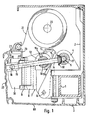
- FIGS. 1 to 3 A first embodiment of an awning designed according to the invention is shown in FIGS. 1 to 3.
- a support tube 1 is attached to a building wall or the like by means of support brackets 2, which carry a housing 3.
- the support tube 1 carries a fabric shaft 20 arranged above it for an awning fabric 21 via a holder (not shown).
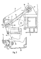
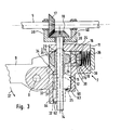
- a tilt bearing 6 is provided for a tiltable bearing block 7, which according to FIG. 3 has a swivel joint 8 for the upper arm 9 of the associated two-armed joint arm.
- Upper and lower arm 9, 10 of each articulated arm are connected to one another via an articulated joint.
- a drop profile 22 is connected via a joint 23, to which the end edge of the cloth 21 is attached.
- the bearing blocks 7 When the fabric 21 is unwound from the fabric shaft 20, the bearing blocks 7 first tilt around their tilting bearing 6 under the influence of their own weight and that of the articulated arms with a drop profile 22 over a fixed tilting angle. The folded articulated arms then begin to stretch, leaving them off Driving movement can be supported in a known manner by springs or the like. Between the upper and lower arm 9, 10 of each articulated arm.
- the tilt angle can be set or adjusted by an adjustable and adjustable tilt limiter assigned to each bearing block 7.
- Each tilt limiter has a tube-like guide 11 at the top of the bearing block 7 with two peripheral slots 12, 13, which are traversed by a threaded bolt 14 which is rotatably arranged at the upper region of the bearing plate 4 with its upper end but is secured against axial displacement.
- a stop sleeve 15 with stop pin 16 is screwed on from its other end.
- This sleeve 15 with internal thread is slidable on the bearing block 7, but non-rotatably.
- the flat end face 24 of the pin 16 slidably abuts a counter surface 25 formed on a cheek-like bracket block 60.
- a projection 31 which is offset outwards with respect to the pin axis can be provided, which remains outside the guide body 11 even when the bearing block 7 is tilted.
- the likewise flat end surface 32 of the projection 31 interacts with a counter surface 33 on the bearing block 7 and an extension 64 on it.
- a stop 63 on the shoulder 60 and / or a stop 62 on the shoulder 64 prevent the stop sleeve 15 from being inadvertently unscrewed from the threaded bolt 14.
- an actuatable adjusting shaft 5 is rotatably mounted on the bearing plate 4, on which a bevel gear 17 is arranged in a rotationally fixed manner, which is in engagement with a bevel gear 18 fixed at the upper end of the threaded bolt 14. If the adjusting shaft 5 is rotated, depending on the direction of rotation, the non-rotatably held stop sleeve 15 is either displaced towards or away from the guide 11 and thereby changes the tilt angle.
- the bearing block 7 tilts its guide 11 slides from the starting position according to FIG. 1 on the shaft of the pivoting threaded bolt 14 until, according to FIG. 2, the stop sleeve 15 and / or its stop pin 16 rests directly or indirectly on the inner wall of the guide body 11 .
- the threaded bolt 14 is mounted on the bearing plate 4 on the web of a swivel bracket 39, the legs of which have bores 40 for reaching through the adjusting shaft 5 (see FIG. 3), which in turn is rotatably mounted in the bearing plate 4.
- the threaded bolt bearing can also be done in other ways.
- the awning also has a safety device, which interacts with the stop sleeve 15 or its stop pin 16, against the extended cover 21 and thus also the articulated arms.
- This blow-up safety device has a coupling sleeve 19 which is rotatably and axially displaceably mounted in the cylindrical cavity of the guide 11 and in which two radially opposite longitudinal slots 26, 28 are provided for the threaded bolt 14 to pass through.
- the width of at least the longitudinal slot 26 is adapted to the diameter of the stop sleeve 15.
- the coupling sleeve 19 is closed at the end by end pieces 27a, 27b. As a result of the end pieces 27a, 27b on both sides, the longitudinal slots 26, 28 are closed at both ends, so that the sleeve 19 has good stability.
- a receiving space 30 is provided on the end piece 27b which is adapted to the spatial shape of the stop pin 16 which is directed parallel to the slots 26, 28. To facilitate the penetration of the pin 16 into the receiving space 30, these two parts are conical.
- two pins 16 directed away from each other can protrude from the stop sleeve 15, but either the guide sleeve 19 must be made correspondingly longer or the two pins 16 must be made shorter according to the length of the slot 26.
- the coupling sleeve 19 is so loaded by a compression spring 36 arranged in the guide 11 to the right of the end piece 27b that it can press the coupling sleeve 19 to the left.
- the compression spring 36 accommodating space is vented, for example, via a vent opening 38. Venting can also be accomplished in other ways.
- An actuation projection 35 is provided on the upper arm 9, which interacts with the end piece 27a.
- FIG. 8a shows a variant of the coupling sleeve 19, in which a finger 27c is provided instead of a rounded end face 27a, on which the extension 35 (FIG. 3) engages.
- a finger 27c is provided instead of a rounded end face 27a, on which the extension 35 (FIG. 3) engages.
- Such a construction will be chosen when the hinge axis 8 is further away from the sleeve 19.
- the illustration in FIG. 8a is rotated by 180 ° with respect to FIG. 3, so that the receiving space 30 is located on the left side of the illustration.
- these two parts can also be centered in that the stop sleeve 15 on the side directed towards the guide 11 has a short extension 29 on the pin 16, which in the case of a tilted bearing block 7 in engages a receiving recess in the inner wall of the guide 11 supporting.
- a truncated cone-shaped design of these two parts then causes the pin 16 to be centered with respect to the receiving space 30.
- the projection 31 can also contribute to centering the parts mentioned, if in the bearing block 7 a stop surface 34 with conically widened guide surfaces for the projection 31 owns.
- FIG. 6 shows a variant of the example according to FIGS. 1 to 3.
- the difference is that the bevel gear 18 is connected to a threaded sleeve 215, which is rotatable in the bracket 39 but is non-displaceably mounted.
- the stop bolt 116 is arranged on the free end 31 of the threaded bolt 114 facing away from the guide 11. This end takes over the function of the stop sleeve 15 according to FIGS. 1 to 3.
- the bolt shaft 114 is therefore adjusted by the threaded sleeve 215.
- the drive shaft 5 must end here and therefore the swivel bracket 39 must be articulated on an axis 50 in order to allow the bolt 114 to pass between the shaft 5 and the axis 50.
- This may be felt as a disadvantage if the shaft 5 is to be continuous for design reasons. It is therefore advisable in this case to provide a worm gear instead of a bevel gear, the continuous shaft 5 carrying the worm and the threaded sleeve 215 the worm gear. In this way, the drive shaft 5 arrives from the area of the center of the drive wheel for the threaded sleeve 215 and thus from the area of the emerging threaded bolt 114.
- a bracket or basket corresponding to the swivel bracket 39 only has to ensure that here, too, the threaded sleeve 215 always pivots can only take place about the geometric axis of the shaft 5, so that the engagement of the worm wheel is always ensured.
- a bearing bracket 104 is attached to the support tube 1 instead of the end shield, which supports the bearing block 107 on the tilt bearing 106, the guide 111 of which only rotatably receives a coupling sleeve 119.
- the threaded bolt 114 is rotatably mounted in a threaded sleeve 115, but is secured against rotation by means of the bearing bracket attachment 160.
- the threaded sleeve 115 is on a shoulder on the bracket 104 with the help of a universal joint or dgI. swiveling and also rotatable.
- this joint is formed by a spherical thickening 44 of the stop sleeve 115, which engages in recesses in the form of spherical sections in a fork-shaped extension 41 on the bearing bracket 104.
- the threaded sleeve 115 is seated in a bearing body, which is rotatable but secured against axial displacement, and is pivotally mounted between the forks 41 of the bearing bracket 104 about an axis running parallel to the support tube 1.
- the end region of the threaded bolt 114 facing the guide 111 projects freely.
- the threaded bolt 114 is supported on the bearing bracket 104 in such a way that its end facing the guide 111 is held in the region of the pivoting path of the coupling sleeve 119.
- a spring can also be provided which holds the threaded bolt 114 in the region of the swivel path of the sleeve 119.
- the threaded bolt 114 carries the stop pin 116 with a cylindrical cross section here.
- the tilt angle is therefore limited only in that the tilting bracket 107 strikes with its guide 111 and / or its coupling sleeve 119 on the stop pin 116 and is supported on it.
- the tilt angle is changed by turning the threaded sleeve 115, so that the shank region of the threaded bolt 114 protruding from the threaded sleeve 115 projects more or less far with the pin 116.
- the coupling sleeve 119 has an angular slot, which has a cross-slot area 47 and an axial longitudinal slot area 43 that extends in a cross-sectional shape.
- the area 43 serves to engage the stop pin 116 and the end of the threaded bolt 114 in the cavity of the coupling sleeve 119.
- the actuation of the coupling sleeve 119 causes a ring gear 46, which is connected in a rotationally fixed manner to a bearing pin 45, which is connected to the upper arm 9 in a rotationally fixed manner , with which a bevel gear 48 is engaged, which is non-rotatably arranged on the end face of the coupling sleeve 119.
- the longitudinal slot region 43 of the angle slot faces the threaded bolt end with stop pin 116.
- the guide 111 with its coupling sleeve 119 overlaps the bolt end after it and its pin 116 have passed the longitudinal slot region 43.
- the upper arm 9 which swings out, rotates the ring gear 46 via its bearing pin 45, which rotates the coupling sleeve 119 via the bevel gear 48 such that the bolt shaft reaches the transverse slot area 47 of the angular slot and the stop pin 116 comes from the area of the longitudinal slot area 43. Since the pin 116 can no longer emerge from the sleeve 119, the bearing block 107 is secured against being flipped up.
- the length of the transverse slot area 47 extends analogously to the maximum pivoting range of the upper arm 9 over an approximately 90 ° range.
- the transverse slot area 47 can also be made shorter, which increases the stability of the sleeve 119 if the ring gear 46 is toothed only over a segment area is, so that a smooth area 49 is formed.
- the bevel gear 48 is only rotated until it comes to the area 49 and then stops.
- the toothed segment area is only so wide that the sleeve 119 is taken along so far that the stop pin 116 can no longer emerge.
- the gear 46, 48 can be designed in such a way that a translation takes place over the toothed segment area, so that the high-impact protection takes effect shortly after the start of the pivoting-out process.
- the threaded bolt 214 has the stop pin 116.
- Two opposing stop pins can also be expediently provided here.
- the threaded bolt 214 is rotatably held in a nut 215 which is pivotably mounted on the bearing bracket 104 by means of a journal 51.
- the stop pin 116 also rotates with the threaded bolt 114.
- a drive motor M can be switched on by briefly pressing a switch 56.
- the motor M also rotates a cam 57, a contact disk or the like, which closes a normally open self-holding contact 58 and therefore supplies the motor M with power until the threaded bolt 114 is 360 ° (or 180 °) turned. Only then does the cam 37 release the contact 58 again.
- Different speeds are expediently selected for driving the fabric shaft or the threaded bolt, which can be done either by connecting at least one of the bevel gears to a corresponding gear, or by actuating the gear 54 by means of the slide 55 to change the gear ratio, similarly to in the case of the manual transmission of a vehicle.
- the clutch speed controls the motor speed itself, for example by switching a resistor in the motor circuit on or off.
- the optional coupling of bevel gears 118 or 53 shown can also be implemented with a manual drive. The coupling can also take place in such a way that a differential gear is provided, one of the two outputs of which is optionally braked.
- the stop pin 16 or 116 can serve solely as a rotation lock.
- fork-shaped attachments could also be provided, the fork teeth of which overlap the stop pins 16 and 116 above and below.
- the bevel gear according to FIG. 3 can be omitted in a simplified embodiment and, according to FIG. 8c, a hexagon head 85 can be provided in a known manner on the threaded bolt 314, by means of which the threaded bolt 314 can be screwed in a variable manner in one of the threaded sleeves 215, which is then pivotally mounted on the bearing block 7 by means of bearing projections 66 instead of in a swivel bracket (FIG. 6).
- transverse pins see FIG. 5
- a motor drive analogous to FIG. 7 can also be provided as the actuating means.
- the threaded area of the threaded bolt 314 can be relatively short, as can be seen, if at its lower area a threadless section 67 is provided for a stop sleeve 15 with the stop 16, which is also threadless here, which is then freely rotatable on the bolt 314 and relative to Bearing block 7 is guided non-rotatably.
- the stop sleeve 15 can have the plate 61, which cooperates with the lugs 60, 64 (FIG. 3).
- the cheek or fork attachments serving as part of the anti-rotation locks may be very far out, which impairs the compactness of the construction.
- plate 161 may be provided with a shoulder 65 facing the bracket 7, into which a pivotable hook 67 mounted on a fixed axis 68 engages.
- This hook 67 prevents the threaded bolt 14 from being unscrewed too far, hook 67 and axis 68 being able to be arranged at a location where there is space, for example above the swung-in upper arm 9, so that space is saved at the front.
Landscapes
- Engineering & Computer Science (AREA)
- Architecture (AREA)
- Civil Engineering (AREA)
- Structural Engineering (AREA)
- Building Awnings And Sunshades (AREA)
Claims (12)
Priority Applications (1)
| Application Number | Priority Date | Filing Date | Title |
|---|---|---|---|
| AT85103480T ATE29753T1 (de) | 1984-03-29 | 1985-03-25 | Markise mit tuchwelle und gelenkarmen. |
Applications Claiming Priority (2)
| Application Number | Priority Date | Filing Date | Title |
|---|---|---|---|
| CH1587/84 | 1984-03-29 | ||
| CH158784 | 1984-03-29 |
Publications (2)
| Publication Number | Publication Date |
|---|---|
| EP0159552A1 EP0159552A1 (fr) | 1985-10-30 |
| EP0159552B1 true EP0159552B1 (fr) | 1987-09-16 |
Family
ID=4213902
Family Applications (1)
| Application Number | Title | Priority Date | Filing Date |
|---|---|---|---|
| EP85103480A Expired EP0159552B1 (fr) | 1984-03-29 | 1985-03-25 | Store à rouleau avec toile et bras articulé |
Country Status (5)
| Country | Link |
|---|---|
| US (1) | US4784204A (fr) |
| EP (1) | EP0159552B1 (fr) |
| JP (1) | JPS60223560A (fr) |
| AT (1) | ATE29753T1 (fr) |
| DE (2) | DE3412125C1 (fr) |
Cited By (1)
| Publication number | Priority date | Publication date | Assignee | Title |
|---|---|---|---|---|
| CN103299007A (zh) * | 2011-01-12 | 2013-09-11 | 劳伦斯·德鲁蒙德·麦基奇尼 | 遮阳蓬 |
Families Citing this family (23)
| Publication number | Priority date | Publication date | Assignee | Title |
|---|---|---|---|---|
| DE3447792A1 (de) * | 1984-12-29 | 1986-08-14 | Schmitz-Werke Gmbh + Co, 4407 Emsdetten | Kippgelenk fuer eine kassettenmarkise |
| US4997021A (en) * | 1988-08-08 | 1991-03-05 | Louis Brutsaert | Collapsible awning |
| ES2029916T3 (es) * | 1989-05-19 | 1992-10-01 | Paul Voss Gmbh & Co. | Cojinete de brazos para una marquesina de brazos articulados. |
| DE4009373A1 (de) * | 1990-03-23 | 1991-09-26 | Somfy Feinmech & Elektrotech | Verfahren und vorrichtung zur positionssteuerung und -ueberwachung einer markise o. dgl. |
| DE4309657A1 (de) * | 1993-03-25 | 1994-09-29 | Weiermann Dieter Weinor | Kippgelenk für Markisen |
| DE10035797B4 (de) * | 2000-07-22 | 2004-07-22 | Schmitz-Werke Gmbh + Co | Gelenkarm-Markise |
| US20040211527A1 (en) * | 2003-04-23 | 2004-10-28 | Sammye Humble | Adjustable awning |
| CN2658271Y (zh) * | 2003-10-30 | 2004-11-24 | 李英 | 一种可防尘及可调角度的伸缩式遮阳篷 |
| US7441582B2 (en) * | 2004-09-17 | 2008-10-28 | Stephen Lukos | Anti-bow roller tube housing assembly |
| US7784480B2 (en) | 2007-09-13 | 2010-08-31 | Bravo Sports | Canopy with ventilation |
| US7753064B2 (en) | 2007-09-13 | 2010-07-13 | Bravo Sports Corporation | Canopy latch system |
| US7798162B2 (en) | 2007-09-13 | 2010-09-21 | Bravo Sports | Canopy with reinforced eaves |
| US7946450B2 (en) * | 2008-04-25 | 2011-05-24 | R.J. Reynolds Tobacco Company | Dispensing container |
| CN201224963Y (zh) * | 2008-07-14 | 2009-04-22 | 马准安 | 一种遮阳篷 |
| US7775229B2 (en) * | 2008-08-29 | 2010-08-17 | Bravo Sports | Canopy with one or more side awnings |
| US9469996B2 (en) | 2013-03-11 | 2016-10-18 | Oliver Joen-An Ma | Retractable awnings |
| US9469997B2 (en) * | 2013-12-12 | 2016-10-18 | Carefree/Scott Fetzer Company | Lateral arm awning system and method of operation |
| CN105083143A (zh) | 2014-09-18 | 2015-11-25 | 宁波万汇窗篷用品有限公司 | 遮阳篷装置 |
| EP3225762A1 (fr) | 2016-04-01 | 2017-10-04 | Activa Awning Inc. | Appareil d'auvent |
| CN108166688B (zh) | 2017-05-08 | 2019-11-05 | 宁波万汇休闲用品有限公司 | 遮蔽篷装置 |
| EP3495582A1 (fr) | 2017-12-08 | 2019-06-12 | Activa Awning Inc. | Appareil d'auvent |
| DE102018104119A1 (de) * | 2018-02-23 | 2019-08-29 | Erwilo Markisen Gmbh | Gelenkarmmarkise |
| EP3995643A1 (fr) | 2020-11-04 | 2022-05-11 | Qingdao Activa Shade Inc. | Structures d'ombrage rétractables |
Family Cites Families (10)
| Publication number | Priority date | Publication date | Assignee | Title |
|---|---|---|---|---|
| US1833688A (en) * | 1930-10-09 | 1931-11-24 | Nelson Glenwood Emanuel | Awning saver |
| US2083726A (en) * | 1935-03-01 | 1937-06-15 | Mason Frederick William | Blind control |
| US2547693A (en) * | 1948-07-30 | 1951-04-03 | Azzo Errol P D | Store front and awning assembly device |
| US3503566A (en) * | 1968-08-13 | 1970-03-31 | Jesse B Travis | Canopy container and tensioning device |
| DE2153676B2 (de) * | 1971-10-28 | 1980-10-02 | Rau, Dieter, 7340 Geislingen | Markise mit konsolartigen Wandhaltern |
| DE2752807A1 (de) * | 1977-11-26 | 1979-05-31 | Weiermann Dieter Weinor | Markise |
| DE2752872C2 (de) * | 1977-11-26 | 1982-09-23 | Weinor Dieter Weiermann GmbH & Co KG, 5000 Köln | Ausstellarmmarkise |
| DE2853286A1 (de) * | 1978-12-09 | 1980-06-26 | Ernst Loos Eisenwarenfabrik Ag | Traggelenk |
| DE3026309A1 (de) * | 1980-07-11 | 1982-02-04 | Mfb Neuwerk Mech Fenster | Kippgelenk fuer die gelenkarme von gelenkarmmarkisen |
| DE3206963C2 (de) * | 1982-02-26 | 1984-10-25 | Viktor 7032 Sindelfingen Lohausen | Kippgelenkarm-Markise |
-
1984
- 1984-03-31 DE DE3412125A patent/DE3412125C1/de not_active Expired
-
1985
- 1985-03-25 DE DE8585103480T patent/DE3560645D1/de not_active Expired
- 1985-03-25 AT AT85103480T patent/ATE29753T1/de not_active IP Right Cessation
- 1985-03-25 EP EP85103480A patent/EP0159552B1/fr not_active Expired
- 1985-03-26 US US06/716,198 patent/US4784204A/en not_active Expired - Lifetime
- 1985-03-29 JP JP60064071A patent/JPS60223560A/ja active Pending
Cited By (2)
| Publication number | Priority date | Publication date | Assignee | Title |
|---|---|---|---|---|
| CN103299007A (zh) * | 2011-01-12 | 2013-09-11 | 劳伦斯·德鲁蒙德·麦基奇尼 | 遮阳蓬 |
| CN103299007B (zh) * | 2011-01-12 | 2016-05-25 | 劳伦斯·德鲁蒙德·麦基奇尼 | 遮阳蓬 |
Also Published As
| Publication number | Publication date |
|---|---|
| DE3412125C1 (de) | 1985-03-28 |
| DE3560645D1 (en) | 1987-10-22 |
| ATE29753T1 (de) | 1987-10-15 |
| JPS60223560A (ja) | 1985-11-08 |
| EP0159552A1 (fr) | 1985-10-30 |
| US4784204A (en) | 1988-11-15 |
Similar Documents
| Publication | Publication Date | Title |
|---|---|---|
| EP0159552B1 (fr) | Store à rouleau avec toile et bras articulé | |
| DE60015874T2 (de) | Aufrollbare Markise mit automatischem Volant | |
| DE2920581C2 (de) | Zusatzverriegelung, insbesondere Mittelverriegelung, für Fenster, Türen od.dgl. | |
| EP1312742B1 (fr) | Bras de compas pour panneau basculant, en particulier pour panneau oscillo-battant d'une fenêtre, porte ou similaire, fenêtre associée et procédé associé de basculement motorisé et manuel | |
| EP0603156B1 (fr) | Dispositif de verrouillage pour pièces d'aiguillage de chemin de fer | |
| DE2648344A1 (de) | Beschlag fuer schiebefenster, schiebetueren u.dgl. | |
| EP2338715B1 (fr) | Porte coulissante pour véhicule | |
| AT399194B (de) | Ausstellvorrichtung für fenster, türen oder dergleichen mit dreh-kippflügel | |
| DE10163122B4 (de) | Rollo für Kraftfahrzeugfenster im Dachbereich | |
| EP2824264A1 (fr) | Ferrure pour une fenêtre, une porte ou analogue avec un battant basculant et coulissant | |
| DE4331078A1 (de) | Vorrichtung zur Bewegung einer Schwenkschiebetür für Fahrzeuge zur Personenbeförderung, insbesondere Schienenfahrzeuge | |
| DE2752872A1 (de) | Kippgelenk fuer markisen o.dgl. | |
| DE3127553A1 (de) | "klapplager" | |
| EP0000915B1 (fr) | Charnière basculante pour marquises | |
| EP0222995B1 (fr) | Battant coulissant en forme d'une fenêtre, porte ou des choses pareilles | |
| EP2161399A2 (fr) | Véhicule automobile doté d'un mécanisme de déplacement d'un clapet | |
| CH662152A5 (de) | Stellvorrichtung fuer schiebefluegel von fenstern oder tueren. | |
| DE3042345A1 (de) | Verschlussvorrichtung fuer schiebefluegel von fenstern, tueren o.dgl. | |
| DE1657580C3 (de) | Scharnier für den Deckel eines Feuerzeuggehäuses | |
| DE69720627T2 (de) | Arretierung für Rolladen, mit einer frei drehbaren Wickelwelle | |
| DE4402978C2 (de) | Rücksitzlehne für Kraftfahrzeuge | |
| DE3111579A1 (de) | Drehkippfenster | |
| EP0339581A1 (fr) | Barrière | |
| DE2443036A1 (de) | Ausstellvorrichtung | |
| DE8516303U1 (de) | Jalousierbarer Rolladen |
Legal Events
| Date | Code | Title | Description |
|---|---|---|---|
| PUAI | Public reference made under article 153(3) epc to a published international application that has entered the european phase |
Free format text: ORIGINAL CODE: 0009012 |
|
| AK | Designated contracting states |
Designated state(s): AT CH DE FR GB LI NL SE |
|
| 17P | Request for examination filed |
Effective date: 19860326 |
|
| 17Q | First examination report despatched |
Effective date: 19861204 |
|
| GRAA | (expected) grant |
Free format text: ORIGINAL CODE: 0009210 |
|
| AK | Designated contracting states |
Kind code of ref document: B1 Designated state(s): AT CH DE FR GB LI NL SE |
|
| REF | Corresponds to: |
Ref document number: 29753 Country of ref document: AT Date of ref document: 19871015 Kind code of ref document: T |
|
| REF | Corresponds to: |
Ref document number: 3560645 Country of ref document: DE Date of ref document: 19871022 |
|
| ET | Fr: translation filed | ||
| GBV | Gb: ep patent (uk) treated as always having been void in accordance with gb section 77(7)/1977 [no translation filed] | ||
| PLBE | No opposition filed within time limit |
Free format text: ORIGINAL CODE: 0009261 |
|
| STAA | Information on the status of an ep patent application or granted ep patent |
Free format text: STATUS: NO OPPOSITION FILED WITHIN TIME LIMIT |
|
| 26N | No opposition filed | ||
| GBT | Gb: translation of ep patent filed (gb section 77(6)(a)/1977) | ||
| GBRI | Gb: ep (uk) patent reinstated (gb rule 110(3)a/1987) | ||
| REG | Reference to a national code |
Ref country code: CH Ref legal event code: PUE Owner name: PAUL VOSS GMBH & CO. |
|
| REG | Reference to a national code |
Ref country code: GB Ref legal event code: 732 |
|
| REG | Reference to a national code |
Ref country code: FR Ref legal event code: TP |
|
| NLS | Nl: assignments of ep-patents |
Owner name: PAUL VOSS GMBH & CO. TE FINNENTROP, BONDSREPUBLIEK |
|
| EAL | Se: european patent in force in sweden |
Ref document number: 85103480.1 |
|
| REG | Reference to a national code |
Ref country code: GB Ref legal event code: IF02 |
|
| PGFP | Annual fee paid to national office [announced via postgrant information from national office to epo] |
Ref country code: GB Payment date: 20020305 Year of fee payment: 18 |
|
| PGFP | Annual fee paid to national office [announced via postgrant information from national office to epo] |
Ref country code: FR Payment date: 20020320 Year of fee payment: 18 |
|
| PGFP | Annual fee paid to national office [announced via postgrant information from national office to epo] |
Ref country code: SE Payment date: 20020325 Year of fee payment: 18 |
|
| PGFP | Annual fee paid to national office [announced via postgrant information from national office to epo] |
Ref country code: NL Payment date: 20020326 Year of fee payment: 18 |
|
| PGFP | Annual fee paid to national office [announced via postgrant information from national office to epo] |
Ref country code: AT Payment date: 20020327 Year of fee payment: 18 |
|
| PGFP | Annual fee paid to national office [announced via postgrant information from national office to epo] |
Ref country code: CH Payment date: 20020630 Year of fee payment: 18 |
|
| PG25 | Lapsed in a contracting state [announced via postgrant information from national office to epo] |
Ref country code: GB Free format text: LAPSE BECAUSE OF NON-PAYMENT OF DUE FEES Effective date: 20030325 Ref country code: AT Free format text: LAPSE BECAUSE OF NON-PAYMENT OF DUE FEES Effective date: 20030325 |
|
| PG25 | Lapsed in a contracting state [announced via postgrant information from national office to epo] |
Ref country code: SE Free format text: LAPSE BECAUSE OF NON-PAYMENT OF DUE FEES Effective date: 20030326 |
|
| PG25 | Lapsed in a contracting state [announced via postgrant information from national office to epo] |
Ref country code: LI Free format text: LAPSE BECAUSE OF NON-PAYMENT OF DUE FEES Effective date: 20030331 Ref country code: CH Free format text: LAPSE BECAUSE OF NON-PAYMENT OF DUE FEES Effective date: 20030331 |
|
| PG25 | Lapsed in a contracting state [announced via postgrant information from national office to epo] |
Ref country code: NL Free format text: LAPSE BECAUSE OF NON-PAYMENT OF DUE FEES Effective date: 20031001 |
|
| EUG | Se: european patent has lapsed | ||
| GBPC | Gb: european patent ceased through non-payment of renewal fee |
Effective date: 20030325 |
|
| REG | Reference to a national code |
Ref country code: CH Ref legal event code: PL |
|
| PG25 | Lapsed in a contracting state [announced via postgrant information from national office to epo] |
Ref country code: FR Free format text: LAPSE BECAUSE OF NON-PAYMENT OF DUE FEES Effective date: 20031127 |
|
| NLV4 | Nl: lapsed or anulled due to non-payment of the annual fee |
Effective date: 20031001 |
|
| REG | Reference to a national code |
Ref country code: FR Ref legal event code: ST |
|
| PGFP | Annual fee paid to national office [announced via postgrant information from national office to epo] |
Ref country code: DE Payment date: 20040517 Year of fee payment: 20 |