EP0159551A1 - Dispositif pour introduire des ancres de transport dans un moule pour pièces en béton - Google Patents
Dispositif pour introduire des ancres de transport dans un moule pour pièces en béton Download PDFInfo
- Publication number
- EP0159551A1 EP0159551A1 EP85103464A EP85103464A EP0159551A1 EP 0159551 A1 EP0159551 A1 EP 0159551A1 EP 85103464 A EP85103464 A EP 85103464A EP 85103464 A EP85103464 A EP 85103464A EP 0159551 A1 EP0159551 A1 EP 0159551A1
- Authority
- EP
- European Patent Office
- Prior art keywords
- transport
- transport anchor
- anchor
- jaws
- magazine
- Prior art date
- Legal status (The legal status is an assumption and is not a legal conclusion. Google has not performed a legal analysis and makes no representation as to the accuracy of the status listed.)
- Ceased
Links
Images


Classifications
-
- B—PERFORMING OPERATIONS; TRANSPORTING
- B28—WORKING CEMENT, CLAY, OR STONE
- B28B—SHAPING CLAY OR OTHER CERAMIC COMPOSITIONS; SHAPING SLAG; SHAPING MIXTURES CONTAINING CEMENTITIOUS MATERIAL, e.g. PLASTER
- B28B23/00—Arrangements specially adapted for the production of shaped articles with elements wholly or partly embedded in the moulding material; Production of reinforced objects
- B28B23/005—Arrangements specially adapted for the production of shaped articles with elements wholly or partly embedded in the moulding material; Production of reinforced objects with anchoring or fastening elements for the shaped articles
-
- Y—GENERAL TAGGING OF NEW TECHNOLOGICAL DEVELOPMENTS; GENERAL TAGGING OF CROSS-SECTIONAL TECHNOLOGIES SPANNING OVER SEVERAL SECTIONS OF THE IPC; TECHNICAL SUBJECTS COVERED BY FORMER USPC CROSS-REFERENCE ART COLLECTIONS [XRACs] AND DIGESTS
- Y10—TECHNICAL SUBJECTS COVERED BY FORMER USPC
- Y10T—TECHNICAL SUBJECTS COVERED BY FORMER US CLASSIFICATION
- Y10T29/00—Metal working
- Y10T29/53—Means to assemble or disassemble
- Y10T29/53478—Means to assemble or disassemble with magazine supply
Definitions
- the present innovation relates to a device for introducing transport anchors into a casting mold for concrete parts, preferably into a casting mold for concrete pipes.
- the weight of concrete parts is often so great that it can only be laid using a hoist. This applies particularly to concrete pipes laid in the ground.
- at least one transport anchor must be provided on the outer sides, but they must not protrude from the outer surfaces, otherwise there is a considerable risk of breakage when transporting the parts.
- Concrete parts are manufactured in a mold corresponding to their respective shape, which is referred to in the relevant branch as formwork.
- the transport anchors are before pouring the liquid concrete into the Insert the casting mold in the correct position.
- the present innovation is based on the object of developing a device of the type mentioned which, while increasing the performance of a machine for producing concrete parts, operates largely automatically and reliably so that the target position of the transport anchor to be poured in is exactly maintained.
- a magazine for holding the transport anchors to be introduced in which a plurality of transport anchors with their longitudinal axes lying parallel to one another can be stored, an ejection device which can be moved transversely to the longitudinal axis of each transport anchor in two end positions for transferring one transport anchor to each Transport anchor gripping head holding, holding and attached to a slidable in the direction of the longitudinal axis of the transport gripper, with means the transport anchor can be inserted into the mold with its free end. It is now possible to have a larger number of transport anchors in the magazine for processing. Depending on the performance of the machine producing the concrete parts, it has to be replenished at certain intervals.
- the operating personnel do not need to take any measures to insert the transport anchors into the casting mold, since the device works automatically. It is only necessary to ensure that the magazine is refilled before it is completely emptied.
- the ejection device which can be moved transversely to the longitudinal axis of the respective transport anchor, ensures reliable transfer to the grippers that bring the transport anchor into the casting mold, since the transport anchor offers a large contact surface. Since the respective transport anchor is taken over by a gripper, not only a safe transfer is guaranteed, but also a correct insertion into the mold. Since the gripper is out. which is attached to a sliding carriage, the control can be designed so that the gripper only releases the transport anchor after the mold has been filled.
- the gripper can also hold the transport anchor during the hardening time of the filled concrete. Deviations from the target position are therefore eliminated. Since the introduction of the transport anchors now takes place automatically, apart from filling the magazine, the performance of a machine producing concrete parts is increased by using the device according to the innovation.
- the magazine is designed as a vertical magazine, in which the transport anchors can be inserted from above and lie one above the other with their longitudinal axes in a vertical plane, and in that the ejection device is arranged in the lower region of the magazine and can be moved in a horizontal plane.
- Such an arrangement not only provides a functionally reliable and clear construction, but also allows the magazine to be filled from its upper side, so that this can be done independently of removal, since the lower transport anchor is pulled off by the ejection device.
- the ejection device in an operationally reliable mode of operation is provided if the ejection device is designed as a slide which can be driven by a piston-cylinder unit and which has at its free end a receptacle shell which can be pivoted about a horizontal axis and is open towards the magazine each has a transport anchor.
- the gripper becomes particularly simple if it is formed from two jaws which can be pivoted in opposite directions about a common horizontal axis. It is particularly advantageous that the jaws each have a recess corresponding to the head shape of the transport anchor on the mutually facing inner surfaces, the head end of the transport anchor being in the hollow space formed by the recesses when the jaws are closed. With such a design, the transport anchor is transported and held in a form-fitting manner, so that it is practically impossible to move the set position.
- the gripper in the closed state of its jaws is on the front, the free end of the lifting anchor facing side is designed in the manner of a spherical cap, since it is then possible to achieve the necessary recess through the jaws on the outside of the concrete part.
- the slide has to be moved so far in the direction of the casting mold that the part of the gripper in the shape of a caliber lies within the casting mold.
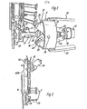
- the device shown in Fig. 1 consists essentially of a vertical magazine 1, in which a plurality of transport anchors 2 are stored one above the other in a manner described in more detail, an ejection device 3 movable transversely to the longitudinal axis of the transport anchor and one in the direction of the longitudinal axis of the transport anchor 2 movable carriage 4, which carries an openable and closable gripper 5 at the end facing the vertical magazine 1.
- Each transport anchor 2 is provided on its two end faces with a shoulder which is larger in diameter, as shown in FIGS. 2, 3 and 6 in particular.
- the approach lying within the concrete part, not shown, is larger than the approach gripped by the gripper 6 when it is introduced into the casting mold.
- the magazine 1 has two guides 6, 7 running in the vertical direction, which are arranged at a distance and in alignment with one another.
- Each guide 6, 7 is formed from two guide rails 8, 9 arranged at a distance from one another.
- the guide rails 8, 9 run parallel to one another and are firmly connected to one another via spacer bolts 10.
- the guides 6, 7 can be seen in the sense of a T-shaped guide. Strength in particular from F. 2 and 3 can be seen, the transport anchors 2 stored in the vertical magazine 1 protrude forward, that is, in the direction of the cutting 4.
- the vertical dimension Magazine provided with two roller chains 11, 12 running next to one another in the vertical direction, each of which is guided over two chain wheels 13, 14 arranged on a shaft in the upper and lower region of the vertical magazine 1.
- the upper sprockets 13 form the drive sprockets, which are driven by a gear motor 16 via a further chain 15 and a sprocket arranged on the same shaft.
- the geared motor 16 is connected in such a way that the strands of the roller chains 11, 12 facing / lying towards the transport anchors 2 are moved from top to bottom.
- the ejection device 3 consists of a slide 17, which is attached to the piston rod 18 of a stationary hydraulic cylinder 19.
- the slide 17 is guided in a guide 20 in a manner not explained in detail.
- an upwardly open receiving shell 21 is pivotally mounted on the slide 17.
- the pivot axis is designated 22.
- a return spring 23 is articulated above the pivot axis 22 on the receiving shell 21, the opposite end of which is articulated on the slide 17 above the piston rod 18.
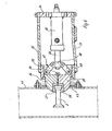
- the gripper 5 consists of two jaws 24, 25 which can be pivoted about a horizontal axis 26, the axis 26 lying opposite the jaw side, which in each case grips a transport anchor 2.
- the jaws 24, 25 are designed as solid bodies and, in the closed state, describe approximately the shape of a hemisphere.
- Each jaw 24, 25 is on the side opposite the axis 26 with one each Insert 27.28 provided, which is firmly inserted into corresponding recesses.
- Each insert 27, 28 is provided with a recess 29, 30, which extend to the edge facing away from the axis 26, and in the closed state of the jaws 24, 25 form a hollow chamber corresponding to the head shape of the transport anchor 2.
- the axis 26 is mounted with its two ends in a guide ring 31 in a rotationally fixed manner.
- the guide ring 31 on its inner side in the region of the end face facing the cutouts 29, 30 is a guide for the outer surfaces of the blocks 24, 25. This part is therefore designed in an arc shape.
- the guide ring 31 is worn white holding webs 32, 33 which are welded to the outside of the guide rings 31.
- the holding rods 32, 33 are fixedly arranged on the carriage 4 in a manner not explained in detail.
- the ends of the holding rods 32, 33 opposite the guide ring 31 are connected by means of a lug 34, so that the holding rods 32, 33 and the lug 34 form a U-shaped holder.
- a piston-cylinder unit 35 On the side facing the gripper 2, a piston-cylinder unit 35, in the present exemplary embodiment a hydraulic cylinder, is fastened to the tab 34, the piston rod 36 of which can be extended in the direction of the gripper 2, and carries an actuating linkage 37, which faces with it lying end faces of the jaws 24, 25 is articulated.
- the actuating linkage 37 consists of a bracket 38 fixedly attached to the piston rod 36 and two links 39, 40 arranged on the jaws 24, 25 so as to be rotatable.
- FIG. 5 shows a partial section of a casting mold 41 which, in the present exemplary embodiment, is designed for the production of concrete pipes.
- An opening 42 is provided in the outer wall into which a seal 43 attached to the mold 41 protrudes.
- 6 shows that by moving the slide, the jaws 24, 25 protrude into the mold 41 to a predetermined extent. However, the jaws 24, 25 were previously closed by extending the piston rod 36 of the piston-cylinder unit 35.
- the vertical magazine 1 To start up the device, the vertical magazine 1 must first be filled with transport anchors 2.
- the transport anchor 2 lying at the bottom is received by the receiving shell 21 for introduction into the casting mold 41.
- the piston rod 18 By acting on the piston of the hydraulic cylinder 19, the piston rod 18 is extended, as a result of which the transport anchor is aligned with the central longitudinal axis of the gripper 2. This position is shown in FIG. 3.
- the jaws 24, 25 are still open, but are closed shortly thereafter by extending the piston rod 36 of the piston-cylinder unit 35.
- the transport anchor 2 is then secure and held in place by the shape of the recesses 29,30.
- the receiving shell 21 is pivoted so that the slide 17 can return to the starting position by reversing the hydraulic cylinder 19.
- the return spring 23 causes the receiving shell 21 to pivot back.
- the lower transport anchor 2 located in the vertical magazine 1 rests on the return spring 23, so that further slipping is not possible.
- the carriage 4 and thus the gripper 5 and the transport anchor 2 located therein can be moved in the direction of the casting mold by a drive which is not explained in more detail.
- the mold can then be poured out with concrete. Since the seal 43 closes on the outside side of the jaws 24, 25, no concrete can run out of the mold 41. Since the jaws 24, 25 also protrude into the casting mold 41, a recess is created in the concrete part in order to later attach a rope or a chain when laying.
- the carriage 4 is moved so far that the lifting anchor 2 is flush with the outer surface of the concrete part, or protrudes only by a small amount in relation to the length.
- the jaws 24, 25 can be opened by reversing the piston-cylinder unit 35, since the longitudinal axis of the horizontal axis 26 forms the center of curvature for the jaws 24, 25.
- the carriage can be moved back to its starting position. The insertion process can then be started again.
- the gear motor 16 is switched on in the vertical magazine 1 to prevent the transport anchor from tilting.
- the roller chains 11, 12 rotate in the direction of the arrow A, and a tilted transport anchor 2 is also moved downward by frictional engagement.
Landscapes
- Engineering & Computer Science (AREA)
- Manufacturing & Machinery (AREA)
- Chemical & Material Sciences (AREA)
- Ceramic Engineering (AREA)
- Mechanical Engineering (AREA)
- Manufacturing Of Tubular Articles Or Embedded Moulded Articles (AREA)
- On-Site Construction Work That Accompanies The Preparation And Application Of Concrete (AREA)
- Devices For Post-Treatments, Processing, Supply, Discharge, And Other Processes (AREA)
- Forms Removed On Construction Sites Or Auxiliary Members Thereof (AREA)
Applications Claiming Priority (2)
| Application Number | Priority Date | Filing Date | Title |
|---|---|---|---|
| DE8409825U | 1984-03-30 | ||
| DE8409825U DE8409825U1 (de) | 1984-03-30 | 1984-03-30 | Vorrichtung zum Einbringen von Transportankern in eine Gießform für Betonteile |
Publications (1)
| Publication Number | Publication Date |
|---|---|
| EP0159551A1 true EP0159551A1 (fr) | 1985-10-30 |
Family
ID=6765340
Family Applications (1)
| Application Number | Title | Priority Date | Filing Date |
|---|---|---|---|
| EP85103464A Ceased EP0159551A1 (fr) | 1984-03-30 | 1985-03-23 | Dispositif pour introduire des ancres de transport dans un moule pour pièces en béton |
Country Status (6)
| Country | Link |
|---|---|
| US (1) | US4708612A (fr) |
| EP (1) | EP0159551A1 (fr) |
| AU (1) | AU4231785A (fr) |
| DE (1) | DE8409825U1 (fr) |
| NO (1) | NO854746L (fr) |
| WO (1) | WO1985004360A1 (fr) |
Cited By (1)
| Publication number | Priority date | Publication date | Assignee | Title |
|---|---|---|---|---|
| EP0230542A1 (fr) * | 1985-12-06 | 1987-08-05 | Georg Prinzing GmbH & Co. KG Betonformen- und Maschinenfabrik | Procédé et dispositif pour introduire et enrober de béton un boulon d'ancrage dans un élément en béton |
Families Citing this family (4)
| Publication number | Priority date | Publication date | Assignee | Title |
|---|---|---|---|---|
| DE3808379A1 (de) * | 1988-03-12 | 1989-09-28 | Detec Fertigung Gmbh | Vorrichtung zum einsetzen von transportankern in schalungen fuer betonteile |
| US5095615A (en) * | 1989-06-20 | 1992-03-17 | Samsung Electronics Co., Ltd. | Apparatus for transferring screw members |
| US5284375A (en) * | 1993-03-12 | 1994-02-08 | Ingersoll-Rand Company | Single actuation rod gripping mechanism |
| US5992123A (en) * | 1996-07-19 | 1999-11-30 | Erico International Corporation | Shear stud assembly and method for reinforcement of column or beam connections |
Citations (4)
| Publication number | Priority date | Publication date | Assignee | Title |
|---|---|---|---|---|
| DE1275278B (de) * | 1961-12-08 | 1968-08-14 | Fahr Ag Maschf | Vorrichtung zum Einlegen von Metallteilen in Pressformen von Pressautomaten, Pressen und Spritzgussmaschinen |
| US3423792A (en) * | 1964-03-11 | 1969-01-28 | Coats & Clark | Apparatus for feeding inserts from magazine to molding machine |
| DE2935825B1 (de) * | 1979-09-05 | 1980-12-04 | Ernst Dr-Ing Haeussler | Vorrichtung zur Erzeugung einer einen Ankerkopf konzentrisch umgebenden,etwa halbkugelfoermigen Aussparung in der Oberflaeche eines Stahlbetonfertigteiles |
| DE3219139A1 (de) * | 1982-05-21 | 1983-11-24 | DETEC Fertigung GmbH, 6080 Groß-Gerau | Verfahren und vorrichtung zum einsetzen von transportankern in betonfertigteile |
Family Cites Families (6)
| Publication number | Priority date | Publication date | Assignee | Title |
|---|---|---|---|---|
| US1818408A (en) * | 1926-08-27 | 1931-08-11 | Carolyn Laundry | Laundry tagging machine |
| US3501826A (en) * | 1967-04-21 | 1970-03-24 | Western Electric Co | Apparatus for assembling a pair of articles one within the other |
| US3543910A (en) * | 1968-07-30 | 1970-12-01 | George C Devol | Work-head automatic motions controls |
| US3543376A (en) * | 1968-08-21 | 1970-12-01 | Kaiser Gypsum Co | Apparatus for feeding and applying a spring clip to a workpiece |
| US3891014A (en) * | 1974-03-15 | 1975-06-24 | David T Gunn | Screw magazine mechanism for power screwdriver |
| JPS5639841A (en) * | 1979-08-31 | 1981-04-15 | Matsushita Electric Works Ltd | Automatic screw-driver for plate |
-
1984
- 1984-03-30 DE DE8409825U patent/DE8409825U1/de not_active Expired
-
1985
- 1985-03-23 US US06/809,920 patent/US4708612A/en not_active Expired - Fee Related
- 1985-03-23 EP EP85103464A patent/EP0159551A1/fr not_active Ceased
- 1985-03-23 WO PCT/EP1985/000127 patent/WO1985004360A1/fr unknown
- 1985-03-23 AU AU42317/85A patent/AU4231785A/en not_active Abandoned
- 1985-11-27 NO NO854746A patent/NO854746L/no unknown
Patent Citations (4)
| Publication number | Priority date | Publication date | Assignee | Title |
|---|---|---|---|---|
| DE1275278B (de) * | 1961-12-08 | 1968-08-14 | Fahr Ag Maschf | Vorrichtung zum Einlegen von Metallteilen in Pressformen von Pressautomaten, Pressen und Spritzgussmaschinen |
| US3423792A (en) * | 1964-03-11 | 1969-01-28 | Coats & Clark | Apparatus for feeding inserts from magazine to molding machine |
| DE2935825B1 (de) * | 1979-09-05 | 1980-12-04 | Ernst Dr-Ing Haeussler | Vorrichtung zur Erzeugung einer einen Ankerkopf konzentrisch umgebenden,etwa halbkugelfoermigen Aussparung in der Oberflaeche eines Stahlbetonfertigteiles |
| DE3219139A1 (de) * | 1982-05-21 | 1983-11-24 | DETEC Fertigung GmbH, 6080 Groß-Gerau | Verfahren und vorrichtung zum einsetzen von transportankern in betonfertigteile |
Cited By (1)
| Publication number | Priority date | Publication date | Assignee | Title |
|---|---|---|---|---|
| EP0230542A1 (fr) * | 1985-12-06 | 1987-08-05 | Georg Prinzing GmbH & Co. KG Betonformen- und Maschinenfabrik | Procédé et dispositif pour introduire et enrober de béton un boulon d'ancrage dans un élément en béton |
Also Published As
| Publication number | Publication date |
|---|---|
| WO1985004360A1 (fr) | 1985-10-10 |
| AU4231785A (en) | 1985-11-01 |
| DE8409825U1 (de) | 1984-06-28 |
| NO854746L (no) | 1985-11-27 |
| US4708612A (en) | 1987-11-24 |
Similar Documents
| Publication | Publication Date | Title |
|---|---|---|
| EP2173506B1 (fr) | Fermeture coulissante pour un récipient renfermant une fonte métallique | |
| DE2124784B2 (de) | Vorrichtung zum horizontalen ablegen von rohren | |
| DE3318851C2 (fr) | ||
| DE2458811A1 (de) | Vorrichtung zur handhabung eines fahrzeug-ladekuebels | |
| DE1265923B (de) | Giessvorrichtung | |
| DE3440172A1 (de) | Automatische zufuehrungseinrichtung fuer maschinen, die zum zerschneiden von metallstangen von rundem oder polygonalem querschnitt in stuecke dienen | |
| EP0244790B1 (fr) | Dispositif pour la fabrication d'armatures | |
| EP0159551A1 (fr) | Dispositif pour introduire des ancres de transport dans un moule pour pièces en béton | |
| DE2432770A1 (de) | Vorrichtung zur ueberfuehrung und gleichzeitigen querdurchtrennung im wesentlichen parallelepipedischer, noch unausgehaerteter porenleichtbetonkoerper | |
| DE3339115A1 (de) | Vorrichtung zum verlegen von pflastersteinen | |
| EP0408593B1 (fr) | Dispositif pour la fixation d'attaches de transport sur des coffrages pour elements en beton | |
| DE2205998A1 (de) | Trommelanlage zur oberflaechenbehandlung kleinerer metallgegenstaende | |
| DE2642313A1 (de) | Verfahren zum stapeln von masseln, insbesondere von ne-metall-barren, in uebereinandergeschichteten stapellagen von je vier masseln und vorrichtung zu dessen durchfuehrung | |
| DE3501845A1 (de) | Verfahren und vorrichtung zur formgebung von mit vorzugsweise mehreren abstehenden elementen, insbesondere steigelementen, wie steigeisen, steigbuegeln o.dgl. versehenen betonteilen, z.b. schachtringen, schachthaelsen o.dgl. | |
| DE6802369U (de) | Rollenabgabe-vorrichtung. | |
| DE19826462C1 (de) | Handhabungseinrichtung für Formen zur Herstellung von Schachtunterteilen aus Beton | |
| DE2049678A1 (de) | Verfahren und Vorrichtung zum Herausneh men eines gegossenen Gegenstandes aus einer mehrteiligen Form | |
| DE1031703B (de) | Vorrichtung zum Aufbringen von Sand oder anderem koernigen Material auf Ziegelsteine | |
| DE265392C (fr) | ||
| DE1934239U (de) | Dauerform-giessmaschine. | |
| DE281167C (fr) | ||
| DE2341388A1 (de) | Verteiler- und verdichterkoerper an einer maschine zur herstellung von formsteinen | |
| DE1174594B (de) | Zufuehreinrichtung an stangenverarbeitenden Werkzeugmaschinen | |
| DE4331517C2 (de) | Vorrichtung mit Öffnungs- und Schließeinrichtungen für mehrere auf einer Bodenplatte angeordnete Formwerkzeuge | |
| DE1456720C3 (de) | Vorrichtung zum Wenden von parallelflächigen Gegenständen |
Legal Events
| Date | Code | Title | Description |
|---|---|---|---|
| PUAI | Public reference made under article 153(3) epc to a published international application that has entered the european phase |
Free format text: ORIGINAL CODE: 0009012 |
|
| AK | Designated contracting states |
Designated state(s): AT BE CH DE FR GB IT LI LU NL SE |
|
| 17P | Request for examination filed |
Effective date: 19860429 |
|
| 17Q | First examination report despatched |
Effective date: 19870831 |
|
| RAP1 | Party data changed (applicant data changed or rights of an application transferred) |
Owner name: DEHA ANKERSYSTEME GMBH & CO. KG |
|
| STAA | Information on the status of an ep patent application or granted ep patent |
Free format text: STATUS: THE APPLICATION HAS BEEN REFUSED |
|
| 18R | Application refused |
Effective date: 19880804 |
|
| RIN1 | Information on inventor provided before grant (corrected) |
Inventor name: PAPE, HARALD |