EP0158795A2 - Clavier pour appareil électrique ou électronique - Google Patents
Clavier pour appareil électrique ou électronique Download PDFInfo
- Publication number
- EP0158795A2 EP0158795A2 EP85102105A EP85102105A EP0158795A2 EP 0158795 A2 EP0158795 A2 EP 0158795A2 EP 85102105 A EP85102105 A EP 85102105A EP 85102105 A EP85102105 A EP 85102105A EP 0158795 A2 EP0158795 A2 EP 0158795A2
- Authority
- EP
- European Patent Office
- Prior art keywords
- frame
- elements
- mounting frame
- openings
- control panel
- Prior art date
- Legal status (The legal status is an assumption and is not a legal conclusion. Google has not performed a legal analysis and makes no representation as to the accuracy of the status listed.)
- Granted
Links
Images
Classifications
-
- H—ELECTRICITY
- H02—GENERATION; CONVERSION OR DISTRIBUTION OF ELECTRIC POWER
- H02B—BOARDS, SUBSTATIONS OR SWITCHING ARRANGEMENTS FOR THE SUPPLY OR DISTRIBUTION OF ELECTRIC POWER
- H02B15/00—Supervisory desks or panels for centralised control or display
- H02B15/02—Supervisory desks or panels for centralised control or display with mimic diagrams
- H02B15/04—Supervisory desks or panels for centralised control or display with mimic diagrams consisting of building blocks
-
- H—ELECTRICITY
- H01—ELECTRIC ELEMENTS
- H01H—ELECTRIC SWITCHES; RELAYS; SELECTORS; EMERGENCY PROTECTIVE DEVICES
- H01H13/00—Switches having rectilinearly-movable operating part or parts adapted for pushing or pulling in one direction only, e.g. push-button switch
- H01H13/70—Switches having rectilinearly-movable operating part or parts adapted for pushing or pulling in one direction only, e.g. push-button switch having a plurality of operating members associated with different sets of contacts, e.g. keyboard
-
- H—ELECTRICITY
- H05—ELECTRIC TECHNIQUES NOT OTHERWISE PROVIDED FOR
- H05K—PRINTED CIRCUITS; CASINGS OR CONSTRUCTIONAL DETAILS OF ELECTRIC APPARATUS; MANUFACTURE OF ASSEMBLAGES OF ELECTRICAL COMPONENTS
- H05K7/00—Constructional details common to different types of electric apparatus
- H05K7/18—Construction of rack or frame
-
- H—ELECTRICITY
- H01—ELECTRIC ELEMENTS
- H01H—ELECTRIC SWITCHES; RELAYS; SELECTORS; EMERGENCY PROTECTIVE DEVICES
- H01H2223/00—Casings
- H01H2223/01—Mounting on appliance
- H01H2223/012—Snap mounting
-
- H—ELECTRICITY
- H01—ELECTRIC ELEMENTS
- H01H—ELECTRIC SWITCHES; RELAYS; SELECTORS; EMERGENCY PROTECTIVE DEVICES
- H01H2229/00—Manufacturing
- H01H2229/022—Modular assembly
-
- H—ELECTRICITY
- H01—ELECTRIC ELEMENTS
- H01H—ELECTRIC SWITCHES; RELAYS; SELECTORS; EMERGENCY PROTECTIVE DEVICES
- H01H2233/00—Key modules
- H01H2233/03—Key modules mounted on support plate or frame
- H01H2233/034—Snap coupling
Definitions
- the invention relates to a control panel for electrical or electronic devices with a plurality of display and / or actuation elements, comprising at least one grid-shaped mounting frame with a plurality of grid openings of the same size for receiving the display and / or actuation elements, each of which has a housing provided with latching elements , which can be clipped into a lattice opening in the mounting frame.
- Such a control panel has the advantage that the display and / or actuation elements can be used in a variety of ways and in a wide variety of arrangements in the mounting frame due to the standard dimensions of their housing, the mounting frame as a unit together with the display and / or actuation elements on one Front plate of a housing can be mounted. Grille openings of the mounting frame that are not required can be covered with suitable caps.
- the mounting frame located behind the front panel is screwed onto the front panel in such a way that only the display and operating elements pass through openings in the front panel.
- the invention has for its object to further simplify and standardize the assembly of the control panel and to enable a uniform design of the control panel of various devices even with different degrees of filling of the mounting frame with display and actuating elements.
- Mounting frames have latching elements, with the aid of which they can be clipped into the frame openings in the front plate of the device housing.
- the inventive solution the assembly is of the B edienungsfeldes further simplified since the assemblies thus formed are simply clipped into the frame openings of the front plate after insertion of the display and / or actuating elements in the assembly frame and after the connecting the elements to a circuit board.
- the frame openings are preferably of at least the same width, so that only a single embodiment of the mounting frame is required.
- n ötigten frame openings can be provided, which are also as the mounting frame with locking elements in the frame openings clipped cover. This allows the frame openings that are not required to be covered without significantly changing the overall appearance of the control panel.
- the covers can be designed as supports for type designations, names and the like.
- the locking elements on the mounting frame and / or cover elements are preferably each formed in one piece with the mounting frame or cover elements in the form of locking lugs or latches, which in the installed state of the mounting frame or cover elements engage behind an inner edge of the front plate surrounding the frame opening, while the assembly frame and support the cover elements on the outside of an edge surrounding the frame openings.
- the mounting frame acts simultaneously as a frame, so that, for example, a separate border around the subfield formed from the display elements and actuating elements of a mounting frame is omitted and the slots between the display and / or actuating elements and the edge of the frame openings are covered.
- this improves the appearance of the control panel and, on the other hand, prevents dust from entering these slots. This applies in particular to the case where individual lattice openings in the mounting frame are not equipped with display or actuation elements, but are only covered by blind caps.
- edges surrounding the frame openings in the front panel are preferably recessed in such a way that the outer surfaces of the mounting frame or cover elements are flush with the outer surface of the front panel when installed.
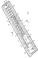
- the operating module shown in FIG. 1 comprises a front frame, generally designated 10, which can be connected to the housing of an electrical or electronic device in a manner not shown.
- the front frame 10 is shaped so that after its installation in the device housing, the control panel is inclined like a desk.
- the front frame 10 consists of two broad longitudinal sides 12 and 14, which are connected to one another by transverse webs 16, so that a series of frame openings 18 is formed, one of which. only two can be seen in FIG. 1.
- At least the dimensions of the frame openings transversely to the longitudinal direction of the front frame 10 are of the same size and are intended to accommodate a mounting frame (20) (FIG. 3).
- the mounting frame 20 in turn is designed to receive and hold display elements 22 and actuating elements 24.
- the rectangular mounting frame 20 consists of outer frame bars 26, between which a frame grille is provided by means of one or more longitudinal bars 28 and a plurality of transverse bars 30 square grid openings 32 is formed.
- the outer frame spars 26 and the webs 28 and 30 are preferably made in one piece from plastic.
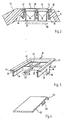
- latching pawls 34 engage with their latching lug 36 a holding surface 38 surrounding the frame opening 18 on the front frame 10 (FIG. 2).
- the handle of the latching pawl 34 is extended by incisions 40 in the frame bars 26.
- the frame spars 26 On their upper side, the frame spars 26 have an outwardly projecting edge 42, which forms a frame and is intended to rest on a step fold 44 surrounding the frame openings 18 in the front frame 10, the thickness of the frame 42 and the depth of the step fold 44 thus are coordinated with one another such that after the mounting frame 20 has been inserted into the front frame 10, the top of the mounting frame 20 is flush with the top of the front frame 10, as can be seen in FIG.
- a narrow circumferential strip 46 is formed which, together with strips 48 of the same cross section, is used on the longitudinal web 28 to hold the display and actuating elements 22 and 24 used in the mounting frame 20.
- the actual display elements and actuation elements are not shown. They are each in one ge Housing 50 is arranged with a square cross section, which is closed at the top by a diaphragm cap 52, which may have a window or a passage opening 54 for the actuating element, as can be seen in Figure 2.
- Notches form latching tongues 56 in two mutually opposite housing walls, which engage the strips 46 and 48 after inserting the housing 50 into a grid opening 32, as can be seen in FIG.
- the housing 50 rests with an edge 58 which is flush with the diaphragm cap 52. This can be connected to the housing 50 by latching means in a manner known per se.
- the grid openings 32 of the mounting frame 20 that are not required can be closed by blind caps, which are provided with locking elements corresponding to the housings 50 of the display and actuation elements.
- Frame openings 18, into which no mounting frame 20 is to be inserted, can be covered with a cover element 62, as shown in FIG. 4.
- the embodiment shown in do4 is an edge element that overlaps an end edge of the front frame 10 with a curved edge section 64, as can be seen in FIG.
- the cover element 62 has on its underside the latching pawls 34 corresponding latching elements 66, with which it can be latched in the front frame 10.
- the cover elements 62 can be designed in a suitable manner as carriers for type designations names or the like, as can be seen, for example, for the cover element 68 shown in FIG. 1 at the right end of the front frame 10. This has a recessed writing field 70 into which a suitable writing tablet, sign or the like can be inserted.
- control module according to the invention is extremely easy to assemble. If it is necessary to remove, replace or supplement display elements or actuating elements, the removal of the mounting frame from the front frame 10 is extremely simple.
- the locking pawls 34 are pressed inwards and the mounting frame 20 is pressed outwards out of the locking openings 13. After unsoldering the connections of the display elements and actuating elements, these can also be removed from the respective mounting frame 20 by pressing in the latching tongues 56.
Applications Claiming Priority (2)
| Application Number | Priority Date | Filing Date | Title |
|---|---|---|---|
| DE8410365U DE8410365U1 (de) | 1984-04-03 | 1984-04-03 | Bedienungsfeld für elektrische und elektronische Geräte |
| DE8410365U | 1984-04-03 |
Publications (3)
| Publication Number | Publication Date |
|---|---|
| EP0158795A2 true EP0158795A2 (fr) | 1985-10-23 |
| EP0158795A3 EP0158795A3 (en) | 1986-05-14 |
| EP0158795B1 EP0158795B1 (fr) | 1989-01-18 |
Family
ID=6765507
Family Applications (1)
| Application Number | Title | Priority Date | Filing Date |
|---|---|---|---|
| EP85102105A Expired EP0158795B1 (fr) | 1984-04-03 | 1985-02-26 | Clavier pour appareil électrique ou électronique |
Country Status (2)
| Country | Link |
|---|---|
| EP (1) | EP0158795B1 (fr) |
| DE (2) | DE8410365U1 (fr) |
Cited By (8)
| Publication number | Priority date | Publication date | Assignee | Title |
|---|---|---|---|---|
| EP0354340A2 (fr) * | 1988-08-12 | 1990-02-14 | Digital-Kienzle Computersysteme GmbH & Co. KG | Clavier |
| FR2686214A1 (fr) * | 1992-01-14 | 1993-07-16 | Aerospatiale | Systeme de montage sur un element fixe d'un element amovible portant une pluralite de dispositifs electriques. |
| EP0713314A2 (fr) * | 1990-02-15 | 1996-05-22 | Hitachi Telecom Technologies, Ltd. | Pupitre de transaction |
| WO1997031557A1 (fr) * | 1996-02-26 | 1997-09-04 | Robert Duscher | Cadre de montage pour appareils encastres dans des pupitres de commande et de travail |
| EP0841673A2 (fr) * | 1996-11-12 | 1998-05-13 | Molex Incorporated | Module de commutation électrique |
| WO1998050930A1 (fr) * | 1997-05-07 | 1998-11-12 | Marquardt Gmbh | Ensemble de commutateurs |
| DE19723403A1 (de) * | 1997-06-04 | 1998-12-10 | Eaton Gmbh | Gehäuse für ein mit einem Display versehenen elektrisches Gerät, insbesondere eine Herdschaltuhr |
| WO2020187974A1 (fr) * | 2019-03-18 | 2020-09-24 | Minimax Viking Research & Development Gmbh | Composant porteur d'un boîtier d'une centrale d'alarme de dangers et centrale d'alarme de dangers, de préférence d'une centrale d'alarme d'infraction, d'incendie et/ou d'une centrale de commande d'extinction |
Families Citing this family (1)
| Publication number | Priority date | Publication date | Assignee | Title |
|---|---|---|---|---|
| DE4019837A1 (de) * | 1990-06-21 | 1992-01-09 | Grothe & Soehne Kg A | Tueranlage, insbesondere tuersprechanlage |
Citations (3)
| Publication number | Priority date | Publication date | Assignee | Title |
|---|---|---|---|---|
| DE2713307A1 (de) * | 1976-05-13 | 1977-11-24 | Ebco Ind Ltd | Gehaeuse |
| DE2902052A1 (de) * | 1979-01-19 | 1980-07-24 | Siemens Ag | Elektrisches geraet, insbesondere fernsprechgeraet, mit einem einen hohlraum umschliessenden gehaeuse |
| GB2086804A (en) * | 1980-11-04 | 1982-05-19 | Standard Telephones Cables Ltd | Keyblock assembly |
-
1984
- 1984-04-03 DE DE8410365U patent/DE8410365U1/de not_active Expired
-
1985
- 1985-02-26 EP EP85102105A patent/EP0158795B1/fr not_active Expired
- 1985-02-26 DE DE8585102105T patent/DE3567789D1/de not_active Expired
Patent Citations (3)
| Publication number | Priority date | Publication date | Assignee | Title |
|---|---|---|---|---|
| DE2713307A1 (de) * | 1976-05-13 | 1977-11-24 | Ebco Ind Ltd | Gehaeuse |
| DE2902052A1 (de) * | 1979-01-19 | 1980-07-24 | Siemens Ag | Elektrisches geraet, insbesondere fernsprechgeraet, mit einem einen hohlraum umschliessenden gehaeuse |
| GB2086804A (en) * | 1980-11-04 | 1982-05-19 | Standard Telephones Cables Ltd | Keyblock assembly |
Non-Patent Citations (1)
| Title |
|---|
| IBM TECHNICAL DISCLOSURE BULLETIN, Band 5, Nr. 2, Juli 1962, Seiten 46-47, New York, US; A.T. HARDARDT et al: "Plastic component housing" * |
Cited By (14)
| Publication number | Priority date | Publication date | Assignee | Title |
|---|---|---|---|---|
| EP0354340A2 (fr) * | 1988-08-12 | 1990-02-14 | Digital-Kienzle Computersysteme GmbH & Co. KG | Clavier |
| EP0354340A3 (fr) * | 1988-08-12 | 1991-05-15 | Digital-Kienzle Computersysteme GmbH & Co. KG | Clavier |
| EP0713314A2 (fr) * | 1990-02-15 | 1996-05-22 | Hitachi Telecom Technologies, Ltd. | Pupitre de transaction |
| EP0713314A3 (fr) * | 1990-02-15 | 1996-09-11 | Hitachi Telecomm Tech | Pupitre de transaction |
| FR2686214A1 (fr) * | 1992-01-14 | 1993-07-16 | Aerospatiale | Systeme de montage sur un element fixe d'un element amovible portant une pluralite de dispositifs electriques. |
| WO1997031557A1 (fr) * | 1996-02-26 | 1997-09-04 | Robert Duscher | Cadre de montage pour appareils encastres dans des pupitres de commande et de travail |
| EP0841673A2 (fr) * | 1996-11-12 | 1998-05-13 | Molex Incorporated | Module de commutation électrique |
| EP0841673A3 (fr) * | 1996-11-12 | 1998-12-30 | Molex Incorporated | Module de commutation électrique |
| WO1998050930A1 (fr) * | 1997-05-07 | 1998-11-12 | Marquardt Gmbh | Ensemble de commutateurs |
| US6204459B1 (en) | 1997-05-07 | 2001-03-20 | Marquardt Gmbh | Switching arrangement |
| DE19723403A1 (de) * | 1997-06-04 | 1998-12-10 | Eaton Gmbh | Gehäuse für ein mit einem Display versehenen elektrisches Gerät, insbesondere eine Herdschaltuhr |
| DE19723403B4 (de) * | 1997-06-04 | 2012-04-05 | Siebe Appliance Controls Gmbh | Gehäuse für ein mit einem Display versehenen elektrisches Gerät, insbesondere eine Herdschaltuhr |
| WO2020187974A1 (fr) * | 2019-03-18 | 2020-09-24 | Minimax Viking Research & Development Gmbh | Composant porteur d'un boîtier d'une centrale d'alarme de dangers et centrale d'alarme de dangers, de préférence d'une centrale d'alarme d'infraction, d'incendie et/ou d'une centrale de commande d'extinction |
| US11922795B2 (en) | 2019-03-18 | 2024-03-05 | Minimax Viking Research & Development Gmbh | Support component of a housing of a hazard alert center and a hazard alert center, preferably an intruder alert, fire alarm and/or extinguishing control center |
Also Published As
| Publication number | Publication date |
|---|---|
| DE3567789D1 (en) | 1989-02-23 |
| DE8410365U1 (de) | 1984-06-20 |
| EP0158795A3 (en) | 1986-05-14 |
| EP0158795B1 (fr) | 1989-01-18 |
Similar Documents
| Publication | Publication Date | Title |
|---|---|---|
| DE3318135C2 (fr) | ||
| DE102004031707B4 (de) | Intelligenter Anschlusskasten für Kraftfahrzeuge | |
| DE4241876C2 (de) | Einschub-/Entnahmevorrichtung für Schaltungsplatinen | |
| DE3238750C1 (de) | Schaltkarte | |
| EP0134540A1 (fr) | Blindage contre des rayonnements à haute fréquence de surfaces planes | |
| EP0158795B1 (fr) | Clavier pour appareil électrique ou électronique | |
| DE102011013180A1 (de) | Bauteil für eine Tastenanordnung einer Bedienblende | |
| EP1282345A2 (fr) | Boítier abritant une carte électronique avec ses composants dans un véhicule | |
| EP0167478B1 (fr) | Boîtier unique permettant par arrangement une construction modulaire | |
| EP0221201A1 (fr) | Boîtier pour circuits électriques et électroniques | |
| EP0313131A2 (fr) | Dispositif de logement de cartes blindées | |
| DE3543885C1 (en) | Switch unit, especially for motor vehicles | |
| EP1376802A1 (fr) | Châssis de couvercle pour un appareil d'installation électrique | |
| DE2515742C3 (de) | Gehäuse für ein kontaktloses elektrisches Gerät | |
| DE3308510C2 (de) | Gehäuse für elektrische und/oder elektronische auf Leiterplatten angeordnete Bauelemente | |
| DE2100879C3 (de) | Kassettenschild | |
| DE10038821A1 (de) | Lüftungsgitter | |
| DE1275170B (de) | Modulbau fuer integrierte, elektronische Schaltungen | |
| WO2013143930A1 (fr) | Module de système destiné au génie électrique d'immeubles et au génie des systèmes portiers de communication | |
| DE3202043A1 (de) | Relais, insbesondere leiterplattenrelais | |
| DE3326906C2 (de) | Weidezaungerät | |
| DE19833248A1 (de) | Vorrichtung zum Führen und Massekontaktieren von Leiterplatten | |
| EP1052752B1 (fr) | Dispositif pour recevoir au moins deux composants électriques, tels que socles , interrupteurs, unités électroniques ou similaires | |
| DE19932419A1 (de) | Abschirmanordnung | |
| DE7707997U1 (de) | Gehäusebausatz für elektrische Geräte, insbesondere von Sprech- und/oder Klingelanlagen |
Legal Events
| Date | Code | Title | Description |
|---|---|---|---|
| PUAI | Public reference made under article 153(3) epc to a published international application that has entered the european phase |
Free format text: ORIGINAL CODE: 0009012 |
|
| AK | Designated contracting states |
Designated state(s): AT BE CH DE FR GB IT LI LU NL SE |
|
| RBV | Designated contracting states (corrected) |
Designated state(s): DE FR GB IT SE |
|
| PUAL | Search report despatched |
Free format text: ORIGINAL CODE: 0009013 |
|
| AK | Designated contracting states |
Kind code of ref document: A3 Designated state(s): DE FR GB IT SE |
|
| 17P | Request for examination filed |
Effective date: 19861103 |
|
| 17Q | First examination report despatched |
Effective date: 19880706 |
|
| GRAA | (expected) grant |
Free format text: ORIGINAL CODE: 0009210 |
|
| AK | Designated contracting states |
Kind code of ref document: B1 Designated state(s): DE FR GB IT SE |
|
| REF | Corresponds to: |
Ref document number: 3567789 Country of ref document: DE Date of ref document: 19890223 |
|
| GBT | Gb: translation of ep patent filed (gb section 77(6)(a)/1977) | ||
| ITF | It: translation for a ep patent filed |
Owner name: MODIANO & ASSOCIATI S.R.L. |
|
| ET | Fr: translation filed | ||
| PLBE | No opposition filed within time limit |
Free format text: ORIGINAL CODE: 0009261 |
|
| STAA | Information on the status of an ep patent application or granted ep patent |
Free format text: STATUS: NO OPPOSITION FILED WITHIN TIME LIMIT |
|
| 26N | No opposition filed | ||
| ITTA | It: last paid annual fee | ||
| ITPR | It: changes in ownership of a european patent |
Owner name: CAMBIO RAGIONE SOCIALE;SIEMENS NIXDORF INFORMATION |
|
| REG | Reference to a national code |
Ref country code: FR Ref legal event code: CD |
|
| PGFP | Annual fee paid to national office [announced via postgrant information from national office to epo] |
Ref country code: SE Payment date: 19930218 Year of fee payment: 9 |
|
| PGFP | Annual fee paid to national office [announced via postgrant information from national office to epo] |
Ref country code: GB Payment date: 19940124 Year of fee payment: 10 |
|
| PGFP | Annual fee paid to national office [announced via postgrant information from national office to epo] |
Ref country code: FR Payment date: 19940224 Year of fee payment: 10 |
|
| PG25 | Lapsed in a contracting state [announced via postgrant information from national office to epo] |
Ref country code: SE Effective date: 19940227 |
|
| PGFP | Annual fee paid to national office [announced via postgrant information from national office to epo] |
Ref country code: DE Payment date: 19940419 Year of fee payment: 10 |
|
| EUG | Se: european patent has lapsed |
Ref document number: 85102105.5 Effective date: 19940910 |
|
| PG25 | Lapsed in a contracting state [announced via postgrant information from national office to epo] |
Ref country code: GB Effective date: 19950226 |
|
| GBPC | Gb: european patent ceased through non-payment of renewal fee |
Effective date: 19950226 |
|
| PG25 | Lapsed in a contracting state [announced via postgrant information from national office to epo] |
Ref country code: FR Effective date: 19951031 |
|
| PG25 | Lapsed in a contracting state [announced via postgrant information from national office to epo] |
Ref country code: DE Effective date: 19951101 |
|
| REG | Reference to a national code |
Ref country code: FR Ref legal event code: ST |