EP0155067A2 - Mühle für Carbon Black - Google Patents
Mühle für Carbon Black Download PDFInfo
- Publication number
- EP0155067A2 EP0155067A2 EP85300319A EP85300319A EP0155067A2 EP 0155067 A2 EP0155067 A2 EP 0155067A2 EP 85300319 A EP85300319 A EP 85300319A EP 85300319 A EP85300319 A EP 85300319A EP 0155067 A2 EP0155067 A2 EP 0155067A2
- Authority
- EP
- European Patent Office
- Prior art keywords
- gas stream
- set forth
- predetermined velocity
- impact
- locus
- Prior art date
- Legal status (The legal status is an assumption and is not a legal conclusion. Google has not performed a legal analysis and makes no representation as to the accuracy of the status listed.)
- Granted
Links
- 239000006229 carbon black Substances 0.000 title claims description 22
- 239000002245 particle Substances 0.000 claims abstract description 24
- 239000011236 particulate material Substances 0.000 claims description 13
- 239000012535 impurity Substances 0.000 claims description 5
- 239000012530 fluid Substances 0.000 claims description 2
- 239000007789 gas Substances 0.000 description 37
- 239000013618 particulate matter Substances 0.000 description 6
- 230000008901 benefit Effects 0.000 description 5
- 238000010276 construction Methods 0.000 description 5
- 230000000694 effects Effects 0.000 description 5
- 239000011449 brick Substances 0.000 description 4
- 238000006073 displacement reaction Methods 0.000 description 4
- 239000000463 material Substances 0.000 description 4
- 239000000470 constituent Substances 0.000 description 3
- 238000000034 method Methods 0.000 description 3
- 239000002006 petroleum coke Substances 0.000 description 3
- 230000009467 reduction Effects 0.000 description 3
- 238000013459 approach Methods 0.000 description 2
- 238000006243 chemical reaction Methods 0.000 description 2
- 239000000571 coke Substances 0.000 description 2
- 239000000356 contaminant Substances 0.000 description 2
- 230000003116 impacting effect Effects 0.000 description 2
- 238000004519 manufacturing process Methods 0.000 description 2
- 239000003921 oil Substances 0.000 description 2
- 239000011343 solid material Substances 0.000 description 2
- 239000004215 Carbon black (E152) Substances 0.000 description 1
- 230000035508 accumulation Effects 0.000 description 1
- 238000009825 accumulation Methods 0.000 description 1
- 230000009471 action Effects 0.000 description 1
- 230000005540 biological transmission Effects 0.000 description 1
- 238000001311 chemical methods and process Methods 0.000 description 1
- 238000000576 coating method Methods 0.000 description 1
- 230000002708 enhancing effect Effects 0.000 description 1
- 238000001914 filtration Methods 0.000 description 1
- 230000005484 gravity Effects 0.000 description 1
- 229930195733 hydrocarbon Natural products 0.000 description 1
- 150000002430 hydrocarbons Chemical class 0.000 description 1
- 230000006872 improvement Effects 0.000 description 1
- 230000004048 modification Effects 0.000 description 1
- 238000012986 modification Methods 0.000 description 1
- 238000012545 processing Methods 0.000 description 1
- 238000010298 pulverizing process Methods 0.000 description 1
- -1 scale Substances 0.000 description 1
- 238000007789 sealing Methods 0.000 description 1
- 238000000926 separation method Methods 0.000 description 1
- 239000007790 solid phase Substances 0.000 description 1
- 238000012546 transfer Methods 0.000 description 1
Images
Classifications
-
- B—PERFORMING OPERATIONS; TRANSPORTING
- B02—CRUSHING, PULVERISING, OR DISINTEGRATING; PREPARATORY TREATMENT OF GRAIN FOR MILLING
- B02C—CRUSHING, PULVERISING, OR DISINTEGRATING IN GENERAL; MILLING GRAIN
- B02C13/00—Disintegrating by mills having rotary beater elements ; Hammer mills
- B02C13/26—Details
- B02C13/288—Ventilating, or influencing air circulation
-
- B—PERFORMING OPERATIONS; TRANSPORTING
- B02—CRUSHING, PULVERISING, OR DISINTEGRATING; PREPARATORY TREATMENT OF GRAIN FOR MILLING
- B02C—CRUSHING, PULVERISING, OR DISINTEGRATING IN GENERAL; MILLING GRAIN
- B02C13/00—Disintegrating by mills having rotary beater elements ; Hammer mills
- B02C13/26—Details
- B02C13/286—Feeding or discharge
Definitions
- This invention relates to a method and apparatus for enhancing the fineness of oversized particulate matter entrained in a gas stream by impact with rapidly rotating ' hammer surfaces and more particularly to a method and apparatus for reducing the size of minor fractions of oversized particulates entrained in a gas borne stream of carbon black or the like.
- hammer mills Impact pulverization of particulate matter has long been conventionally effected by impaction techniques in apparatus generally delineated as "hammer mills".
- hammer mills While of widely varying construction and nomenclature, normally employ a plurality of rapidly advancing hammer member or other particle impacting members peripherally mounted on a high speed rotor with cooperating means to introduce the solid material to be comminuted into the path of which rapidly moving hammer members.
- Such solid material usually in the form of large size particulates is conventionally fed into the hammer path by gravity or by conveyors or, in some instances, by air stream and generally in a direction normal to the tangential motion of the rotating hammer faces in order to obtain maximum velocity differentials and/or maximum energy transfer between the moving hammer faces and the material to be comminuted.
- hammer mills While such hammer mills are widely used for the comminution of materials, they are not particularly well adapted to efficiently effect the selective reduction of minor fractions of oversized particulates entrained in a gas borne stream of preformed or precomminuted particulate matter. While the presence of minor fractions of oversized particulate material will normally be found, in varying degree, in the output gas stream from conventional hammer mills, the presence of such oversize particulates is particularly troublesome in the processing of carbon black since such oversized particulates are there normally in the nature of undesired inpurities, such as scale, brick or other reaction vessel materials and/or coke particulates, therein and their oversize results in certain problems when the carbon black product is later used in diverse physical and chemical processes.
- the subject invention may be considered as an improved radial flow impactor-separator unit into which a particulate material is introduced essentially tangential to and codirectionally with the direction of impact member advance.
- the codirectional flow aspect of this invention is contrary to conventional teaching. It is conventionally thought that in order to maximize impact energy it is desirable to feed such a particulate bearing gas stream in a direction opposite that of impact member advance.
- the present inventor has determined, however, that if the tip speed of the rotor is sufficiently greater than the speed of the gas, the losses of impact energy due to the codirectionality of the collisions are not important. This is because the Impact Energy is proportional to the square of the velocity of the rotor tips minus the square of the velocity of the gas. Thus, as long as the difference in the two velocities is sufficient, the energy of the collision provide sufficient impact engergy.
- the subject invention includes a radial flow impactor-separator unit into which particulate bearing gas stream bearing a minor fraction of oversized particulate material is introduced into an impactor zone at a high velocity, as for example at 5000 at 8000 ft./min., and under turbulent flow conditions and within which zone the particle impacting surfaces are advancing at at least twice the speed of the incoming gas stream and desirably at a differential velocity therebetween of at least about 10,000 to 12,000 ft./min.
- a particular advantage attendant the use of the subject invention is the improvement of utility and commercial value of carbon black product through the selective reduction of the size of oversized impurities often found therein, such as particles of brick, scale, or petroleum coke, that emanate from the reactor vessels together with the carbon black products in the exit gas stream therefrom.
- a corollary advantage thereto is a permitted extension of the useful life of carbon black production reactor vessels.
- a further advantage of the subject invention is the minimization, if not avoidance, of coatings or other undersired accumulations of the finer sized particulates, specifically carbon black, within the impactor-separator and attendant high operational efficiency thereof.
- the primary object of this invention is the provision of an improved construction for a radial flow impactor-separator device for effecting the selective comminution of minor fractions of oversized particulate material in a stream of gas borne particulates.
- Another primary object of this invention is the provision of an improved construction for a radial flow impactor-separator device for effecting the selective comminution of oversized particulate material in a gas borne stream of carbon black.
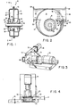
- a housing in the form of an entry volute shell 12 and exit volute shell 14 disposed in back to back relation and separated by a central wall 16 having a circular aperture 18 therein.
- a drive shaft 20 is mounted in suitable shell supported bearings 22 and 24 and coaxially traverses the opening 18 in central wall 16.
- a rotor 28 Mounted on shaft 20 within the entry volute chamber 26, as such is defined by volute shell 12 and central wall 16, is a rotor 28 having a plurality of hammer members 30 perpendi-cularly mounted on the periphery thereof.
- the free terminal ends of the hammer members 30 are disposed closely adjacent to the marginal facing surface of the portion of the central wall 16 defining the opening 18 therein and the path of rotative displacement thereof is peripherally bounded by a pair of outwardly extending sealing ridges or shoulders 32 thereon to minimize undesired gas and material flow past the hammer member ends.
- This feature is particularly aimed at minimizing the flow of large impurity particulates.
- the surface of the rotor base 28 disposed in spaced facing relation to the opening 18 is arcuately shaped, as at 34, to enhance a selectively directed gas flow from the interior side of the hammer members 30 to and through such opening 18.
- the entry volute chamber 26 is provided with a tangential inlet conduit 36 having a flanged terminal end 38 and a plurality of adjustable vanes 40 to permit control of the angle of entry of the incomings gas stream.
- a fan assembly including an arcuately contoured hub 52 and a plurality of radially mounted blade members 54 volute chamber 50 is provided with a tangential outlet conduit 56 having a flanged terminal end 58.
- an intake gas stream bearing a minor fraction of oversized particulate matter is adapted to be introduced at high velocity into the entry volute chamber 26 through intake conduit 36.
- the gas stream velocity and hammer member 30 velocities are of such relative magnitude as to effect selective impaction and comminution of the oversized particulates as the latter are induced to flow, together with the gas stream, through the entry volute chamber 26, the comminution zone as defined by the locus of rotative displacement of the hammer members 30, the central opening 18, the exit volute chamber 50 and the outlet conduit 56.
- the incoming oversize particulate bearing gas stream is desirably introduced into inlet conduit 36 at velocities in the order of 5000 to 8000 feet per minute under turbulent flow conditions and with the hammer members 30 being advanced at at least twice the speed of the incoming gas stream and preferably at a differential velocity therebetween of about 10,000 to 12,000 ft./min.
- the subject invention appears to be possessed of particular utility in the production of a high quality carbon black product.
- impurities in the form of oversized particles of scale, brick, petroleum coke and the like become entrained in the exiting gas stream bearing the desired carbon black product.
- Petroleum coke particles vary with the quality of the hydrocarbon feed stocks, said particles being a greater problem with Mexican, Canadian and some U.S. oil, than with the Arabian oils.
- the presence of these undesired oversized contaminants even when constituting a very minor constituent thereof, result in a substantial diminution of both product utility and its commercial value. Reducing the size of these impurity particles greatly increases the utility of the carbon black product.
- optional back out means may be provided.
- Said back out means are intended to intercept and remove particularly hard to grind particles.
- Said back out means may take the form of an auger like back out screw, or, as shown, may be in the form of a paddle type air lock.
- Paddles 61 are mounted on a cylindrical hub 62, and the assemblage thereof rotates in chamber 63. Particularly heavy particles sliding along the periphery of the volute will enter the airlock at 64, where the rotating paddles 61 will sweep the particles towards the exit at 65.
- an impactor-separator assembly generally designated 70 and of the character described above, as employed in conjunction with the effluent gas stream from a carbon black reaction, wherein the drive shaft 20 is driven, through transmission 72 by an electric motor 74, suitably a high horsepower AC motor.
- the exhaust duct 76 of a carbon black reactor of conventional construction (not shown) is connected to the inlet conduit 36 of the entry volute chamber 26.
- the incoming gas stream constitutes a multiphase fluid made up of the carbon black reactor exhaust gases and a solid phase principally constituted by finely divided carbon black particles and a minor constituent or fraction of oversized particulate contaminants primarily in the form of particles of scale, brick, coke or the like.
- Such effluent gas flow is moved at a high velocity, suitably in the order of 5000 to 8000 ft./min. through the duct 76 under the impetus of the positive pressure extant within the reactor exhaust system and/or the inducement of the rapidly rotating fan blades 54 in the exit volute chamber 50.
- the exhaust duct 76 of the carbon black reactor is of sufficient length as for example at least about 10 feet, to permit the velocity of the entrained carbon black particles to closely approach the velocity of the gas stream by the time such particles approach the inlet conduit 36 to the entry volute chamber 26.
- the gas stream assumes a more or less spiral but highly turbulent path in a direction generally concurrent to the direction of rotation of the laminar members 30.
- rotation of the hammer members 30 at a speed of at least twice that of the gas stream and desirably at a speed differential of from 10,000 to 12,000 ft./min. at the locus of impact effects a selective comminution of the oversize particulates as the gas stream passes through the locus of hammer member displacement without any noticeable effect upon the main carbon black particulate constituent also being borne by said gas stream.
- the gas stream and the particulate matter being carried thereby is directed through the opening 18 and, under the action of the rotating fan blades 54 and exit volute chamber 50 into an outwardly directed spiral path for discharge through outlet conduit 56 to a baghouse collector or other suitable filtering device to separate the particulate matter from the gas stream.
Landscapes
- Engineering & Computer Science (AREA)
- Food Science & Technology (AREA)
- Crushing And Pulverization Processes (AREA)
- Pigments, Carbon Blacks, Or Wood Stains (AREA)
- Pharmaceuticals Containing Other Organic And Inorganic Compounds (AREA)
- Carbon And Carbon Compounds (AREA)
Priority Applications (1)
| Application Number | Priority Date | Filing Date | Title |
|---|---|---|---|
| AT85300319T ATE58310T1 (de) | 1984-03-13 | 1985-01-17 | Muehle fuer carbon black. |
Applications Claiming Priority (2)
| Application Number | Priority Date | Filing Date | Title |
|---|---|---|---|
| US06/589,130 US4600156A (en) | 1984-03-13 | 1984-03-13 | Carbon black mill |
| US589130 | 1991-08-30 |
Publications (3)
| Publication Number | Publication Date |
|---|---|
| EP0155067A2 true EP0155067A2 (de) | 1985-09-18 |
| EP0155067A3 EP0155067A3 (en) | 1986-12-03 |
| EP0155067B1 EP0155067B1 (de) | 1990-11-14 |
Family
ID=24356722
Family Applications (1)
| Application Number | Title | Priority Date | Filing Date |
|---|---|---|---|
| EP85300319A Expired - Lifetime EP0155067B1 (de) | 1984-03-13 | 1985-01-17 | Mühle für Carbon Black |
Country Status (6)
| Country | Link |
|---|---|
| US (1) | US4600156A (de) |
| EP (1) | EP0155067B1 (de) |
| JP (1) | JPS60212248A (de) |
| AT (1) | ATE58310T1 (de) |
| CA (1) | CA1236809A (de) |
| DE (1) | DE3580499D1 (de) |
Family Cites Families (23)
| Publication number | Priority date | Publication date | Assignee | Title |
|---|---|---|---|---|
| US1673465A (en) * | 1927-07-05 | 1928-06-12 | Wilson L Mclaughlin | Pulverizing machine |
| US2039264A (en) * | 1933-08-15 | 1936-04-28 | Jeffrey Mfg Co | Apparatus for breaking down material |
| DE637713C (de) * | 1936-01-17 | 1937-06-02 | Kohlenscheidungs Ges M B H | Schlaegermuehle |
| US2253733A (en) * | 1938-03-31 | 1941-08-26 | Impact pulverizer | |
| US2212482A (en) * | 1938-06-02 | 1940-08-20 | Louis Ruprecht | Reducing mill |
| US2226330A (en) * | 1938-10-14 | 1940-12-24 | Nordberg Manufacturing Co | Impact crusher |
| US2316124A (en) * | 1940-08-01 | 1943-04-06 | Louis Ruprecht | Apparatus for impact pulverizing |
| US2319192A (en) * | 1941-07-21 | 1943-05-11 | Louis Ruprecht | Pulverizing mill |
| GB576965A (en) * | 1944-07-11 | 1946-04-29 | Babcock & Wilcox Ltd | Improvements in pulverising mills |
| US2543599A (en) * | 1946-04-06 | 1951-02-27 | Rietz Mfg Co | Screen structure for hammer mills |
| US2588434A (en) * | 1949-06-16 | 1952-03-11 | Frank P Unti | Impact bar assembly for impeller breakers |
| US2644644A (en) * | 1951-06-08 | 1953-07-07 | Pennsylvania Crusher Co | Two stage hammer mill |
| US2706088A (en) * | 1952-01-16 | 1955-04-12 | Emil H Paul | Rotary cake breaker |
| DE1077948B (de) * | 1958-08-07 | 1960-03-17 | E H Ehrhardt Andreas Dr Ing | Schleuderprallmuehle zum Aufbereiten von Massengut, insbesondere Asbestgestein |
| GB876418A (en) * | 1959-12-30 | 1961-08-30 | Hosokawa Tekkosho Kk | Improvements in pulverizer-separators |
| US3285523A (en) * | 1964-02-17 | 1966-11-15 | Slick Ind Company | Comminuting apparatus |
| US3333777A (en) * | 1965-04-19 | 1967-08-01 | Higfill | Grinding mill |
| DE1507601A1 (de) * | 1966-07-04 | 1969-07-24 | Wilh Ley Maschf | Hammermuehle |
| US3610542A (en) * | 1967-10-11 | 1971-10-05 | Takashi Yamagishi | Pulverizer |
| DE2614552A1 (de) * | 1976-04-03 | 1977-10-13 | Kloeckner Humboldt Deutz Ag | Zerkleinerungsmaschine mit einem zerkleinerungsrotor |
| US4200241A (en) * | 1977-08-08 | 1980-04-29 | Bepex Corporation | Pulverizing and classifying apparatus with contaminant take-out |
| DE2912954C2 (de) * | 1979-03-31 | 1981-05-21 | Evt Energie- Und Verfahrenstechnik Gmbh, 7000 Stuttgart | Schlagradmühle |
| GB2061762B (en) * | 1979-10-30 | 1983-03-30 | British Rema Mfg Co Ltd | Pulverizing and classifying mill |
-
1984
- 1984-03-13 US US06/589,130 patent/US4600156A/en not_active Expired - Fee Related
-
1985
- 1985-01-17 EP EP85300319A patent/EP0155067B1/de not_active Expired - Lifetime
- 1985-01-17 AT AT85300319T patent/ATE58310T1/de not_active IP Right Cessation
- 1985-01-17 DE DE8585300319T patent/DE3580499D1/de not_active Expired - Fee Related
- 1985-01-24 CA CA000472752A patent/CA1236809A/en not_active Expired
- 1985-03-13 JP JP60050247A patent/JPS60212248A/ja active Granted
Also Published As
| Publication number | Publication date |
|---|---|
| US4600156A (en) | 1986-07-15 |
| EP0155067A3 (en) | 1986-12-03 |
| EP0155067B1 (de) | 1990-11-14 |
| CA1236809A (en) | 1988-05-17 |
| JPS60212248A (ja) | 1985-10-24 |
| JPH0513712B2 (de) | 1993-02-23 |
| ATE58310T1 (de) | 1990-11-15 |
| DE3580499D1 (de) | 1990-12-20 |
Similar Documents
| Publication | Publication Date | Title |
|---|---|---|
| KR890002072B1 (ko) | 입상물질 분리기 | |
| US5850977A (en) | Method and apparatus for comminuting solid particles | |
| US4285707A (en) | Dust separator for separating dust from flowing gaseous media | |
| US6902126B2 (en) | Hybrid turbine classifier | |
| US5826807A (en) | Method and apparatus for comminuting of solid particles | |
| JPH0420669B2 (de) | ||
| EP0258395B1 (de) | Steuerungssystem für pulverisierten feststoff | |
| US4600156A (en) | Carbon black mill | |
| Klujszo et al. | Dust collection performance of a swirl air cleaner | |
| KR19980701206A (ko) | 분급 장치(Classifier) | |
| KR100372961B1 (ko) | 분말분급기 | |
| EP0211117A2 (de) | Verfahren und Vorrichtung zur Herstellung von feinverteiltem Pulver | |
| EP0636416A2 (de) | Einen rotierenden Klassierer enthaltende Walzmühle | |
| SU952321A1 (ru) | Центробежна мельница | |
| SU1079289A2 (ru) | Сепарационное устройство струйной мельницы | |
| SU1263377A1 (ru) | Центробежный классификатор | |
| CN111617890A (zh) | 一种分离和回粉分开的粗粉分离器及其工作方法 | |
| SU973156A1 (ru) | Центробежно-ударна мельница | |
| SU1711994A1 (ru) | Центробежно-противоточный сепаратор | |
| KR970006854Y1 (ko) | 분쇄기용 미분 분리장치 | |
| CN2181993Y (zh) | 旋流式气流粉碎装置 | |
| SU1510961A1 (ru) | Центробежный классификатор | |
| JPH078337B2 (ja) | 粉砕装置 | |
| SU899165A1 (ru) | Сепаратор дл разделени порошкообразных материалов | |
| JP3329043B2 (ja) | 分級装置 |
Legal Events
| Date | Code | Title | Description |
|---|---|---|---|
| PUAI | Public reference made under article 153(3) epc to a published international application that has entered the european phase |
Free format text: ORIGINAL CODE: 0009012 |
|
| AK | Designated contracting states |
Designated state(s): AT BE CH DE FR GB IT LI LU NL SE |
|
| 17P | Request for examination filed |
Effective date: 19860314 |
|
| PUAL | Search report despatched |
Free format text: ORIGINAL CODE: 0009013 |
|
| AK | Designated contracting states |
Kind code of ref document: A3 Designated state(s): AT BE CH DE FR GB IT LI LU NL SE |
|
| 17Q | First examination report despatched |
Effective date: 19890105 |
|
| RAP1 | Party data changed (applicant data changed or rights of an application transferred) |
Owner name: HOSOKAWA MICRON INTERNATIONAL INC. |
|
| GRAA | (expected) grant |
Free format text: ORIGINAL CODE: 0009210 |
|
| AK | Designated contracting states |
Kind code of ref document: B1 Designated state(s): AT BE CH DE FR GB IT LI LU NL SE |
|
| PG25 | Lapsed in a contracting state [announced via postgrant information from national office to epo] |
Ref country code: SE Effective date: 19901114 Ref country code: LI Effective date: 19901114 Ref country code: CH Effective date: 19901114 Ref country code: AT Effective date: 19901114 |
|
| REF | Corresponds to: |
Ref document number: 58310 Country of ref document: AT Date of ref document: 19901115 Kind code of ref document: T |
|
| ITF | It: translation for a ep patent filed | ||
| REF | Corresponds to: |
Ref document number: 3580499 Country of ref document: DE Date of ref document: 19901220 |
|
| ET | Fr: translation filed | ||
| ITTA | It: last paid annual fee | ||
| PG25 | Lapsed in a contracting state [announced via postgrant information from national office to epo] |
Ref country code: LU Free format text: LAPSE BECAUSE OF NON-PAYMENT OF DUE FEES Effective date: 19910131 |
|
| REG | Reference to a national code |
Ref country code: CH Ref legal event code: PL |
|
| PLBE | No opposition filed within time limit |
Free format text: ORIGINAL CODE: 0009261 |
|
| STAA | Information on the status of an ep patent application or granted ep patent |
Free format text: STATUS: NO OPPOSITION FILED WITHIN TIME LIMIT |
|
| 26N | No opposition filed | ||
| PGFP | Annual fee paid to national office [announced via postgrant information from national office to epo] |
Ref country code: GB Payment date: 19920115 Year of fee payment: 8 |
|
| PGFP | Annual fee paid to national office [announced via postgrant information from national office to epo] |
Ref country code: FR Payment date: 19920124 Year of fee payment: 8 |
|
| PGFP | Annual fee paid to national office [announced via postgrant information from national office to epo] |
Ref country code: NL Payment date: 19920131 Year of fee payment: 8 Ref country code: DE Payment date: 19920131 Year of fee payment: 8 |
|
| PGFP | Annual fee paid to national office [announced via postgrant information from national office to epo] |
Ref country code: BE Payment date: 19920212 Year of fee payment: 8 |
|
| PG25 | Lapsed in a contracting state [announced via postgrant information from national office to epo] |
Ref country code: GB Effective date: 19930117 |
|
| PG25 | Lapsed in a contracting state [announced via postgrant information from national office to epo] |
Ref country code: BE Effective date: 19930131 |
|
| BERE | Be: lapsed |
Owner name: HOSOKAWA MICRON INTERNATIONAL INC. Effective date: 19930131 |
|
| PG25 | Lapsed in a contracting state [announced via postgrant information from national office to epo] |
Ref country code: NL Effective date: 19930801 |
|
| GBPC | Gb: european patent ceased through non-payment of renewal fee |
Effective date: 19930117 |
|
| NLV4 | Nl: lapsed or anulled due to non-payment of the annual fee | ||
| PG25 | Lapsed in a contracting state [announced via postgrant information from national office to epo] |
Ref country code: FR Effective date: 19930930 |
|
| PG25 | Lapsed in a contracting state [announced via postgrant information from national office to epo] |
Ref country code: DE Effective date: 19931001 |
|
| REG | Reference to a national code |
Ref country code: FR Ref legal event code: ST |