EP0152991A2 - Integriert-optische Wellenlängenmultiplex- und -demultiplexeinrichtung für Monomode-Übertragungssysteme und ihre Verwendung - Google Patents
Integriert-optische Wellenlängenmultiplex- und -demultiplexeinrichtung für Monomode-Übertragungssysteme und ihre Verwendung Download PDFInfo
- Publication number
- EP0152991A2 EP0152991A2 EP85200218A EP85200218A EP0152991A2 EP 0152991 A2 EP0152991 A2 EP 0152991A2 EP 85200218 A EP85200218 A EP 85200218A EP 85200218 A EP85200218 A EP 85200218A EP 0152991 A2 EP0152991 A2 EP 0152991A2
- Authority
- EP
- European Patent Office
- Prior art keywords
- mode
- wavelength
- strip
- waveguide
- demultiplexing device
- Prior art date
- Legal status (The legal status is an assumption and is not a legal conclusion. Google has not performed a legal analysis and makes no representation as to the accuracy of the status listed.)
- Withdrawn
Links
- 230000003287 optical effect Effects 0.000 title abstract description 8
- 238000004891 communication Methods 0.000 title description 2
- 230000008859 change Effects 0.000 abstract description 10
- 239000006185 dispersion Substances 0.000 abstract description 10
- 230000005540 biological transmission Effects 0.000 abstract description 9
- 238000004519 manufacturing process Methods 0.000 abstract description 7
- 239000000463 material Substances 0.000 abstract description 6
- 238000009826 distribution Methods 0.000 abstract description 5
- 230000008901 benefit Effects 0.000 abstract description 3
- 238000006243 chemical reaction Methods 0.000 abstract description 2
- 230000000737 periodic effect Effects 0.000 abstract description 2
- 230000000644 propagated effect Effects 0.000 abstract 1
- 230000005684 electric field Effects 0.000 description 6
- 239000000758 substrate Substances 0.000 description 6
- 238000000034 method Methods 0.000 description 5
- 230000000694 effects Effects 0.000 description 4
- 230000008878 coupling Effects 0.000 description 3
- 238000010168 coupling process Methods 0.000 description 3
- 238000005859 coupling reaction Methods 0.000 description 3
- 230000001419 dependent effect Effects 0.000 description 3
- 239000000835 fiber Substances 0.000 description 3
- 239000003365 glass fiber Substances 0.000 description 3
- 238000010438 heat treatment Methods 0.000 description 3
- 230000005693 optoelectronics Effects 0.000 description 3
- 239000013078 crystal Substances 0.000 description 2
- 239000011521 glass Substances 0.000 description 2
- 229910001218 Gallium arsenide Inorganic materials 0.000 description 1
- 230000002457 bidirectional effect Effects 0.000 description 1
- 230000007423 decrease Effects 0.000 description 1
- 238000005516 engineering process Methods 0.000 description 1
- 238000009434 installation Methods 0.000 description 1
- 238000005342 ion exchange Methods 0.000 description 1
- 238000005468 ion implantation Methods 0.000 description 1
- 230000004048 modification Effects 0.000 description 1
- 238000012986 modification Methods 0.000 description 1
- 230000000704 physical effect Effects 0.000 description 1
- 230000008569 process Effects 0.000 description 1
- 238000000926 separation method Methods 0.000 description 1
- 210000002023 somite Anatomy 0.000 description 1
- 230000003595 spectral effect Effects 0.000 description 1
Images


Classifications
-
- G—PHYSICS
- G02—OPTICS
- G02B—OPTICAL ELEMENTS, SYSTEMS OR APPARATUS
- G02B6/00—Light guides; Structural details of arrangements comprising light guides and other optical elements, e.g. couplings
- G02B6/10—Light guides; Structural details of arrangements comprising light guides and other optical elements, e.g. couplings of the optical waveguide type
- G02B6/12—Light guides; Structural details of arrangements comprising light guides and other optical elements, e.g. couplings of the optical waveguide type of the integrated circuit kind
- G02B6/122—Basic optical elements, e.g. light-guiding paths
- G02B6/125—Bends, branchings or intersections
-
- G—PHYSICS
- G02—OPTICS
- G02B—OPTICAL ELEMENTS, SYSTEMS OR APPARATUS
- G02B6/00—Light guides; Structural details of arrangements comprising light guides and other optical elements, e.g. couplings
- G02B6/10—Light guides; Structural details of arrangements comprising light guides and other optical elements, e.g. couplings of the optical waveguide type
- G02B6/12—Light guides; Structural details of arrangements comprising light guides and other optical elements, e.g. couplings of the optical waveguide type of the integrated circuit kind
- G02B6/12007—Light guides; Structural details of arrangements comprising light guides and other optical elements, e.g. couplings of the optical waveguide type of the integrated circuit kind forming wavelength selective elements, e.g. multiplexer, demultiplexer
-
- G—PHYSICS
- G02—OPTICS
- G02F—OPTICAL DEVICES OR ARRANGEMENTS FOR THE CONTROL OF LIGHT BY MODIFICATION OF THE OPTICAL PROPERTIES OF THE MEDIA OF THE ELEMENTS INVOLVED THEREIN; NON-LINEAR OPTICS; FREQUENCY-CHANGING OF LIGHT; OPTICAL LOGIC ELEMENTS; OPTICAL ANALOGUE/DIGITAL CONVERTERS
- G02F1/00—Devices or arrangements for the control of the intensity, colour, phase, polarisation or direction of light arriving from an independent light source, e.g. switching, gating or modulating; Non-linear optics
- G02F1/29—Devices or arrangements for the control of the intensity, colour, phase, polarisation or direction of light arriving from an independent light source, e.g. switching, gating or modulating; Non-linear optics for the control of the position or the direction of light beams, i.e. deflection
- G02F1/31—Digital deflection, i.e. optical switching
- G02F1/313—Digital deflection, i.e. optical switching in an optical waveguide structure
- G02F1/3137—Digital deflection, i.e. optical switching in an optical waveguide structure with intersecting or branching waveguides, e.g. X-switches and Y-junctions
-
- G—PHYSICS
- G02—OPTICS
- G02B—OPTICAL ELEMENTS, SYSTEMS OR APPARATUS
- G02B6/00—Light guides; Structural details of arrangements comprising light guides and other optical elements, e.g. couplings
- G02B6/24—Coupling light guides
- G02B6/26—Optical coupling means
- G02B6/28—Optical coupling means having data bus means, i.e. plural waveguides interconnected and providing an inherently bidirectional system by mixing and splitting signals
- G02B6/2804—Optical coupling means having data bus means, i.e. plural waveguides interconnected and providing an inherently bidirectional system by mixing and splitting signals forming multipart couplers without wavelength selective elements, e.g. "T" couplers, star couplers
- G02B6/2808—Optical coupling means having data bus means, i.e. plural waveguides interconnected and providing an inherently bidirectional system by mixing and splitting signals forming multipart couplers without wavelength selective elements, e.g. "T" couplers, star couplers using a mixing element which evenly distributes an input signal over a number of outputs
- G02B6/2813—Optical coupling means having data bus means, i.e. plural waveguides interconnected and providing an inherently bidirectional system by mixing and splitting signals forming multipart couplers without wavelength selective elements, e.g. "T" couplers, star couplers using a mixing element which evenly distributes an input signal over a number of outputs based on multimode interference effect, i.e. self-imaging
-
- G—PHYSICS
- G02—OPTICS
- G02F—OPTICAL DEVICES OR ARRANGEMENTS FOR THE CONTROL OF LIGHT BY MODIFICATION OF THE OPTICAL PROPERTIES OF THE MEDIA OF THE ELEMENTS INVOLVED THEREIN; NON-LINEAR OPTICS; FREQUENCY-CHANGING OF LIGHT; OPTICAL LOGIC ELEMENTS; OPTICAL ANALOGUE/DIGITAL CONVERTERS
- G02F1/00—Devices or arrangements for the control of the intensity, colour, phase, polarisation or direction of light arriving from an independent light source, e.g. switching, gating or modulating; Non-linear optics
- G02F1/01—Devices or arrangements for the control of the intensity, colour, phase, polarisation or direction of light arriving from an independent light source, e.g. switching, gating or modulating; Non-linear optics for the control of the intensity, phase, polarisation or colour
- G02F1/0147—Devices or arrangements for the control of the intensity, colour, phase, polarisation or direction of light arriving from an independent light source, e.g. switching, gating or modulating; Non-linear optics for the control of the intensity, phase, polarisation or colour based on thermo-optic effects
Definitions
- the invention relates to an integrated optical wavelength multiplexer and demultiplexer for optically single-mode glass fiber transmission systems and its use.
- WDM wavelength division multiplexing
- WDM methods have so far mainly been used which are based on micro-optical components (T. Uchida and Sugimoto: 4th European Conference on Optical Communication, Geneva 1978, contribution 8-1, G. Winzer et al .: Appl. Opt ., 20 (1981), pages 3128 - 3135, M. Seki et al .: Electron. Lett., 18 (1982), pages 257 - 258) and with fiber optic components (M. Digonnet and HJ Shaw: Appl. Opt. , 22 (1983), pages 484-491, SK Sheem and RP Moeller: J. Appl. Phys., 51 (1980), pages 4050-4052). All of these processes require a relatively large outlay for the production and installation of the wavelength-selective elements and for the adjustment of the individual monomode fibers.
- WDM devices have been investigated for some time, in which the use of components of the integrated optics is provided.
- the integrated optics allow the production of many wavelength-selective components with the necessary monomode strip waveguides on a substrate and also includes the manufacturing advantages of planar technology.
- the disadvantages of the cited directional coupler solution lie on the one hand in the non-identical strip waveguides, which lead to different coupling efficiencies when coupling to glass fibers or subsequent cascaded directional couplers, and on the other hand in the need to dimension the individual directional couplers differently in the case of a multi-channel WDM .
- the large overall length of the directional coupler ( ⁇ 1 cm) and the low crosstalk attenuation achieved (- 17 dB) speak against the cascading of several directional couplers for use in multi-channel WDM.
- the TE-TM converter has a shorter overall length (6 mm) and better crosstalk attenuation (20 dB), it has the major disadvantage that it consists of only one strip waveguide and therefore neither a spatial merging nor a spatial separation of the spectral disassembled signals allowed. It is therefore not suitable for multi-channel WDM use or only to a limited extent on the demultiplexer side.
- the invention has for its object to provide an integrated-optical wavelength multiplexer / demultiplexer for monomode transmission systems, which can be used as a passive and electrically controllable component for multi-channel WDM and does not have the disadvantages mentioned in the prior art.
- the integrated optical wavelength multiplexer / demultiplexer consists of a laterally two-mode strip waveguide to which two single-mode strip waveguides are connected on each side.
- the structure of the WDM device according to the invention is shown in FIG. 1.
- the core of this component is the laterally two-mode Strip waveguide 11, whose wavelength-dependent mode dispersion is used for wavelength selection.
- the almost lossless coupling of the single-mode strip waveguides 12 and 13 to the two-mode strip waveguide takes place with the aid of tapered directional couplers, the mode of operation of which is described, for example, in the work A. Neyer: Electron. Lett., 19 (1983), pages 553-554.
- the principle of operation of the wavelength multiplexer / demultiplexer specified here is based on the differential mode dispersion of the two-mode waveguide, ie on the different dependence of the phase constants of the fundamental wave ( ⁇ 0 ) and the first lateral fundamental mode ( 81 ) on the wavelength x. This fact has the consequence that after traveling a distance L of the waveguide 11 both waves have a relative phase difference ⁇ which depends on the wavelength x in the following way
- This wavelength-periodic property distinguishes the multiplexer / demultiplexer specified here from the asymmetrical directional coupler and TE-TM converter solution. It offers the advantage detailed below that a multi-channel multiplexer can be created in the form of a tree structure.
- the wavelength difference ⁇ ⁇ at which the output light powers are completely interchanged, can be achieved on the one hand by changing the length L, and on the other hand by modifying the differential mode dispersion y. Such a modification is particularly effective if a stripe-shaped change in the refractive index is carried out in the region of the two-mode waveguide, as shown in FIG. 3.
- This refractive index strip (32) whose width b is smaller than the width d of the strip waveguide (31), runs parallel and symmetrically to the axis B-B '.
- the mode dispersion of the symmetrical mode is influenced much more than that of the antisymmetric mode, since this has a zero crossing of the field distribution in the region of the line of symmetry BB '.
- both a change in the A ⁇ and a change in the differential mode dispersion y are achieved.
- the refractive index strip described can now be produced statically (for example by ion implantation, ion exchange etc.) or it can also be induced by physical effects such as the electro-optical effect. This results in the possibility of, for example, electrically tuning the wavelength division multiplexer / demultiplexer to a predetermined wavelength difference ⁇ . Using the principle described in patent application P 3322508.7, it is also possible to change the ⁇ (see Eq. 1) and thus to control the light distribution ratio P 3 / P 4, for example electrically.
- the two coplanar electrodes 41 have a distance b that is smaller than the waveguide width d.
- the refractive index of the waveguide in the area between the electrodes is changed due to the electro-optical effect.
- an applied electric field e.g. Compensate for fluctuations in the laser wavelength or manufacturing-related tolerances in the waveguide manufacture electro-optically.
- FIG. 4b shows a wavelength division multiplexer / demultiplexer in an electro-optical material, the largest electro-optical coefficient of which with the aid of electrical fields perpendicular to the The substrate surface is used, as is the case, for example, in Z-cut LiNb0 3 and LiTa0 3 crystals.
- the width b of the center electrode of the three-electrode structure 42 is smaller than the waveguide width d. With a voltage U applied to this electrode arrangement, the refractive index of the waveguide is changed, in particular under the center electrode, on account of the electro-optical effect.
- Fig. 5 shows a wavelength division multiplexer / demultiplexer in a material which shows the thermo-optical effect, such as glass (M. Haruna and J. Koyoma: Appl. Opt., 21 (1982), pages 3461-3465).
- FIG. 6a shows the schematic structure of a 4-channel wavelength multiplexer / demultiplexer.
- two identical 2-channel wavelength multiplexers (I, II) according to the invention are connected in parallel, the outputs 4 'and 3 "of which in turn serve as inputs of the third multiplexer (III).
- the multiplexer III differs from the multiplexers I and II in that it has twice the length 2L of the two-mode multiplexer waveguide.
- 6b shows the principle of operation of the 4-channel wavelength division multiplexer / demultiplexer. Due to identical dimensions, the two multiplexers I and II have an identical ⁇ ⁇ . If the wavelengths ⁇ 1 and ⁇ 2 are now selected so that their difference corresponds exactly to ⁇ ⁇ , then both wavelengths appear at the output 4 'of the multiplexer I according to equations (3) and (4).
- the multiplexer III is now twice as long (2L) as that of the multiplexer I and II (L), according to equations (3) and (4), its periodicity in x is also twice as large. This means that two light wavelengths with the wavelength difference ⁇ ⁇ , which are coupled in either the input arm 4 'or 3 ", appear on the same output arm of multiplexer III.
- the desired output channel can be selected electro-optically.
- N-channel multiplexers / demultiplexers can be constructed by cascading several structures shown in FIG. 6a.
- the number of multiplexers / demultiplexers connected in parallel in one stage decreases from 2 n-1 in the first or last stage to a single multiplexer in the last or first stage.
- the length of the laterally two-mode multiplexer / demultiplexer strip waveguide increases from L in the first and last stage to 2 n-1 .L in the last and first stage.
- Such cascading makes it possible, in particular, to produce very low-loss and compact N-channel wavelength division multiplexers.
Landscapes
- Physics & Mathematics (AREA)
- General Physics & Mathematics (AREA)
- Optics & Photonics (AREA)
- Nonlinear Science (AREA)
- Engineering & Computer Science (AREA)
- Microelectronics & Electronic Packaging (AREA)
- Optical Integrated Circuits (AREA)
- Optical Communication System (AREA)
Abstract
Description
- Die Erfindung betrifft einen integriert-optischen Wellenlängenmultiplexer und -demultiplexer für optisch einmodige Glasfaser- übertragungssysteme und seine Verwendung.
- Die volle Ausnutzung der Übertragungskapazität von Glasfaserübertragungssystemen erfordert optische Wellenlängenmultiplex- und -demultiplexverfahren, abgekürzt WDM (wavelength division multiplexing). Diese Verfahren zeichnen sich dadurch aus, daß mit Hilfe unterschiedlicher optischer Frequenzen gleichzeitig mehrere Informationskanäle ohne gegenseitige Beeinflussung mit einer Glasfaser übertragen werden können.
- Im Bereich der Monomode-Übertragungsstrecken werden bisher hauptsächlich WDM-Verfahren eingesetzt, die mit mikrooptischen Bauelementen (T. Uchida und Sugimoto: 4th European Conference on Optical Communication, Genf 1978, Beitrag 8-1, G. Winzer et al.: Appl. Opt., 20 (1981), Seiten 3128 - 3135, M. Seki et al.: Electron. Lett., 18 (1982), Seiten 257 - 258) und mit faseroptischen Bauelementen (M. Digonnet und H.J. Shaw: Appl. Opt., 22 (1983), Seiten 484 - 491, S.K. Sheem und R.P. Moeller: J. Appl. Phys., 51 (1980), Seiten 4050 - 4052) hergestellt werden. All diese Verfahren benötigen einen relativ großen Aufwand für die Herstellung und den Einbau der wellenlängenselektiven Elemente und für die Justierung der einzelnen Monomode-Fasern.
- Wegen dieser Nachteile werden seit einiger Zeit WDM-Einrichtungen untersucht, in denen der Einsatz von Bauelementen der Integrierten Optik vorgesehen ist. Die Integrierte Optik gestattet die Herstellung vieler wellenlängenselektiver Bauelemente mit den notwendigen Monomode-Streifenwellenleitern auf einem Substrat und beinhaltet außerdem die Fertigungsvorteile der Planartechnologie.
- Für WDM-Verfahren sind mit den Mitteln der Integrierten Optik besonders zwei Effekte ausgenutzt worden: die Wellenlängenselektivität des Richtkopplers mit nicht identischen Wellenleitern
- (R.C. Alferness und R.V. Schmidt, Appl. Phys. Lett., 33 (1978), Seiten 161 - 162) und die starke Wellenlängenabhängigkeit der TE-TM-Konversion (R.C. Alferness und L.L. Buhl, Opt. Lett., 5 (1980y, Seiten 473 - 475).
- Die Nachteile der zitierten Richtkopplerlösung liegen zum einen in den nicht identischen Streifenwellenleitern, die zu unterschiedlichen Koppelwirkungsgraden bei der Ankopplung an Glasfasern oder nachfolgende kaskadierte Richtkoppler führen, und zum anderen in der Notwendigkeit, die einzelnen Richtkoppler im Falle eines Vielkanal-WDM alle unterschiedlich dimensionieren zu müssen. Außerdem sprechen die große Baulänge des Richtkopplers (~ 1 cm) und die erzielte niedrige Übersprechdämpfung (- 17 dB) gegen eine Kaskadierung mehrerer Richtkoppler für den Einsatz im Vielkanal-WDM.
- Der TE-TM-Konverter besitzt zwar eine kürzere Baulänge (6 mm) und eine bessere Übersprechdämpfung (20 dB), hat dafür aber den großen Nachteil, daß er nur aus einem Streifenwellenleiter besteht und somit weder eine räumliche Zusammenführung noch eine räumliche Trennung der spektral zerlegten Signale gestattet. Damit ist er für den Vielkanal-WDM-Einsatz nicht oder nur bedingt auf der Demultiplexerseite geeignet.
- Der Erfindung liegt die Aufgabe zugrunde, einen integriert-optischen Wellenlängenmultiplexer /-demultiplexer für Monomode-Obertragungssysteme anzugeben, der als passives und elektrisch steuerbares Bauelement für Vielkanal-WDM eingesetzt werden kann und die beim Stand der Technik angeführten Nachteile nicht besitzt.
- Diese Aufgabe wird erfindungsgemäß dadurch gelöst, daß der integriert-optische Wellenlängenmultiplexer /-demultiplexer aus einem lateral zweimodigen Streifenwellenleiter besteht, an den auf jeder Seitejeweils zwei Monomode-Streifenwellenleiter angeschlossen werden.
- Die Struktur der erfindungsgemäßen WDM-Einrichtung ist in Fig. 1 dargestellt. Kernstück dieses Bauelements ist der lateral zweimodige Streifenwellenleiter 11, dessen wellenlängenabhängige Modendispersion zur Wellenlängenselektion ausgenutzt wird. Die nahezu verlustlose Ankopplung der Monomode-Streifenwellenleiter 12 und 13 an den zweimodigen Streifenwellenleiter erfolgt mit Hilfe getaperter Richtkoppler, deren Wirkungsweise z.B. in der Arbeit A. Neyer: Electron. Lett., 19 (1983), Seiten 553 - 554 beschrieben ist.
- Das Funktionsprinzip des hier angegebenen Wellenlängenmultiplexers / -demultiplexers beruht auf der differentiellen Modendispersion des zweimodigen Wellenleiters, d.h. auf der unterschiedlichen Abhängigkeit der Phasenkonstanten der Grundwelle (β0) und des ersten lateralen Grundmodus (81) von der Wellenlänge x. Diese Tatsache hat die Konsequenz, daß beide Wellen nach dem Durchlaufen einer Strecke L des Wellenleiters 11 eine relative Phasendifferenz Δϕ besitzen, die von der Wellenlänge x in folgender Weise abhängt

- Dabei bezeichnet Δβ = β0 (λ0) - β1(λ0) die Differenz der Phasenkonstanten bei der Betriebswellenlänge λ0, γ die differentielle Modendispersion in der Umgebung von λ0

- Unter der Annahme, daß eine näherungsweise Linearisierung der Dispersionskurven β0(λ) und β1(λ) in der Umgebung der Betriebswellenlänge λ0 zulässig ist, ergibt sich ein wellenlängenunabhängiger Faktor γ.
- Der Zusammenhang zwischen der relativen Phasendifferenz Δϕ zwischen beiden Moden am Ausgang des zweimodigen Wellenleiters und dem Aufteilungsverhältnis der Lichtleistung in die beiden Monomode-Ausgangswellenleiter ist sowohl in der oben genannten Arbeit von A. Neyer als auch in der Patentanmeldung P 3322508.7 ausführlich beschrieben worden.
- Auf der Grundlage dieser Ergebnisse können die Verhältnisse der Lichtleistungen P3/P1 und P4/P1, wobei P1 die Eingangslichtleistung und P3, P4 die Ausgangslichtleistungen darstellen, durch die Beziehungen

- 1) Bei einer Wellenlängenänderung von λ0 nach λ1 = λ0 + Δλ¶ mit

- 2) Das Bauelement ist reziprok und bidirektional. Daraus resultiert, daß Ein- und Ausgänge vertauscht werden können, ohne das Übertragungsverhalten zu ändern. Damit bietet das Bauelement die Möglichkeit, als Wellenlängenmultiplexer eingesetzt zu werden (Fig. 1b).
- 3) Die Änderung der Ausgangszustände P3 und P4 ist frequenz- bzw. wellenlängenperiodisch. Somit herrschen bei den Wellenlängen

- Diese wellenlängenperiodische Eigenschaft unterscheidet den hier angegebenen Multiplexer/Demultiplexer ganz wesentlich von der unsymmetrischen Richtkoppler- und TE-TM-Konverterlösung. Sie bietet den unten näher ausgeführten Vorteil, daß ein Vielkanal-Multiplexer in Form einer Baumstruktur erstellt werden kann.
- 4) Die Wellenlängendifferenz Δλ¶, bei der eine vollständige Vertauschung der Ausgangslichtleistungen erfolgt, kann zum einen durch die Veränderung der Länge L, zum anderen durch eine Modifikation der differentiellen Modendispersion y erreicht werden. Eine solche Modifikation ist besonders dann sehr wirkungsvoll, falls eine streifenförmige Brechzahländerung im Bereich des zweimodigen Wellenleiters - wie in Fig. 3 dargestellt - vorgenommen wird. Dieser Brechzahlstreifen (32), dessen Breite b kleiner als die Breite d des Streifenwellenleiters (31) ist, verläuft parallel und symmetrisch zur Achse B-B'. Aufgrund dieser Anordnung wird die Modendispersion des symmetrischen Modus wesentlich stärker beeinflußt als die des antisymmetrischen Modus, da dieser im Bereich der Symmetrielinie B-B' einen Nulldurchgang der Feldverteilung verzeichnet. Auf diese Weise wird sowohl eine Änderung des Aß als auch eine Änderung der differentiellen Modendispersion y erreicht. Der beschriebene Brechzahlstreifen kann nun einerseits statisch (z.B. durch Ionenimplantation, Ionenaustausch etc.) hergestellt werden oder aber auch durch physikalische Effekte wie z.B. den elektrooptischen Effekt induziert werden. Dadurch ergibt sich die Möglichkeit, den Wellenlängenmultiplexer /-demultiplexer auf eine vorgegebene Wellenlängendifferenz Δλ z.B. elektrisch abzustimmen. Mit Hilfe des in der Patentanmeldung P 3322508.7 beschriebenen Prinzips ist es ebenfalls möglich, das Δβ (siehe Gl. 1) zu ändern und damit das Lichtaufteilungsverhältnis P3/P4 z.B. elektrisch zu steuern.
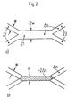
- Zur Herstellung des zweimodigen Wellenleiters werden zwei Möglichkeiten angegeben, die in Fig. 2 schematisch dargestellt sind:
-
- a) Der Wellenleiter 21 besitzt die gleiche maximale Brechzahlerhöhung An wie die Wellenleiter 22 und 23, ist jedoch um so viel breiter (~2w), daß er zwei Moden führt, oder b) er besitzt die gleiche Breite w wie die Wellenleiter 22 und 23, weist dafür aber ein größeres Δn (~ 2An) auf, um so die Führung der zwei Moden zu gewährleisten. Die erstgenannte Struktur ist als BOA-Koppler bekannt (M. Papuchon und A. Roy: Appl. Phys. Lett., 31 (1977), Seiten 266 - 267), während die zweite auf dem Prinzip der Wellenleiterkreuzung mit doppeltem Δn im Überschneidungsbereich (siehe oben genannte Arbeit von A. Neyer) aufbaut.
- Die einfache Herstellung des Wellenlängenmultiplexers /-demultiplexers in den unterschiedlichsten Materialien (z.B. Glas, LiNb03, GaAs etc.) erlaubt die Realisierung zahlreicher neuartiger Ausbildungen der Erfindung, die in den Ansprüchen 1 - 9 beschrieben sind und in den Ausführungsbeispielen der Erfindung näher erläutert werden. Ausführungsbeispiele der Erfindung sind in den Zeichnungen dargestellt und werden im folgenden näher beschrieben:
- Fig. 1 zeigt den integriert-optischen Wellenlängenmultiplexer / -demultiplexer mit einem zweimodigen Streifenwellenleiter und vier angeschlossenen Monomode-Streifenwellenleitern,
- Fig. 2 zeigt zwei Ausführungsbeispiele der Erfindung, wobei der zweimodige Streifenwellenleiter
- a) eine nahezu doppelt so große Breite bzw.
- b) eine nahezu doppelt so große maximale Brechzahlerhöhung wie die der Monomode-Streifenwellenleiter besitzt,
- Fig. 3 zeigt einen Wellenlängenmultiplexer /-demultiplexer mit zusätzlich eingeprägtem Brechzahlstreifen.
- a) Aufsicht
- b) Schnitt A-A',
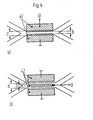
- Fig. 4 zeigt Elektrodenkonfigurationen, mit denen der angegebene Wellenlängenmultiplexer /-demultiplexer elektrooptisch abgestimmt werden kann, und zwar auf elektrooptischen Substraten, bei denen
- a) das elektrische Feld parallel zur Substratoberfläche,
- b) das elektrische Feld senkrecht zur Substratoberfläche ausgenutzt wird,
- Fig. 5 zeigt einen thermooptisch abstimmbaren Wellenlängenmultiplexer/ -demultiplexer,
- Fig. 6 zeigt die Anwendung des Wellenlängenmultiplexers /-demultiplexers für eine Vielkanal-WDM Einrichtung in kaskadierter Anordnung, und zwar
- a) den schematsichen Aufbau,
- b) das Funktionsprinzip.
- Fig. 4a zeigt einen Wellenlängenmultiplexer /-demultiplexer in einem elektrooptischen Material, dessen größter elektrooptischer Koeffizient durch elektrische Felder parallel zur Substratoberfläche ausgenutzt wird, wie das z.B. in Y- bzw. X-geschnittenen LiNb03- und LiTa03-Kristallen der Fall ist.
- Die zwei Koplanar-Elektroden 41 besitzen einen Abstand b, der kleiner als die Wellenleiterbreite d ist. Mit einer an diese Elektroden angelegten Spannung wird die Brechzahl des Wellenleiters im Bereich zwischen den Elektroden aufgrund des elektrooptischen Effektes geändert. Dadurch ergibt sich eine spannungsabhängige differentielle Änderung der Modendispersion γ(U), die sich gemäß Gleichung (4) auf Ax auswirkt. Auf diese Weise lassen sich mit Hilfe eines angelegten elektrischen Feldes z.B. Schwankungen in der Laserwellenlänge oder fabrikationsbedingte Toleranzen bei der Wellenleiterherstellung elektrooptisch ausgleichen.
- Fig. 4b zeigt einen Wellenlängenmultiplexer /-demultiplexer in einem elektrooptischen Material, dessen größter elektrooptischer Koeffizient mit Hilfe von elektrischen Feldern senkrecht zur Substratoberfläche ausgenutzt wird, wie das z.B. in Z-geschnittenen LiNb03- und LiTa03-Kristallen der Fall ist. Die Breite b der Mittelelektrode der Dreielektrodenstruktur42 ist kleiner als die Wellenleiterbreite d. Mit einer an diese Elektrodenanordnung angelegten Spannung U wird die Brechzahl des Wellenleiters insbesondere unter der Mittelelektrode aufgrund des elektrooptischen Effektes verändert.
- Fig. 5 zeigt einen Wellenlängenmultiplexer /-demultiplexer in einem Material, das den thermooptischen Effekt zeigt, wie z.B. Glas (M. Haruna und J. Koyoma: Appl. Opt., 21 (1982), Seiten 3461 - 3465). Das auf den Wellenleiter 51 aufgebrachte Nickel-Chrom Heizelement 52 besitzt die Breite b, die kleiner als die Wellenleiterbreite d ist. Der durch das Heizelement 52 geführte Strom I bewirkt aufgrund des thermooptischen Effektes eine Brechzahländerung im Wellenleiter, die direkt unter dem Heizelement maximal ist. Daraus resultiert eine stromabhängige Änderung der differentiellen Modendispersion: γ = γ(I).
- Fig. 6a zeigt den schematischen Aufbau eines 4-Kanal-Wellenlängenmultiplexers /-demultiplexers. Dazu werden zwei identische erfindungsgemäße 2-Kanal-Wellenlängenmultiplexer (I, II) parallel geschaltet, deren Ausgänge 4' und 3" wiederum als Eingänge des dritten Multiplexers (III) dienen. Der Multiplexer III unterscheidet sich von den Multiplexern I und II dadurch, daß er die doppelte Länge 2L des zweimodigen Multiplexerwellenleiters aufweist.
- Fig. 6b zeigt das Funktionsprinzip des 4-Kanal-Wellenlängenmultiplexersl -demultiplexers. Aufgrund identischer Dimensionierung besitzen die beiden Multiplexer I und II ein identisch Δλ¶. Sind nun die Wellenlängen λ1 und λ2 so gewählt, daß ihre Differenz gerade Δλ¶ entspricht, dann erscheinen beide Wellenlängen gemäß Gleichungen (3) und (4) am Ausgang 4' des Multiplexers I.
- Für die Wellenlänge λ3 und λ4 gilt, daß sie am selben Ausgang des Multiplexers II erscheinen, falls auch deren Differenz gerade △λπ entspricht. Die Transmissionscharakteristik des-Multiplexers wird im hier betrachteten Fall elektrooptisch so eingestellt, daß alles Licht der Wellenlängen λ3 und λ4 in den Ausgangsarm 3" ausgekoppelt wird. Da nun der Multiplexer III eine doppelt so große Länge (2L) wie die der Multiplexer I und II (L) aufweist, ist gemäß Gleichungen (3) und (4) seine Periodizität in x auch doppelt so groß. Das bedeutet, daß zwei Lichtwellenlängen mit der Wellenlängendifferenz △λπ , die entweder im Eingangsarm 4' oder 3" eingekoppelt werden, am selben Ausgangsarm des Multiplexers III erscheinen. Sind die Wellenlängen λ1 bis λ4 nun so gestaffelt, daß die Differenzen λ1 - λ3 = λ4 - λ1 x2 - λ4 = △λπ/2 sind, dann werden all diese Wellenlängen gemeinsam in einen der beiden Ausgänge 4"' oder 3"' ausgekoppelt. Der gewünschte Ausgangskanal kann elektrooptisch angewählt werden.
- Durch eine Kaskadierung mehrerer in Fig. 6a gezeigter Strukturen können N-Kanal Multiplexer / Demultiplexer aufgebaut werden. Dazu werden die N = 2n (n = 1,2,3 etc.) Wellenlängen mit Hilfe von n hintereinandergeschalteten erfindungsgemäßen Multiplexer-/Demultiplexerstufen nahezu verlustlos in einen Wellenleiter zusammengeführt bzw. wellenlängenselektiv auf N Wellenleiter verteilt. Die Anzahl der parallel geschalteten Multiplexer / Demultiplexer in einer Stufe geht dabei von 2n-1 in der ersten bzw. letzten Stufe auf einen einzigen Multiplexer in der letzten bzw. ersten Stufe zurück. Die Länge der lateral zweimodigen Multiplexer-/Demultiplexer-Streifenwellenleiter steigt dagegen von L in der ersten bzw. letzten Stufe auf 2n-1 .L in der letzten bzw. ersten Stufe an. Durch eine solche Kaskadierung lassen sich insbesondere sehr verlustarme und kompakte N-Kanal Wellenlängenmultiplexer herstellen.
Claims (9)
Applications Claiming Priority (2)
| Application Number | Priority Date | Filing Date | Title |
|---|---|---|---|
| DE3406207 | 1984-02-21 | ||
| DE19843406207 DE3406207A1 (de) | 1984-02-21 | 1984-02-21 | Integriert-optische wellenlaengenmultiplex- und -demultiplexeinrichtung fuer monomode-uebertragungssysteme und ihre verwendung |
Publications (2)
| Publication Number | Publication Date |
|---|---|
| EP0152991A2 true EP0152991A2 (de) | 1985-08-28 |
| EP0152991A3 EP0152991A3 (de) | 1988-01-07 |
Family
ID=6228369
Family Applications (1)
| Application Number | Title | Priority Date | Filing Date |
|---|---|---|---|
| EP85200218A Withdrawn EP0152991A3 (de) | 1984-02-21 | 1985-02-20 | Integriert-optische Wellenlängenmultiplex- und -demultiplexeinrichtung für Monomode-Übertragungssysteme und ihre Verwendung |
Country Status (4)
| Country | Link |
|---|---|
| US (1) | US4690489A (de) |
| EP (1) | EP0152991A3 (de) |
| JP (1) | JPS60232511A (de) |
| DE (1) | DE3406207A1 (de) |
Cited By (7)
| Publication number | Priority date | Publication date | Assignee | Title |
|---|---|---|---|---|
| EP0183449A3 (de) * | 1984-11-21 | 1988-01-13 | THE GENERAL ELECTRIC COMPANY, p.l.c. | Optische Verbindungen |
| EP0306956A3 (en) * | 1987-09-11 | 1989-12-27 | Hitachi, Ltd. | Waveguide type optical multiplexer/demultiplexer |
| US4952015A (en) * | 1988-04-12 | 1990-08-28 | U.S. Philips Corp. | Radiation coupling device |
| EP0408261A1 (de) * | 1989-07-11 | 1991-01-16 | THE GENERAL ELECTRIC COMPANY, p.l.c. | Integrierter optischer Wellenleiter-Koppler |
| US5010587A (en) * | 1988-03-11 | 1991-04-23 | Telefonaktiebolaget L M Ericsson | Appartaus for transmitting a coherent frequency modulated optical signal |
| EP0528431A1 (de) * | 1991-08-20 | 1993-02-24 | Hewlett-Packard Company | Integriert-optischer Baustein für Monomode-Betrieb in einem breiten Wellenlängenbereich |
| EP0472382B1 (de) * | 1990-08-22 | 1996-10-30 | Gec-Marconi Limited | Integriert optischer Wellenleiterkoppler |
Families Citing this family (19)
| Publication number | Priority date | Publication date | Assignee | Title |
|---|---|---|---|---|
| US4860279A (en) * | 1988-11-30 | 1989-08-22 | The Boeing Company | Source modulated coherence multiplexed optical signal transmission system |
| US4906064A (en) * | 1988-12-30 | 1990-03-06 | Bell Communications Research, Inc. | Switch for selectively switching optical wavelengths |
| DE3904752A1 (de) * | 1989-02-16 | 1990-08-23 | Siemens Ag | Vorrichtung fuer den optischen direktempfang mehrerer wellenlaengen |
| US4997245A (en) * | 1990-01-04 | 1991-03-05 | Smiths Industries Aerospace & Defense Systems Incorporated | Polarization independent optical switches |
| US5044712A (en) * | 1990-06-29 | 1991-09-03 | The United States Of America As Represented By The Secretary Of The Air Force | Waveguided electrooptic switches using ferroelectric liquid crystals |
| EP0466082B1 (de) * | 1990-07-09 | 1997-05-02 | Canon Kabushiki Kaisha | Verfahren zur Lichtmodulation und optischer Modulator |
| USRE35516E (en) * | 1990-07-27 | 1997-05-20 | Lucent Technologies Inc. | Adiabatic reflection Y-coupler apparatus |
| US5048909A (en) * | 1990-07-27 | 1991-09-17 | At&T Bell Laboratories | Adiabatic reflection apparatus |
| US5093876A (en) * | 1990-07-27 | 1992-03-03 | At&T Bell Laboratories | WDM systems incorporating adiabatic reflection filters |
| EP0480872B1 (de) * | 1990-10-10 | 1994-11-09 | SULZER Medizinaltechnik AG | Femurkopfprothese |
| JP2773990B2 (ja) * | 1991-04-15 | 1998-07-09 | 日本碍子株式会社 | 光導波路基板と光ファイバ整列用基板との結合体の製造方法 |
| NL9101532A (nl) * | 1991-09-10 | 1993-04-01 | Nederland Ptt | Golflengte-selectieve multiplexer en demultiplexer. |
| US5355237A (en) * | 1993-03-17 | 1994-10-11 | The United States Of America As Represented By The Administrator Of The National Aeronautics And Space Administration | Wavelength-division multiplexed optical integrated circuit with vertical diffraction grating |
| US5600479A (en) * | 1995-12-22 | 1997-02-04 | Corning Incorporated | Method and apparatus for optical logic and switching functions |
| US6201914B1 (en) * | 1997-04-15 | 2001-03-13 | UNIVERSITé LAVAL | Tapered waveguide for optical dispersion compensation |
| US6400855B1 (en) | 1999-04-16 | 2002-06-04 | Radiant Photonics, Inc. | N × N optical switching array device and system |
| KR20040009525A (ko) * | 2002-07-24 | 2004-01-31 | 영 철 정 | 미세 채널 조정이 가능한 저밀도 파장 분할 다중화용두모드 간섭 파장 다중화기 |
| EP1426799A3 (de) * | 2002-11-29 | 2005-05-18 | Matsushita Electric Industrial Co., Ltd. | Optischer Demultiplexer, optischer Multiplexer/Demultiplexer, und optische Vorrichtung |
| NL1025226C2 (nl) * | 2003-05-22 | 2004-12-14 | Lionix B V | Inrichting, samenstel en werkwijzen voor het golflengteafhankelijk bewerken van optische signalen. |
Family Cites Families (3)
| Publication number | Priority date | Publication date | Assignee | Title |
|---|---|---|---|---|
| FR2379086A1 (fr) * | 1977-01-31 | 1978-08-25 | Thomson Csf | Dispositif optique de transmission guidee a commande electrique |
| US4390236A (en) * | 1981-03-19 | 1983-06-28 | Bell Telephone Laboratories, Incorporated | Tunable polarization independent wavelength filter |
| DE3322508A1 (de) * | 1983-06-23 | 1985-01-17 | Standard Elektrik Lorenz Ag, 7000 Stuttgart | Optisch einmodige streifenwellenleiterkreuzung |
-
1984
- 1984-02-21 DE DE19843406207 patent/DE3406207A1/de not_active Withdrawn
-
1985
- 1985-02-19 US US06/702,523 patent/US4690489A/en not_active Expired - Fee Related
- 1985-02-20 EP EP85200218A patent/EP0152991A3/de not_active Withdrawn
- 1985-02-21 JP JP60031641A patent/JPS60232511A/ja active Pending
Cited By (8)
| Publication number | Priority date | Publication date | Assignee | Title |
|---|---|---|---|---|
| EP0183449A3 (de) * | 1984-11-21 | 1988-01-13 | THE GENERAL ELECTRIC COMPANY, p.l.c. | Optische Verbindungen |
| EP0306956A3 (en) * | 1987-09-11 | 1989-12-27 | Hitachi, Ltd. | Waveguide type optical multiplexer/demultiplexer |
| US4970713A (en) * | 1987-09-11 | 1990-11-13 | Hitachi, Ltd. | Waveguide type optical multiplexer/demultiplexer with a wave guide regulating function |
| US5010587A (en) * | 1988-03-11 | 1991-04-23 | Telefonaktiebolaget L M Ericsson | Appartaus for transmitting a coherent frequency modulated optical signal |
| US4952015A (en) * | 1988-04-12 | 1990-08-28 | U.S. Philips Corp. | Radiation coupling device |
| EP0408261A1 (de) * | 1989-07-11 | 1991-01-16 | THE GENERAL ELECTRIC COMPANY, p.l.c. | Integrierter optischer Wellenleiter-Koppler |
| EP0472382B1 (de) * | 1990-08-22 | 1996-10-30 | Gec-Marconi Limited | Integriert optischer Wellenleiterkoppler |
| EP0528431A1 (de) * | 1991-08-20 | 1993-02-24 | Hewlett-Packard Company | Integriert-optischer Baustein für Monomode-Betrieb in einem breiten Wellenlängenbereich |
Also Published As
| Publication number | Publication date |
|---|---|
| DE3406207A1 (de) | 1985-08-29 |
| US4690489A (en) | 1987-09-01 |
| EP0152991A3 (de) | 1988-01-07 |
| JPS60232511A (ja) | 1985-11-19 |
Similar Documents
| Publication | Publication Date | Title |
|---|---|---|
| EP0152991A2 (de) | Integriert-optische Wellenlängenmultiplex- und -demultiplexeinrichtung für Monomode-Übertragungssysteme und ihre Verwendung | |
| DE60314829T2 (de) | Optischer Multiplex/Demultiplex-Schaltkreis mit einem Phasengenerator | |
| CA1115402A (en) | Tunable optical waveguide directional coupler filter | |
| DE3209927C2 (de) | ||
| DE69018660T2 (de) | Optische Verzweigungskomponenten und Schalter mit geführten Wellen. | |
| DE19509447C2 (de) | Optischer Wellenleiter-Multiplexer/Demultiplexer und zugehöriges Verfahren | |
| DE69731500T2 (de) | Akustooptische Wellenleitervorrichtung mit Kompensation der Polarisationsmodendispersion | |
| DE68918764T2 (de) | Wellenlängenmultiplexermodul. | |
| DE60010053T2 (de) | Elektrisch verstellbares beugungsgitter | |
| DE60314210T2 (de) | Durchstimmbarer Dispersionskompensator mit Wenigmodenfasern und mit schaltbaren Modenkonvertern | |
| DE69023028T2 (de) | Bauelement für die adiabatische Veränderung der Polarisation. | |
| DE102009021043A1 (de) | Planare Lichtwellenschaltung und abstimmbare Laservorrichtung, die diese aufweist | |
| DE60309783T2 (de) | Abstimmungsmethode für optischen Schaltkreis mit kaskadierten Mach-Zehnder-Interferometern | |
| DE69116014T2 (de) | Optischer Wellenleiterschalter für zwei Wellenlängen | |
| DE2804105A1 (de) | Elektrisch steuerbare optische uebertragungsvorrichtung | |
| EP0740173A2 (de) | Schaltungsanordnung zur Dispersionskompensation in optischen Übertragungssystemen mittels eines optischen Filters | |
| DE60121593T2 (de) | Durch bragg-gitter unterstützter mmimi-koppler für das abstimmbare add/drop-multiplexen | |
| DE69730384T2 (de) | Optisches Bauelement | |
| DE60038034T2 (de) | Verfahren und vorrichtung für optisches multiplexen/demultiplexen | |
| DE4240548A1 (de) | ||
| DE60222918T2 (de) | Verfahren und vorrichtung zum schalten und modulieren eines optischen signals mit erhöhter empfindlichkeit | |
| US6510266B2 (en) | Tunable optoelectronic frequency filter | |
| DE60114387T2 (de) | Einrichtung und verfahren zum optischen add/drop-multiplexen | |
| DE69205103T2 (de) | Integriert-optischer Baustein für Monomode-Betrieb in einem breiten Wellenlängenbereich. | |
| EP0215804B1 (de) | Muldex für optische übertragungssysteme |
Legal Events
| Date | Code | Title | Description |
|---|---|---|---|
| PUAI | Public reference made under article 153(3) epc to a published international application that has entered the european phase |
Free format text: ORIGINAL CODE: 0009012 |
|
| AK | Designated contracting states |
Designated state(s): DE FR GB IT NL SE |
|
| RAP1 | Party data changed (applicant data changed or rights of an application transferred) |
Owner name: N.V. PHILIPS' GLOEILAMPENFABRIEKEN Owner name: PHILIPS PATENTVERWALTUNG GMBH |
|
| PUAL | Search report despatched |
Free format text: ORIGINAL CODE: 0009013 |
|
| RHK1 | Main classification (correction) |
Ipc: G02B 6/34 |
|
| AK | Designated contracting states |
Kind code of ref document: A3 Designated state(s): DE FR GB IT NL SE |
|
| 17P | Request for examination filed |
Effective date: 19880617 |
|
| 17Q | First examination report despatched |
Effective date: 19910222 |
|
| STAA | Information on the status of an ep patent application or granted ep patent |
Free format text: STATUS: THE APPLICATION HAS BEEN WITHDRAWN |
|
| 18W | Application withdrawn |
Withdrawal date: 19910524 |
|
| R18W | Application withdrawn (corrected) |
Effective date: 19910524 |
|
| RIN1 | Information on inventor provided before grant (corrected) |
Inventor name: NEYER, ANDREAS |