EP0152991A2 - Multiplexeur/démultiplexeur de longueur d'onde optiquement intégré pour un système monomode de communication et sa mise en oeuvre - Google Patents
Multiplexeur/démultiplexeur de longueur d'onde optiquement intégré pour un système monomode de communication et sa mise en oeuvre Download PDFInfo
- Publication number
- EP0152991A2 EP0152991A2 EP85200218A EP85200218A EP0152991A2 EP 0152991 A2 EP0152991 A2 EP 0152991A2 EP 85200218 A EP85200218 A EP 85200218A EP 85200218 A EP85200218 A EP 85200218A EP 0152991 A2 EP0152991 A2 EP 0152991A2
- Authority
- EP
- European Patent Office
- Prior art keywords
- mode
- wavelength
- strip
- waveguide
- demultiplexing device
- Prior art date
- Legal status (The legal status is an assumption and is not a legal conclusion. Google has not performed a legal analysis and makes no representation as to the accuracy of the status listed.)
- Withdrawn
Links
Images


Classifications
-
- G—PHYSICS
- G02—OPTICS
- G02B—OPTICAL ELEMENTS, SYSTEMS OR APPARATUS
- G02B6/00—Light guides; Structural details of arrangements comprising light guides and other optical elements, e.g. couplings
- G02B6/10—Light guides; Structural details of arrangements comprising light guides and other optical elements, e.g. couplings of the optical waveguide type
- G02B6/12—Light guides; Structural details of arrangements comprising light guides and other optical elements, e.g. couplings of the optical waveguide type of the integrated circuit kind
- G02B6/122—Basic optical elements, e.g. light-guiding paths
- G02B6/125—Bends, branchings or intersections
-
- G—PHYSICS
- G02—OPTICS
- G02B—OPTICAL ELEMENTS, SYSTEMS OR APPARATUS
- G02B6/00—Light guides; Structural details of arrangements comprising light guides and other optical elements, e.g. couplings
- G02B6/10—Light guides; Structural details of arrangements comprising light guides and other optical elements, e.g. couplings of the optical waveguide type
- G02B6/12—Light guides; Structural details of arrangements comprising light guides and other optical elements, e.g. couplings of the optical waveguide type of the integrated circuit kind
- G02B6/12007—Light guides; Structural details of arrangements comprising light guides and other optical elements, e.g. couplings of the optical waveguide type of the integrated circuit kind forming wavelength selective elements, e.g. multiplexer, demultiplexer
-
- G—PHYSICS
- G02—OPTICS
- G02F—OPTICAL DEVICES OR ARRANGEMENTS FOR THE CONTROL OF LIGHT BY MODIFICATION OF THE OPTICAL PROPERTIES OF THE MEDIA OF THE ELEMENTS INVOLVED THEREIN; NON-LINEAR OPTICS; FREQUENCY-CHANGING OF LIGHT; OPTICAL LOGIC ELEMENTS; OPTICAL ANALOGUE/DIGITAL CONVERTERS
- G02F1/00—Devices or arrangements for the control of the intensity, colour, phase, polarisation or direction of light arriving from an independent light source, e.g. switching, gating or modulating; Non-linear optics
- G02F1/29—Devices or arrangements for the control of the intensity, colour, phase, polarisation or direction of light arriving from an independent light source, e.g. switching, gating or modulating; Non-linear optics for the control of the position or the direction of light beams, i.e. deflection
- G02F1/31—Digital deflection, i.e. optical switching
- G02F1/313—Digital deflection, i.e. optical switching in an optical waveguide structure
- G02F1/3137—Digital deflection, i.e. optical switching in an optical waveguide structure with intersecting or branching waveguides, e.g. X-switches and Y-junctions
-
- G—PHYSICS
- G02—OPTICS
- G02B—OPTICAL ELEMENTS, SYSTEMS OR APPARATUS
- G02B6/00—Light guides; Structural details of arrangements comprising light guides and other optical elements, e.g. couplings
- G02B6/24—Coupling light guides
- G02B6/26—Optical coupling means
- G02B6/28—Optical coupling means having data bus means, i.e. plural waveguides interconnected and providing an inherently bidirectional system by mixing and splitting signals
- G02B6/2804—Optical coupling means having data bus means, i.e. plural waveguides interconnected and providing an inherently bidirectional system by mixing and splitting signals forming multipart couplers without wavelength selective elements, e.g. "T" couplers, star couplers
- G02B6/2808—Optical coupling means having data bus means, i.e. plural waveguides interconnected and providing an inherently bidirectional system by mixing and splitting signals forming multipart couplers without wavelength selective elements, e.g. "T" couplers, star couplers using a mixing element which evenly distributes an input signal over a number of outputs
- G02B6/2813—Optical coupling means having data bus means, i.e. plural waveguides interconnected and providing an inherently bidirectional system by mixing and splitting signals forming multipart couplers without wavelength selective elements, e.g. "T" couplers, star couplers using a mixing element which evenly distributes an input signal over a number of outputs based on multimode interference effect, i.e. self-imaging
-
- G—PHYSICS
- G02—OPTICS
- G02F—OPTICAL DEVICES OR ARRANGEMENTS FOR THE CONTROL OF LIGHT BY MODIFICATION OF THE OPTICAL PROPERTIES OF THE MEDIA OF THE ELEMENTS INVOLVED THEREIN; NON-LINEAR OPTICS; FREQUENCY-CHANGING OF LIGHT; OPTICAL LOGIC ELEMENTS; OPTICAL ANALOGUE/DIGITAL CONVERTERS
- G02F1/00—Devices or arrangements for the control of the intensity, colour, phase, polarisation or direction of light arriving from an independent light source, e.g. switching, gating or modulating; Non-linear optics
- G02F1/01—Devices or arrangements for the control of the intensity, colour, phase, polarisation or direction of light arriving from an independent light source, e.g. switching, gating or modulating; Non-linear optics for the control of the intensity, phase, polarisation or colour
- G02F1/0147—Devices or arrangements for the control of the intensity, colour, phase, polarisation or direction of light arriving from an independent light source, e.g. switching, gating or modulating; Non-linear optics for the control of the intensity, phase, polarisation or colour based on thermo-optic effects
Definitions
- the invention relates to an integrated optical wavelength multiplexer and demultiplexer for optically single-mode glass fiber transmission systems and its use.
- WDM wavelength division multiplexing
- WDM methods have so far mainly been used which are based on micro-optical components (T. Uchida and Sugimoto: 4th European Conference on Optical Communication, Geneva 1978, contribution 8-1, G. Winzer et al .: Appl. Opt ., 20 (1981), pages 3128 - 3135, M. Seki et al .: Electron. Lett., 18 (1982), pages 257 - 258) and with fiber optic components (M. Digonnet and HJ Shaw: Appl. Opt. , 22 (1983), pages 484-491, SK Sheem and RP Moeller: J. Appl. Phys., 51 (1980), pages 4050-4052). All of these processes require a relatively large outlay for the production and installation of the wavelength-selective elements and for the adjustment of the individual monomode fibers.
- WDM devices have been investigated for some time, in which the use of components of the integrated optics is provided.
- the integrated optics allow the production of many wavelength-selective components with the necessary monomode strip waveguides on a substrate and also includes the manufacturing advantages of planar technology.
- the disadvantages of the cited directional coupler solution lie on the one hand in the non-identical strip waveguides, which lead to different coupling efficiencies when coupling to glass fibers or subsequent cascaded directional couplers, and on the other hand in the need to dimension the individual directional couplers differently in the case of a multi-channel WDM .
- the large overall length of the directional coupler ( ⁇ 1 cm) and the low crosstalk attenuation achieved (- 17 dB) speak against the cascading of several directional couplers for use in multi-channel WDM.
- the TE-TM converter has a shorter overall length (6 mm) and better crosstalk attenuation (20 dB), it has the major disadvantage that it consists of only one strip waveguide and therefore neither a spatial merging nor a spatial separation of the spectral disassembled signals allowed. It is therefore not suitable for multi-channel WDM use or only to a limited extent on the demultiplexer side.
- the invention has for its object to provide an integrated-optical wavelength multiplexer / demultiplexer for monomode transmission systems, which can be used as a passive and electrically controllable component for multi-channel WDM and does not have the disadvantages mentioned in the prior art.
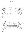
- the integrated optical wavelength multiplexer / demultiplexer consists of a laterally two-mode strip waveguide to which two single-mode strip waveguides are connected on each side.
- the structure of the WDM device according to the invention is shown in FIG. 1.
- the core of this component is the laterally two-mode Strip waveguide 11, whose wavelength-dependent mode dispersion is used for wavelength selection.
- the almost lossless coupling of the single-mode strip waveguides 12 and 13 to the two-mode strip waveguide takes place with the aid of tapered directional couplers, the mode of operation of which is described, for example, in the work A. Neyer: Electron. Lett., 19 (1983), pages 553-554.
- the principle of operation of the wavelength multiplexer / demultiplexer specified here is based on the differential mode dispersion of the two-mode waveguide, ie on the different dependence of the phase constants of the fundamental wave ( ⁇ 0 ) and the first lateral fundamental mode ( 81 ) on the wavelength x. This fact has the consequence that after traveling a distance L of the waveguide 11 both waves have a relative phase difference ⁇ which depends on the wavelength x in the following way
- This wavelength-periodic property distinguishes the multiplexer / demultiplexer specified here from the asymmetrical directional coupler and TE-TM converter solution. It offers the advantage detailed below that a multi-channel multiplexer can be created in the form of a tree structure.
- the wavelength difference ⁇ ⁇ at which the output light powers are completely interchanged, can be achieved on the one hand by changing the length L, and on the other hand by modifying the differential mode dispersion y. Such a modification is particularly effective if a stripe-shaped change in the refractive index is carried out in the region of the two-mode waveguide, as shown in FIG. 3.
- This refractive index strip (32) whose width b is smaller than the width d of the strip waveguide (31), runs parallel and symmetrically to the axis B-B '.
- the mode dispersion of the symmetrical mode is influenced much more than that of the antisymmetric mode, since this has a zero crossing of the field distribution in the region of the line of symmetry BB '.
- both a change in the A ⁇ and a change in the differential mode dispersion y are achieved.
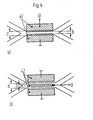
- the refractive index strip described can now be produced statically (for example by ion implantation, ion exchange etc.) or it can also be induced by physical effects such as the electro-optical effect. This results in the possibility of, for example, electrically tuning the wavelength division multiplexer / demultiplexer to a predetermined wavelength difference ⁇ . Using the principle described in patent application P 3322508.7, it is also possible to change the ⁇ (see Eq. 1) and thus to control the light distribution ratio P 3 / P 4, for example electrically.
- the two coplanar electrodes 41 have a distance b that is smaller than the waveguide width d.
- the refractive index of the waveguide in the area between the electrodes is changed due to the electro-optical effect.
- an applied electric field e.g. Compensate for fluctuations in the laser wavelength or manufacturing-related tolerances in the waveguide manufacture electro-optically.
- FIG. 4b shows a wavelength division multiplexer / demultiplexer in an electro-optical material, the largest electro-optical coefficient of which with the aid of electrical fields perpendicular to the The substrate surface is used, as is the case, for example, in Z-cut LiNb0 3 and LiTa0 3 crystals.
- the width b of the center electrode of the three-electrode structure 42 is smaller than the waveguide width d. With a voltage U applied to this electrode arrangement, the refractive index of the waveguide is changed, in particular under the center electrode, on account of the electro-optical effect.
- Fig. 5 shows a wavelength division multiplexer / demultiplexer in a material which shows the thermo-optical effect, such as glass (M. Haruna and J. Koyoma: Appl. Opt., 21 (1982), pages 3461-3465).
- FIG. 6a shows the schematic structure of a 4-channel wavelength multiplexer / demultiplexer.
- two identical 2-channel wavelength multiplexers (I, II) according to the invention are connected in parallel, the outputs 4 'and 3 "of which in turn serve as inputs of the third multiplexer (III).
- the multiplexer III differs from the multiplexers I and II in that it has twice the length 2L of the two-mode multiplexer waveguide.
- 6b shows the principle of operation of the 4-channel wavelength division multiplexer / demultiplexer. Due to identical dimensions, the two multiplexers I and II have an identical ⁇ ⁇ . If the wavelengths ⁇ 1 and ⁇ 2 are now selected so that their difference corresponds exactly to ⁇ ⁇ , then both wavelengths appear at the output 4 'of the multiplexer I according to equations (3) and (4).
- the multiplexer III is now twice as long (2L) as that of the multiplexer I and II (L), according to equations (3) and (4), its periodicity in x is also twice as large. This means that two light wavelengths with the wavelength difference ⁇ ⁇ , which are coupled in either the input arm 4 'or 3 ", appear on the same output arm of multiplexer III.
- the desired output channel can be selected electro-optically.
- N-channel multiplexers / demultiplexers can be constructed by cascading several structures shown in FIG. 6a.
- the number of multiplexers / demultiplexers connected in parallel in one stage decreases from 2 n-1 in the first or last stage to a single multiplexer in the last or first stage.
- the length of the laterally two-mode multiplexer / demultiplexer strip waveguide increases from L in the first and last stage to 2 n-1 .L in the last and first stage.
- Such cascading makes it possible, in particular, to produce very low-loss and compact N-channel wavelength division multiplexers.
Landscapes
- Physics & Mathematics (AREA)
- General Physics & Mathematics (AREA)
- Optics & Photonics (AREA)
- Engineering & Computer Science (AREA)
- Microelectronics & Electronic Packaging (AREA)
- Nonlinear Science (AREA)
- Optical Integrated Circuits (AREA)
- Optical Communication System (AREA)
Applications Claiming Priority (2)
| Application Number | Priority Date | Filing Date | Title |
|---|---|---|---|
| DE19843406207 DE3406207A1 (de) | 1984-02-21 | 1984-02-21 | Integriert-optische wellenlaengenmultiplex- und -demultiplexeinrichtung fuer monomode-uebertragungssysteme und ihre verwendung |
| DE3406207 | 1984-02-21 |
Publications (2)
| Publication Number | Publication Date |
|---|---|
| EP0152991A2 true EP0152991A2 (fr) | 1985-08-28 |
| EP0152991A3 EP0152991A3 (fr) | 1988-01-07 |
Family
ID=6228369
Family Applications (1)
| Application Number | Title | Priority Date | Filing Date |
|---|---|---|---|
| EP85200218A Withdrawn EP0152991A3 (fr) | 1984-02-21 | 1985-02-20 | Multiplexeur/démultiplexeur de longueur d'onde optiquement intégré pour un système monomode de communication et sa mise en oeuvre |
Country Status (4)
| Country | Link |
|---|---|
| US (1) | US4690489A (fr) |
| EP (1) | EP0152991A3 (fr) |
| JP (1) | JPS60232511A (fr) |
| DE (1) | DE3406207A1 (fr) |
Cited By (7)
| Publication number | Priority date | Publication date | Assignee | Title |
|---|---|---|---|---|
| EP0183449A2 (fr) * | 1984-11-21 | 1986-06-04 | THE GENERAL ELECTRIC COMPANY, p.l.c. | Coupleurs optiques |
| EP0306956A2 (fr) * | 1987-09-11 | 1989-03-15 | Hitachi, Ltd. | Multiplexeur/démultiplexeur optique à guide d'ondes |
| US4952015A (en) * | 1988-04-12 | 1990-08-28 | U.S. Philips Corp. | Radiation coupling device |
| EP0408261A1 (fr) * | 1989-07-11 | 1991-01-16 | THE GENERAL ELECTRIC COMPANY, p.l.c. | Coupleur de guides d'ondes optiques intégré |
| US5010587A (en) * | 1988-03-11 | 1991-04-23 | Telefonaktiebolaget L M Ericsson | Appartaus for transmitting a coherent frequency modulated optical signal |
| EP0528431A1 (fr) * | 1991-08-20 | 1993-02-24 | Hewlett-Packard Company | Dispositif d'optique intégrée monomode conçu pour une gamme d'onde étendue |
| EP0472382B1 (fr) * | 1990-08-22 | 1996-10-30 | Gec-Marconi Limited | Coupleur optique intégré de guides d'ondes |
Families Citing this family (19)
| Publication number | Priority date | Publication date | Assignee | Title |
|---|---|---|---|---|
| US4860279A (en) * | 1988-11-30 | 1989-08-22 | The Boeing Company | Source modulated coherence multiplexed optical signal transmission system |
| US4906064A (en) * | 1988-12-30 | 1990-03-06 | Bell Communications Research, Inc. | Switch for selectively switching optical wavelengths |
| DE3904752A1 (de) * | 1989-02-16 | 1990-08-23 | Siemens Ag | Vorrichtung fuer den optischen direktempfang mehrerer wellenlaengen |
| US4997245A (en) * | 1990-01-04 | 1991-03-05 | Smiths Industries Aerospace & Defense Systems Incorporated | Polarization independent optical switches |
| US5044712A (en) * | 1990-06-29 | 1991-09-03 | The United States Of America As Represented By The Secretary Of The Air Force | Waveguided electrooptic switches using ferroelectric liquid crystals |
| EP0466082B1 (fr) * | 1990-07-09 | 1997-05-02 | Canon Kabushiki Kaisha | Procédé pour la modulation de la lumière et modulateur optique |
| US5093876A (en) * | 1990-07-27 | 1992-03-03 | At&T Bell Laboratories | WDM systems incorporating adiabatic reflection filters |
| US5048909A (en) * | 1990-07-27 | 1991-09-17 | At&T Bell Laboratories | Adiabatic reflection apparatus |
| USRE35516E (en) * | 1990-07-27 | 1997-05-20 | Lucent Technologies Inc. | Adiabatic reflection Y-coupler apparatus |
| ATE113819T1 (de) * | 1990-10-10 | 1994-11-15 | Sulzer Medizinaltechnik Ag | Femurkopfprothese. |
| JP2773990B2 (ja) * | 1991-04-15 | 1998-07-09 | 日本碍子株式会社 | 光導波路基板と光ファイバ整列用基板との結合体の製造方法 |
| NL9101532A (nl) * | 1991-09-10 | 1993-04-01 | Nederland Ptt | Golflengte-selectieve multiplexer en demultiplexer. |
| US5355237A (en) * | 1993-03-17 | 1994-10-11 | The United States Of America As Represented By The Administrator Of The National Aeronautics And Space Administration | Wavelength-division multiplexed optical integrated circuit with vertical diffraction grating |
| US5600479A (en) * | 1995-12-22 | 1997-02-04 | Corning Incorporated | Method and apparatus for optical logic and switching functions |
| US6201914B1 (en) * | 1997-04-15 | 2001-03-13 | UNIVERSITé LAVAL | Tapered waveguide for optical dispersion compensation |
| US6400855B1 (en) | 1999-04-16 | 2002-06-04 | Radiant Photonics, Inc. | N × N optical switching array device and system |
| KR20040009525A (ko) * | 2002-07-24 | 2004-01-31 | 영 철 정 | 미세 채널 조정이 가능한 저밀도 파장 분할 다중화용두모드 간섭 파장 다중화기 |
| EP1426799A3 (fr) * | 2002-11-29 | 2005-05-18 | Matsushita Electric Industrial Co., Ltd. | Démultiplexeur optique, multiplexeur/démultiplexeur optique, et dispositif optique |
| NL1025226C2 (nl) * | 2003-05-22 | 2004-12-14 | Lionix B V | Inrichting, samenstel en werkwijzen voor het golflengteafhankelijk bewerken van optische signalen. |
Citations (3)
| Publication number | Priority date | Publication date | Assignee | Title |
|---|---|---|---|---|
| GB2095419A (en) * | 1981-03-19 | 1982-09-29 | Western Electric Co | Polarization-independent wavelength filter |
| JPS5858524A (ja) * | 1981-10-02 | 1983-04-07 | Ricoh Co Ltd | 光スイツチ |
| DE3322508A1 (de) * | 1983-06-23 | 1985-01-17 | Standard Elektrik Lorenz Ag, 7000 Stuttgart | Optisch einmodige streifenwellenleiterkreuzung |
Family Cites Families (1)
| Publication number | Priority date | Publication date | Assignee | Title |
|---|---|---|---|---|
| FR2379086A1 (fr) * | 1977-01-31 | 1978-08-25 | Thomson Csf | Dispositif optique de transmission guidee a commande electrique |
-
1984
- 1984-02-21 DE DE19843406207 patent/DE3406207A1/de not_active Withdrawn
-
1985
- 1985-02-19 US US06/702,523 patent/US4690489A/en not_active Expired - Fee Related
- 1985-02-20 EP EP85200218A patent/EP0152991A3/fr not_active Withdrawn
- 1985-02-21 JP JP60031641A patent/JPS60232511A/ja active Pending
Patent Citations (3)
| Publication number | Priority date | Publication date | Assignee | Title |
|---|---|---|---|---|
| GB2095419A (en) * | 1981-03-19 | 1982-09-29 | Western Electric Co | Polarization-independent wavelength filter |
| JPS5858524A (ja) * | 1981-10-02 | 1983-04-07 | Ricoh Co Ltd | 光スイツチ |
| DE3322508A1 (de) * | 1983-06-23 | 1985-01-17 | Standard Elektrik Lorenz Ag, 7000 Stuttgart | Optisch einmodige streifenwellenleiterkreuzung |
Non-Patent Citations (4)
| Title |
|---|
| ELECTRONICS LETTERS, Band 19, Nr. 14, 7. Juli 1983, Seiten 553-554, Staines, GB; A. NEYER: "Electro-optic x-switch using single-mode Ti:LiNbO3, channel waveguides" * |
| ELECTRONICS LETTERS, Band 20, Nr. 18, August 1984, Seiten 744-746, Staines, Middlesex, GB; A. NEYER: "Integrated-optical multichannel wavelength multiplexer for monomode systems" * |
| IBM TECHNICAL DISCLOSURE BULLETIN, Band 13, Nr. 8, Januar 1971, Seiten 2413-2415, New York, US; M.L. DAKSS et al.: "Detecting multiplexed picosecond pulses" * |
| PATENT ABSTRACTS OF JAPAN, Band 7, Nr. 146 (P-206)[1291], 25. Juni 1983; & JP-A-58 58 524 (RICOH K.K.) 07-04-1983 * |
Cited By (10)
| Publication number | Priority date | Publication date | Assignee | Title |
|---|---|---|---|---|
| EP0183449A2 (fr) * | 1984-11-21 | 1986-06-04 | THE GENERAL ELECTRIC COMPANY, p.l.c. | Coupleurs optiques |
| EP0183449A3 (fr) * | 1984-11-21 | 1988-01-13 | THE GENERAL ELECTRIC COMPANY, p.l.c. | Coupleurs optiques |
| EP0306956A2 (fr) * | 1987-09-11 | 1989-03-15 | Hitachi, Ltd. | Multiplexeur/démultiplexeur optique à guide d'ondes |
| EP0306956A3 (en) * | 1987-09-11 | 1989-12-27 | Hitachi, Ltd. | Waveguide type optical multiplexer/demultiplexer |
| US4970713A (en) * | 1987-09-11 | 1990-11-13 | Hitachi, Ltd. | Waveguide type optical multiplexer/demultiplexer with a wave guide regulating function |
| US5010587A (en) * | 1988-03-11 | 1991-04-23 | Telefonaktiebolaget L M Ericsson | Appartaus for transmitting a coherent frequency modulated optical signal |
| US4952015A (en) * | 1988-04-12 | 1990-08-28 | U.S. Philips Corp. | Radiation coupling device |
| EP0408261A1 (fr) * | 1989-07-11 | 1991-01-16 | THE GENERAL ELECTRIC COMPANY, p.l.c. | Coupleur de guides d'ondes optiques intégré |
| EP0472382B1 (fr) * | 1990-08-22 | 1996-10-30 | Gec-Marconi Limited | Coupleur optique intégré de guides d'ondes |
| EP0528431A1 (fr) * | 1991-08-20 | 1993-02-24 | Hewlett-Packard Company | Dispositif d'optique intégrée monomode conçu pour une gamme d'onde étendue |
Also Published As
| Publication number | Publication date |
|---|---|
| JPS60232511A (ja) | 1985-11-19 |
| US4690489A (en) | 1987-09-01 |
| EP0152991A3 (fr) | 1988-01-07 |
| DE3406207A1 (de) | 1985-08-29 |
Similar Documents
| Publication | Publication Date | Title |
|---|---|---|
| EP0152991A2 (fr) | Multiplexeur/démultiplexeur de longueur d'onde optiquement intégré pour un système monomode de communication et sa mise en oeuvre | |
| CA1115402A (fr) | Filtre optique directif reglable a guides d'ondes couples | |
| DE60314829T2 (de) | Optischer Multiplex/Demultiplex-Schaltkreis mit einem Phasengenerator | |
| DE3209927C2 (fr) | ||
| DE69731500T2 (de) | Akustooptische Wellenleitervorrichtung mit Kompensation der Polarisationsmodendispersion | |
| DE19509447C2 (de) | Optischer Wellenleiter-Multiplexer/Demultiplexer und zugehöriges Verfahren | |
| DE602004004848T2 (de) | Abstimmbarer Dispersionskompensator | |
| DE69937014T2 (de) | Lichtwellenleiterverzweigung mit Reflektor | |
| DE60010053T2 (de) | Elektrisch verstellbares beugungsgitter | |
| DE60314210T2 (de) | Durchstimmbarer Dispersionskompensator mit Wenigmodenfasern und mit schaltbaren Modenkonvertern | |
| DE60309783T2 (de) | Abstimmungsmethode für optischen Schaltkreis mit kaskadierten Mach-Zehnder-Interferometern | |
| EP0740173B1 (fr) | Structure de circuit pour compenser la dispersion dans les systèmes de télécommunications optiques au moyen d'un filtre optique | |
| DE102009021043A1 (de) | Planare Lichtwellenschaltung und abstimmbare Laservorrichtung, die diese aufweist | |
| DE2804105C2 (fr) | ||
| DE2843763A1 (de) | Elektromagnetischer doppelpolarisations-schalter und/oder -modulator | |
| EP0260594B1 (fr) | Dispositif pour contrôler la polarisation, en particulier dans un récepteur optique homodyne ou hétérodyne | |
| DE69730384T2 (de) | Optisches Bauelement | |
| DE4240548A1 (fr) | ||
| DE60121593T2 (de) | Durch bragg-gitter unterstützter mmimi-koppler für das abstimmbare add/drop-multiplexen | |
| DE60038034T2 (de) | Verfahren und vorrichtung für optisches multiplexen/demultiplexen | |
| US6510266B2 (en) | Tunable optoelectronic frequency filter | |
| DE60222918T2 (de) | Verfahren und vorrichtung zum schalten und modulieren eines optischen signals mit erhöhter empfindlichkeit | |
| DE60030991T2 (de) | Optischer Intensitätsmodulator und zugehöriges Verfahren | |
| EP0215804B1 (fr) | Muldex pour systemes de transmission optique | |
| DE10025307B4 (de) | Optisches gitterunterstütztes Add/Drop-Filter |
Legal Events
| Date | Code | Title | Description |
|---|---|---|---|
| PUAI | Public reference made under article 153(3) epc to a published international application that has entered the european phase |
Free format text: ORIGINAL CODE: 0009012 |
|
| AK | Designated contracting states |
Designated state(s): DE FR GB IT NL SE |
|
| RAP1 | Party data changed (applicant data changed or rights of an application transferred) |
Owner name: N.V. PHILIPS' GLOEILAMPENFABRIEKEN Owner name: PHILIPS PATENTVERWALTUNG GMBH |
|
| PUAL | Search report despatched |
Free format text: ORIGINAL CODE: 0009013 |
|
| RHK1 | Main classification (correction) |
Ipc: G02B 6/34 |
|
| AK | Designated contracting states |
Kind code of ref document: A3 Designated state(s): DE FR GB IT NL SE |
|
| 17P | Request for examination filed |
Effective date: 19880617 |
|
| 17Q | First examination report despatched |
Effective date: 19910222 |
|
| STAA | Information on the status of an ep patent application or granted ep patent |
Free format text: STATUS: THE APPLICATION HAS BEEN WITHDRAWN |
|
| 18W | Application withdrawn |
Withdrawal date: 19910524 |
|
| R18W | Application withdrawn (corrected) |
Effective date: 19910524 |
|
| RIN1 | Information on inventor provided before grant (corrected) |
Inventor name: NEYER, ANDREAS |