EP0152001B1 - Verfahren und Vorrichtung zur Steuerung von Brennkraftmaschinen - Google Patents
Verfahren und Vorrichtung zur Steuerung von Brennkraftmaschinen Download PDFInfo
- Publication number
- EP0152001B1 EP0152001B1 EP85100826A EP85100826A EP0152001B1 EP 0152001 B1 EP0152001 B1 EP 0152001B1 EP 85100826 A EP85100826 A EP 85100826A EP 85100826 A EP85100826 A EP 85100826A EP 0152001 B1 EP0152001 B1 EP 0152001B1
- Authority
- EP
- European Patent Office
- Prior art keywords
- value
- section
- deviation
- sections
- data
- Prior art date
- Legal status (The legal status is an assumption and is not a legal conclusion. Google has not performed a legal analysis and makes no representation as to the accuracy of the status listed.)
- Expired
Links
- 238000000034 method Methods 0.000 title claims description 64
- 238000002485 combustion reaction Methods 0.000 title claims description 9
- 239000000446 fuel Substances 0.000 claims description 56
- 230000004304 visual acuity Effects 0.000 claims description 3
- 239000000203 mixture Substances 0.000 description 6
- 230000000694 effects Effects 0.000 description 5
- 239000007789 gas Substances 0.000 description 5
- 230000001052 transient effect Effects 0.000 description 4
- 230000006866 deterioration Effects 0.000 description 3
- 238000002347 injection Methods 0.000 description 3
- 239000007924 injection Substances 0.000 description 3
- 230000004043 responsiveness Effects 0.000 description 3
- 238000012935 Averaging Methods 0.000 description 1
- 230000002411 adverse Effects 0.000 description 1
- QVGXLLKOCUKJST-UHFFFAOYSA-N atomic oxygen Chemical compound [O] QVGXLLKOCUKJST-UHFFFAOYSA-N 0.000 description 1
- 230000001419 dependent effect Effects 0.000 description 1
- 238000010586 diagram Methods 0.000 description 1
- 230000006870 function Effects 0.000 description 1
- 229910052760 oxygen Inorganic materials 0.000 description 1
- 239000001301 oxygen Substances 0.000 description 1
- 238000002360 preparation method Methods 0.000 description 1
Images

Classifications
-
- F—MECHANICAL ENGINEERING; LIGHTING; HEATING; WEAPONS; BLASTING
- F02—COMBUSTION ENGINES; HOT-GAS OR COMBUSTION-PRODUCT ENGINE PLANTS
- F02D—CONTROLLING COMBUSTION ENGINES
- F02D41/00—Electrical control of supply of combustible mixture or its constituents
- F02D41/24—Electrical control of supply of combustible mixture or its constituents characterised by the use of digital means
- F02D41/26—Electrical control of supply of combustible mixture or its constituents characterised by the use of digital means using computer, e.g. microprocessor
-
- F—MECHANICAL ENGINEERING; LIGHTING; HEATING; WEAPONS; BLASTING
- F02—COMBUSTION ENGINES; HOT-GAS OR COMBUSTION-PRODUCT ENGINE PLANTS
- F02D—CONTROLLING COMBUSTION ENGINES
- F02D41/00—Electrical control of supply of combustible mixture or its constituents
- F02D41/24—Electrical control of supply of combustible mixture or its constituents characterised by the use of digital means
- F02D41/2406—Electrical control of supply of combustible mixture or its constituents characterised by the use of digital means using essentially read only memories
- F02D41/2496—Electrical control of supply of combustible mixture or its constituents characterised by the use of digital means using essentially read only memories the memory being part of a closed loop
-
- F—MECHANICAL ENGINEERING; LIGHTING; HEATING; WEAPONS; BLASTING
- F02—COMBUSTION ENGINES; HOT-GAS OR COMBUSTION-PRODUCT ENGINE PLANTS
- F02D—CONTROLLING COMBUSTION ENGINES
- F02D41/00—Electrical control of supply of combustible mixture or its constituents
- F02D41/24—Electrical control of supply of combustible mixture or its constituents characterised by the use of digital means
- F02D41/2406—Electrical control of supply of combustible mixture or its constituents characterised by the use of digital means using essentially read only memories
- F02D41/2409—Addressing techniques specially adapted therefor
- F02D41/2416—Interpolation techniques
-
- F—MECHANICAL ENGINEERING; LIGHTING; HEATING; WEAPONS; BLASTING
- F02—COMBUSTION ENGINES; HOT-GAS OR COMBUSTION-PRODUCT ENGINE PLANTS
- F02D—CONTROLLING COMBUSTION ENGINES
- F02D41/00—Electrical control of supply of combustible mixture or its constituents
- F02D41/24—Electrical control of supply of combustible mixture or its constituents characterised by the use of digital means
- F02D41/2406—Electrical control of supply of combustible mixture or its constituents characterised by the use of digital means using essentially read only memories
- F02D41/2425—Particular ways of programming the data
- F02D41/2429—Methods of calibrating or learning
- F02D41/2451—Methods of calibrating or learning characterised by what is learned or calibrated
- F02D41/2454—Learning of the air-fuel ratio control
-
- F—MECHANICAL ENGINEERING; LIGHTING; HEATING; WEAPONS; BLASTING
- F02—COMBUSTION ENGINES; HOT-GAS OR COMBUSTION-PRODUCT ENGINE PLANTS
- F02D—CONTROLLING COMBUSTION ENGINES
- F02D45/00—Electrical control not provided for in groups F02D41/00 - F02D43/00
Definitions
- the present invention relates to a method and an apparatus for electronically controlling internal combustion engines, and, more particularly, to a method and an apparatus for determining the amount of fuel to be introduced into the engine whereby the system is provided with a learning function which enables the control operations to be effected with optimal control parameters at all times.
- Feedback control has heretofore been employed for effecting knocking control or air- fuel ratio control for internal combustion engines.
- what is called 'learning control method' has attracted attention recently in which deviation data of a feedback control value from a reference value are stored in a section within a memory map which corresponds to the operational conditions of the engine at the time when the feedback control is effected, and when the engine is brought into the same operational conditions as the above, the stored data are used to correct the control values, thereby quickly controlling the control value to an optimum value.
- the fundamental concept of the learning control method has been disclosed in, for example J P-A1-26229/1982.
- US-A-4 365 299 discloses an air-fuel control apparatus for determining the fuel injection amount for internal combustion engines in dependence of the rotational speed and the intake-air amount, by calculating a basic fuel amount which is corrected by correction factors read out from a memorized map accessed by parameters corresponding to operational conditions of the engine; this apparatus carries out the following steps:
- US ⁇ A ⁇ 4 348 727 relates to an air fuel control apparatus of the same kind, whereby only the adjacent values of an up-dated memorized value are themselves up-dated in dependence of the correction performed on the up-dated memorized value (col. 8, lines 7 to 28).
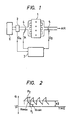
- This engine control system comprises an intake air flow sensor 2, an 0 2 sensor 5, a control circuit 3, and an injector (fuel injection valve) 4.
- the control circuit 3 includes a microcomputer and operates as follows.
- the intake air flow rate Q A is detected by the intake air flow sensor 2, and the output of the sensor 2 is input to the control circuit 3.
- the control circuit 3 determines the fuel injection amount in accordance with the detected intake air flow rate Q A and drives the injector 4 by a driving signal P,, thereby supplying the engine 1 with a predetermined amount of fuel.
- the control circuit 3 feedback-controls the driving of the injector 4 such that the air-fuel ratio of the air-fuel mixture sucked into the engine 1 is maintained in an optimum state.
- the pulse width T, of the driving signal P in this case is determined by the following formula 1: wherein are:
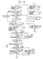
- the feedback control by the signal 0 2 from the 0 2 sensor 5 is effected by varying the control coefficient a in the manner shown in Figure 2. More specifically, the fuel supply amount is controlled by varying the control coefficient a such that the signal 0 2 periodically represents a richer state (a state wherein the air-fuel ratio is lower than the stoichiometric value) and a leaner state (a state wherein the air-fuel ratio is higher than the stoichiometric value), whereby the mean value of air-fuel ratios converges in proximity of the stoichiometric value (about 14.7).
- the value of the control coefficient a fluctuates around 1,0, and, therefore, the mean value of the air-fuel ratios is coincident with the stoichiometric value.
- the center value of the control coefficient a is shifted by the 0 2 feedback control in the direction in which the deviating air-fuel ratio may be corrected. For example, if the air-fuel ratio has become 10% lower (richer state) in order to correct the deviating air-fuel ratio, the control coefficient a is made to fluctuate around 0,9; when the air-fuel ratio has become 10% higher leaner state tho control coefficient a is made to fluctuate around 1,1. As a result, the mean value of air-fuel ratios is allowed to coincide with the stoichiometric value again, thus accomplishing air-fuel ratio feedback control.
- the above-described deviation of the air-fuel ratio from the stoichiometric value often occurs as the result of a change in the engine operating conditions.
- the above-described 0 2 feedback control involves the fact that, as the engine operating conditions change, the control coefficient a also changes: When the engine operational conditions are in a certain region, the control coefficient a fluctuates around 1,1; when the engine operational conditions are in another region, the control coefficient a fluctuates around 0,9.
- the above-described feedback control unavoidably involves a control delay. For this reason, even in the case where the engine operational conditions have shifted from one region to another region, and consequently the air-fuel ratio deviates from the stoichiometric value, feedback control which is initiated in order to correct the deviating air-fuel ratio takes some time to complete the correction: From the time when the control coefficient a shifts from a value corresponding to one region to a value corresponding to a new region to the time when the deviating air-fuel ratio is properly controlled such as to converge in proximity to the stoichiometric value.
- the engine is disadvantageously running in a state wherein the air-fuel ratio is not coincident with the stoichiometrical value.
- the engine operational conditions are subdivided into a multiplicity of sections in accordance with, for example, the magnitude of the load and the engine speed.
- the feedback control is effected by employing the deviation value corresponding to that section, whereby control can be effected under a state wherein the control coefficient a fluctuates around 1,0 at all times.
- the pulse width T, of the driving signal P, to be applied to the injector 4 is determined by the following formula 2: wherein
- the above-described deviation data K are successively written into the sections within the map constituted by a non-volatile memory, such as a power supply backup RAM, by learning during the engine operation, or the written data K, are rewritten in order to effect correction.
- a non-volatile memory such as a power supply backup RAM
- this learning control method it is not necessary to make preparations for the deviation data K, which are independent of each other by writing them into respective sections in the memory. Further, if there is a change in the characteristics of the engine and various actuators for control, the deviation data K, make self- correction in accordance with such change. It is, therefore, possible to effect correct control at all times and to maintain the engine in a correctly controlled state even when the engine operation is in a transient state.
- a predetermined condition is imposed on the writing of the deviation data in the conventional learning control method. More specifically, writing of the deviation data is executed only when the engine operational conditions are maintained in the same section within the memory map for a period of time which is longer than a predetermined value, and consequently it is possible to obtain deviation data which are measured in a state wherein the engine operation is sufficiently stable.
- This condition is a prerequisite for effecting a proper control by correct data and, therefore, it is almost impossible to avoid the above-described condition.
- deviation data in the memory map which respectively correspond to engine operation regions which hardly or only transiently appear in the actual engine operation are not rewritten indefinitely, and the initially set data are maintained as they are.
- the arrangement of an essential part of one embodiment of the present invention is the same as that of the system adopting the conventional learning control method shown in Figure 1.
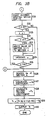
- the embodiment differs from the conventional system in that the process shown in the flow charts of Figures 3A, 38 is executed by the microcomputer comprised in the control circuit 3.
- step S1 the engine intake air amount Q A and the engine speed N are successively calculated in a step S1 (hereinafter, "step” will -be omitted, and only the reference symbols will be used, for example, "S1, S2 ... ”) and S2.
- step S3 data Tp are calculated from data Q A and N. It is to be noted that the data Tp are employed as a parameter for subdividing the engine operational conditions into sections.
- the signal 0 2 from the 0 2 sensor 5 is input to the control circuit 3.
- the signal 0 2 is successively examined in subsequent steps S5, S7.
- S5 judgement is made as to whether or not the signal 0 2 has changed from a richer state to a leaner state, that is, whether or not the control coefficient a is at the point P 1 in Figure 2. If the result of judgement is YES, the process proceeds to S6, in which the value of the control coefficient a is stored as ⁇ min , and the process proceeds to S9.
- the process jumps to S17, in which data K, are obtained from the data a meA" which have been calculated in S9 and are written in the section A within a non-volatile memory such as a power supply backup RAM.
- the result of judgement in S15 becomes YES when at least three conescutive YES's are judged in S11. This means that, while the engine operational conditions are in the same section within the map, the processing which took place up to S11 has been executed at least three times consecutively.
- processing is carried out up to S11 when the result of judgement in either S5 or S7 is YES, that is, when the control of the engine by the control coefficient a is effected exactly at either the point P 1 or P 2 in Figure 2.
- the fact that the result of judgement in S15 has become YES means that, with the engine operational conditions being in the same section within the map, the feedback control of the engine by the fluctuation of the control coefficient a shown in Figure 2 has been effected at least three times consecutively.
- the process proceeds to S19, in which the number of sections in which writing of data has been executed by the processing of S17 is examined with respect to all the sections within the memory map.
- the number of such sections is C. It is to be noted that, to obtain the number C, a method may be employed in which "0" has been written in all the sections within the memory map before the operation of the system is started, and in the processing of S19, the values of all the sections within the map are successively read out, and the number of the sections from which "0" is not read out is counted and determined to be the number C.
- Another method of obtaining the number C may be one in which a specific memory region prepared in the non-volatile memory is employed to constitute a soft counter, and the soft counter is incremented every time the processing of S17 is executed, and the data contained in the counter is examined in S19, thereby obtaining the number C.
- the process proceeds to the steps infra S26 while skipping over the processing of S21 to S25.
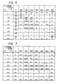
- Figure 4 shows an example of the memory map in accordance with this embodiment.
- the memory map shown in Figure 4 is divided into eight sections in each of the row and column directions, thereby providing a total of 64 sections.
- the memory map is divided in the row direction by the variable Tp which represents the engine load, and the memory map is divided in the column direction by the engine speed N.
- the section number x is consecutively given to the sections from the first row, from the left-hand side toward the right-hand side (as viewed in Figure 4), such that the section defined by the first row and the first column has the number 0, and the section defined by the eighth row and the eighth column has the number 63. It is to be noted that the section number x is shown in parentheses in a part within each section.
- the section number x is incremented by one. In other words, a processing is executed in which the number x is consecutively increased by one.
- the incremented section number x is examined, and judgement is made as to whether or not the section number x is 63 or smaller, the number 63 representing the total number of sections within the memory map. As long as the result of judgement is YES, the process returns to S22, and the processing of S22 to S24 is repeated.
- steps S26 to S30 The processing carried out in steps S26 to S30 is necessary for the control of the injector 4.
- data K are read out from section A within the memory map. Section A in this case has been judged in either S10 or S31 and represents the region of the present engine operational conditions.
- the coefficients K 2 , T. are successively calculated.
- the process proceeds to S29, in which data T, representing the pulse width required for the driving signal P which is to be applied to the injector 4 is calculated from the control coefficient a, the data K,, the variable Tp, etc.
- the data T are set in a predetermined injector controlling register by the processing of S30, thus ending the process according to the flow chart shown in Figures 3A and 3B.
- the number of sections within the memory map namely, the number of sections corresponding to engine operational condition regions for effecting feedback control
- the number of sections into which leaning control data have already been written reaches 25, data which are approximate to the learning control data are written into the other sections in the memory map.
- the total number of the sections is not necessarily limited to 64 and may be set as desired. Further, the above-described number 25 of the sections may, as a matter of course, also be set as desired.
- the method of writing the approximate data employed in the above-described embodiment is as follows: By the processing of steps S20 to S25, approximate data which are to be written into each of the sections in which writing of data has not yet been completed is selected to be the data in the section which is both one into which learning control data have already been written and is also the first section to be found when tracing backwardly through the sections, that is, from a given section to the preceding section whose number is by one smaller than that of the former.
- the above-described method is not necessarily limitative, and the present invention can be carried out in various forms.
- data may be written which are a mean value of the data contained in these two sections.
- mean value may be obtained by averaging the data contained in two sections adjacent to each other in the column direction and the data contained in two sections adjacent to each other in the row direction.
- the present invention is applied to the air-fuel ratio control system
- the invention is not limited to air-fuel ratio control systems, but is, as a matter of course, also applicable to any system adoping the learning control method.
- the invention may also be applied to a knocking control system.
- the first embodiment of the present invention is designed such that, in an engine control system adopting the learning control method, when the number of sections in which data have already been written reaches a predetermined value with respect to the total number of sections within a memory which stores data for control, data are forcedly written into each of the other sections into which no data have been written, this data already being stored in nearby sections in which writing of data has already been completed, whereby almost all the sections within the memory map are allowed to have data stored therein, thereby overcoming the disadvantages of the prior art and enabling an appropriate control to be effected at all times.
- a second embodiment of the present invention which will be described hereinunder is arranged such as to overcome the above-described disadvantage of the first embodiment of the invention.
- the fundamental arrangement of the second embodiment is the same as that of the first embodiment, as will be clear from the following description.
- an engine control method and apparatus which are free from the possibility of incorrect control even when forced writing of data is executed with respect to all the sections within the memory map into which no data have been written and which apparatus is consequently able to effect excellent control at all times.
- the second embodiment of the present invention with respect to a section within the memory map in which, although the condition of writing deviation data is satisfied as the result of feedback control, the deviation of the feedback control value from the reference value is so small that it can be regarded as zero, and it is, consequently, judged that writing of deviation data should not be executed therein, data are written which represent a value determined on the basis of a minimum resolving power by which data can be written into the memory map so that the written data represent the fact that the section is one in which writing of data has already been completed, whereby data representing an improper value are prevented from being written by the forced writing of data.
- the second embodiment of the present invention the arrangement of its essential part is the same as that of the system adopting the conventional learning control method shown in Figure 1. According to the second embodiment, the process shown in the flow charts of Figures 3A and 3B is executed by the microcomputer incorporated in the control circuit 3.
- the second embodiment differs from the first embodiment in that the second embodiment includes steps S16 and S18 in the process shown in Figures 3A and 3B.
- the process proceeds to S16, in which judgement is made as to whether or not the data am..n calculated in S9 are 1. If the result of judgement is NO, the process proceeds to S17, in which data K, are calculated from the data a m .. n calculated in S9 and are written into a section A, for example, within the map constituted by a non-volatile memory such as power supply backup RAM.
- Another method of obtaining the number C may be one in which a specific memory region prepared in the non-volatile memory is employed to constitute a soft counter, and the soft counter is incremented every time the processing of either S17 or S18 is executed, and the data contained in the counter are examined in S19, thereby obtaining the number C.
- the number C is compared with a predetermined number, e.g., 25, in the subsequent step S20, thereby making a judgement as to whether or not the number C is 25 or larger.
- a predetermined number e.g. 25, in the subsequent step S20.
- the process proceeds to the steps infra S26 while skipping over the processing of steps S21 to S25.
- the processing taking place thereafter is the same as that in the case of the first embodiment of the present invention.
- Figure 6 shows an example of the memory map in accordance with the second embodiment.
- the memory map shown in Figure 6 is divided into eight sections in each of the row and column directions, thereby providing a total of 64 sections.
- the memory map is divided in the row direction by the variable Tp which represents the engine load, and the memory map is divided in the column direction by the engine speed N.
- the section number x is consecutively given to the sections from the first row, from the left-hand side toward the right-hand side (as viewed in Figure 6), such that the section defined by the first row and the first column has the number 0, and the section defined by the eighth row and the eighth column has the number 63. It is to be noted that the section number x is shown in parentheses in a part within each section.
- the section number x is incremented by one. In other words, a processing is executed in which the number x is consecutively increased by one.
- the incremented section number x is examined, and judgement is made as to whether or not the section numberx is 63 or smaller, the number 63 representing the total number of sections within the memory map. As long as the result of judgement is YES, the process returns to S22, and the processing or steps S22 to S24 is repeated.
- the injector 4 when the number of sections into which data have already been written reaches a predetermined value with respect to the total number of sections within the memory map, approximate data are written into almost all the sections into which no data have been written. Moreover, in this case, with respect to a section into which data "0" should have been written, a numerical value is written which is sufficiently large for representing the fact that writing of data in that section has already been completed and which is, at the same time, a very small value that can be regarded as zero from the viewpoint of control, for example, 0,001. Therefore, there is no possibility that an improper numerical value may be written into such a section. Thus, it is possible to effectively eliminate the air-fuel ratio control delay due to the existence of sections in which writing of data has not yet been completed and to obtain high accuracy in control. Accordingly, it is possible to satisfactorily prevent a deterioration of the exhaust gas composition.
- the second embodiment shown in Figure 6 into these sections is written 0,001 which is the minimum numerical value which can be written into the memory, the value representing the fact that it is no longer necessary to forcedly write any data into the sections.
- the electronic control apparatus according to the invention is able to satisfactorily compensate for a feedback control delay at all times and to satisfactorily effect an appropriate control even when the engine is in a transient state, thereby making it possible to maintain the exhaust gas composition in an excellent state at all times.
Landscapes
- Engineering & Computer Science (AREA)
- Chemical & Material Sciences (AREA)
- Combustion & Propulsion (AREA)
- Mechanical Engineering (AREA)
- General Engineering & Computer Science (AREA)
- Computer Hardware Design (AREA)
- Microelectronics & Electronic Packaging (AREA)
- Combined Controls Of Internal Combustion Engines (AREA)
- Electrical Control Of Air Or Fuel Supplied To Internal-Combustion Engine (AREA)
Claims (4)
gekennzeichnet durch folgende Stufen:
die folgende Stufen durchführt:
dadurch gekennzeichnet, daß der Steuerkreis so ausgelegt ist, daß folgende Stufen durchgeführt werden:
Applications Claiming Priority (2)
| Application Number | Priority Date | Filing Date | Title |
|---|---|---|---|
| JP11822/84 | 1984-01-27 | ||
| JP59011822A JPS60156953A (ja) | 1984-01-27 | 1984-01-27 | 電子式内燃機関制御装置 |
Publications (3)
| Publication Number | Publication Date |
|---|---|
| EP0152001A2 EP0152001A2 (de) | 1985-08-21 |
| EP0152001A3 EP0152001A3 (en) | 1986-01-15 |
| EP0152001B1 true EP0152001B1 (de) | 1988-10-19 |
Family
ID=11788468
Family Applications (1)
| Application Number | Title | Priority Date | Filing Date |
|---|---|---|---|
| EP85100826A Expired EP0152001B1 (de) | 1984-01-27 | 1985-01-28 | Verfahren und Vorrichtung zur Steuerung von Brennkraftmaschinen |
Country Status (5)
| Country | Link |
|---|---|
| US (1) | US4566420A (de) |
| EP (1) | EP0152001B1 (de) |
| JP (1) | JPS60156953A (de) |
| KR (1) | KR890002866B1 (de) |
| DE (1) | DE3565710D1 (de) |
Families Citing this family (13)
| Publication number | Priority date | Publication date | Assignee | Title |
|---|---|---|---|---|
| US4703430A (en) * | 1983-11-21 | 1987-10-27 | Hitachi, Ltd. | Method controlling air-fuel ratio |
| DE3408215A1 (de) * | 1984-02-01 | 1985-08-01 | Robert Bosch Gmbh, 7000 Stuttgart | Steuer- und regelverfahren fuer die betriebskenngroessen einer brennkraftmaschine |
| DE3590028T (de) * | 1984-01-24 | 1986-02-06 | Japan Electronic Control Systems Co, Ltd., Isesaki, Gunma | Lernfähige Brennstoffeinspritz-Regelvorrichtung |
| JPS6125949A (ja) * | 1984-07-13 | 1986-02-05 | Fuji Heavy Ind Ltd | 自動車用エンジンの電子制御方法 |
| JPS6176733A (ja) * | 1984-09-10 | 1986-04-19 | Mazda Motor Corp | エンジンの空燃比制御装置 |
| JPS61169634A (ja) * | 1985-01-21 | 1986-07-31 | Aisan Ind Co Ltd | 内燃機関の混合気供給システムのための燃料供給量制御装置 |
| DE3505965A1 (de) * | 1985-02-21 | 1986-08-21 | Robert Bosch Gmbh, 7000 Stuttgart | Verfahren und einrichtung zur steuerung und regelverfahren fuer die betriebskenngroessen einer brennkraftmaschine |
| US4770147A (en) * | 1986-04-25 | 1988-09-13 | Fuji Jukogyo Kabushiki Kaisha | Air-fuel ratio control system for an engine |
| GB2194359B (en) * | 1986-08-02 | 1990-08-22 | Fuji Heavy Ind Ltd | Air-fuel ratio control system for an automotive engine |
| JPS6350644A (ja) * | 1986-08-13 | 1988-03-03 | Fuji Heavy Ind Ltd | エンジンの空燃比制御装置 |
| JPH0751907B2 (ja) * | 1987-03-11 | 1995-06-05 | 株式会社日立製作所 | 空燃比学習制御装置 |
| DE3811262A1 (de) * | 1988-04-02 | 1989-10-12 | Bosch Gmbh Robert | Lernendes regelungsverfahren fuer eine brennkraftmascchine und vorrichtung hierfuer |
| DE4142155A1 (de) * | 1991-12-20 | 1993-06-24 | Bosch Gmbh Robert | Digitales adaptives regelungssystem und -verfahren, insbesondere fuer einen verbrennungsmotor |
Family Cites Families (12)
| Publication number | Priority date | Publication date | Assignee | Title |
|---|---|---|---|---|
| US4130095A (en) * | 1977-07-12 | 1978-12-19 | General Motors Corporation | Fuel control system with calibration learning capability for motor vehicle internal combustion engine |
| JPS5596339A (en) * | 1979-01-13 | 1980-07-22 | Nippon Denso Co Ltd | Air-fuel ratio control method |
| US4235204A (en) * | 1979-04-02 | 1980-11-25 | General Motors Corporation | Fuel control with learning capability for motor vehicle combustion engine |
| JPS569633A (en) * | 1979-07-02 | 1981-01-31 | Hitachi Ltd | Control of air-fuel ratio for engine |
| JPS5654936A (en) * | 1979-10-10 | 1981-05-15 | Nippon Denso Co Ltd | Control method for air-fuel ratio |
| JPS5768544A (en) * | 1980-10-17 | 1982-04-26 | Nippon Denso Co Ltd | Controlling method for internal combustion engine |
| JPS57137632A (en) * | 1981-02-20 | 1982-08-25 | Honda Motor Co Ltd | Electronic fuel injection device of internal combustion engine |
| JPS5810126A (ja) * | 1981-07-09 | 1983-01-20 | Toyota Motor Corp | 電子制御燃料噴射機関の補正値算出方法 |
| JPS5888435A (ja) * | 1981-11-19 | 1983-05-26 | Honda Motor Co Ltd | 吸気温度による補正機能を有する内燃エンジンの空燃比補正装置 |
| JPS58192945A (ja) * | 1982-05-06 | 1983-11-10 | Honda Motor Co Ltd | 内燃エンジンの空燃比フィ−ドバック制御装置 |
| JPS58222939A (ja) * | 1982-05-28 | 1983-12-24 | Honda Motor Co Ltd | 内燃エンジンの酸素濃度検出系故障時の空燃比制御方法 |
| JPS58217749A (ja) * | 1982-06-11 | 1983-12-17 | Honda Motor Co Ltd | 内燃エンジンの特定運転状態時の燃料供給制御方法 |
-
1984
- 1984-01-27 JP JP59011822A patent/JPS60156953A/ja active Pending
-
1985
- 1985-01-26 KR KR1019850000491A patent/KR890002866B1/ko not_active Expired
- 1985-01-28 EP EP85100826A patent/EP0152001B1/de not_active Expired
- 1985-01-28 US US06/695,246 patent/US4566420A/en not_active Expired - Fee Related
- 1985-01-28 DE DE8585100826T patent/DE3565710D1/de not_active Expired
Also Published As
| Publication number | Publication date |
|---|---|
| JPS60156953A (ja) | 1985-08-17 |
| DE3565710D1 (en) | 1988-11-24 |
| KR890002866B1 (ko) | 1989-08-05 |
| EP0152001A3 (en) | 1986-01-15 |
| KR850005554A (ko) | 1985-08-26 |
| US4566420A (en) | 1986-01-28 |
| EP0152001A2 (de) | 1985-08-21 |
Similar Documents
| Publication | Publication Date | Title |
|---|---|---|
| EP0152001B1 (de) | Verfahren und Vorrichtung zur Steuerung von Brennkraftmaschinen | |
| US5065728A (en) | System and method for controlling air/fuel mixture ratio of air and fuel mixture supplied to internal combustion engine using oxygen sensor | |
| EP0571182B1 (de) | Steuersystem für das Luft-/Kraftstoff-Verhältnis einer Brennkraftmaschine | |
| US5179929A (en) | Method of detecting deterioration of exhaust gas ingredient concentration sensor | |
| JP2742431B2 (ja) | エンジンの空燃比制御装置 | |
| US4625699A (en) | Method and apparatus for controlling air-fuel ratio in internal combustion engine | |
| EP1030045B1 (de) | SELBSTADAPTIERENDES Verfahren zur Steuerung des Kraftstoffsgemisches einer Brennkraftmaschine | |
| JPS6346254B2 (de) | ||
| EP0281962B1 (de) | Steuervorrichtung für Brennkraftmaschinen | |
| US5487270A (en) | Air-fuel ratio control system for internal combustion engine | |
| US4723408A (en) | Double air-fuel ratio sensor system carrying out learning control operation | |
| US4747385A (en) | Air-fuel ratio control system for an automotive engine | |
| JPH0345224B2 (de) | ||
| JPH07107376B2 (ja) | 自動車用エンジンの学習制御方法 | |
| JPS62195439A (ja) | エンジンの制御装置 | |
| JPH06229293A (ja) | エンジンの空燃比制御装置 | |
| JPS62210235A (ja) | 内燃機関の空燃比学習制御装置 | |
| JP2631585B2 (ja) | 内燃機関の空燃比学習制御装置 | |
| JPS60153504A (ja) | 学習機能付フイ−ドバツク制御装置 | |
| JPH0243900B2 (ja) | Nainenkikannogakushuseigyosochi | |
| JPH01130033A (ja) | 内燃エンジンの空燃比制御方法 | |
| JPH04318246A (ja) | 内燃機関の空燃比学習制御装置 | |
| JPH07269398A (ja) | 内燃機関の空燃比制御装置 | |
| JPH07119521A (ja) | 内燃機関の空燃比学習制御装置 | |
| JPH04237847A (ja) | 内燃機関の空燃比学習制御装置 |
Legal Events
| Date | Code | Title | Description |
|---|---|---|---|
| PUAI | Public reference made under article 153(3) epc to a published international application that has entered the european phase |
Free format text: ORIGINAL CODE: 0009012 |
|
| AK | Designated contracting states |
Designated state(s): DE GB |
|
| PUAL | Search report despatched |
Free format text: ORIGINAL CODE: 0009013 |
|
| AK | Designated contracting states |
Designated state(s): DE GB |
|
| 17P | Request for examination filed |
Effective date: 19860117 |
|
| 17Q | First examination report despatched |
Effective date: 19870213 |
|
| GRAA | (expected) grant |
Free format text: ORIGINAL CODE: 0009210 |
|
| AK | Designated contracting states |
Kind code of ref document: B1 Designated state(s): DE GB |
|
| REF | Corresponds to: |
Ref document number: 3565710 Country of ref document: DE Date of ref document: 19881124 |
|
| PLBE | No opposition filed within time limit |
Free format text: ORIGINAL CODE: 0009261 |
|
| STAA | Information on the status of an ep patent application or granted ep patent |
Free format text: STATUS: NO OPPOSITION FILED WITHIN TIME LIMIT |
|
| 26N | No opposition filed | ||
| PGFP | Annual fee paid to national office [announced via postgrant information from national office to epo] |
Ref country code: GB Payment date: 19920117 Year of fee payment: 8 |
|
| PGFP | Annual fee paid to national office [announced via postgrant information from national office to epo] |
Ref country code: DE Payment date: 19920324 Year of fee payment: 8 |
|
| PG25 | Lapsed in a contracting state [announced via postgrant information from national office to epo] |
Ref country code: GB Effective date: 19930128 |
|
| GBPC | Gb: european patent ceased through non-payment of renewal fee |
Effective date: 19930128 |
|
| PG25 | Lapsed in a contracting state [announced via postgrant information from national office to epo] |
Ref country code: DE Effective date: 19931001 |