EP0151997B1 - Broyeur cylindrique - Google Patents
Broyeur cylindrique Download PDFInfo
- Publication number
- EP0151997B1 EP0151997B1 EP85100817A EP85100817A EP0151997B1 EP 0151997 B1 EP0151997 B1 EP 0151997B1 EP 85100817 A EP85100817 A EP 85100817A EP 85100817 A EP85100817 A EP 85100817A EP 0151997 B1 EP0151997 B1 EP 0151997B1
- Authority
- EP
- European Patent Office
- Prior art keywords
- pressure
- roller
- rollers
- roller mill
- displacement
- Prior art date
- Legal status (The legal status is an assumption and is not a legal conclusion. Google has not performed a legal analysis and makes no representation as to the accuracy of the status listed.)
- Expired
Links
Images

Classifications
-
- B—PERFORMING OPERATIONS; TRANSPORTING
- B02—CRUSHING, PULVERISING, OR DISINTEGRATING; PREPARATORY TREATMENT OF GRAIN FOR MILLING
- B02C—CRUSHING, PULVERISING, OR DISINTEGRATING IN GENERAL; MILLING GRAIN
- B02C4/00—Crushing or disintegrating by roller mills
- B02C4/28—Details
- B02C4/32—Adjusting, applying pressure to, or controlling the distance between, milling members
- B02C4/36—Adjusting, applying pressure to, or controlling the distance between, milling members in mills specially adapted for paste-like materials
Definitions
- the invention relates to a rolling mill according to the preamble of claim 1.
- Rolling mills with adjusting devices for interleaving at least one roll have been proposed variously in the literature in order to avoid the need for roll crowning. Examples of such constructions can be found in FR-A-1 028 098 and FR-A-1 273 350 as well as in US-A-2 762 295. Rolling mills of this type are usually operated at a specific operating pressure which corresponds to a predetermined crowning of the rollers or a predetermined entanglement. Therefore, the known rolling mills were only equipped with a manual adjustment according to the cited references, the respective master being able to adjust the size of the adjustment with the aid of a key.
- the invention is therefore based on the object of finding a practical solution for the automatic adjustment of the entanglement depending on the pressure (or vice versa) in rolling mills in which the pressure exerted on the rollers is several hundred kilos, in particular more than one ton, e.g. is over 4t.
- This object is achieved by the features of the characterizing part of claim 1.
- the features of claim 2 are provided for realizing such pressures.
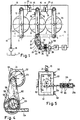
- the two outer rolls 1 are mounted in bearings 69, 70 on levers 5 and 6, respectively, which can be pivoted about a fixed axis 3 or 4.
- the two outer rollers 1 are braced via the levers 5, 6 with the aid of fluidic piston-cylinder units 7, 8 against a lever 10 carrying the middle roller 9.
- the connection between the levers 5, 6 and 10 or the units 7, 8 is only shown schematically as a line, but it goes without saying that between the outer levers 5, 6 and the respective piston-cylinder unit 7 and 8, the connection via the respective piston rod 11 or 12 articulated on the lever 5 or 6 takes place, whereas the respective cylinder 13 or 14 is connected to the central lever 10 via a rod 15 or 16 articulated on the lever 10.
- the piston-cylinder units 7, 8 are supplied with pressure medium, in particular a pressure fluid from a reservoir 17 with the aid of a pump 18, to which a pressure line 19 is connected.
- the pressure line 19 opens via a branch line 20 into the cylinder 13 of the unit 7 and finally also into the cylinder 14 of the unit 18.
- This guide rocker 68 preferably swings about a horizontal plane 73 passing through its pivot bearing 4, since the deviations from a straight line thus remain small.
- the rocker 68 can also be arranged on the top of the levers 6, 10 if the units 7, 8 engage on the underside, or a bearing that is independent of the lever 6 or frame part (if the roller 2 is to be stationary) have, but the joint use of the bearing 4 is easier on the one hand, on the other hand, it has proven to be advantageous if the length of the rocker 68 corresponds to the distance to the adjacent roller, that is to say approximately the diameter of a roller. An effect is obtained with simpler means, as has already been described in FR-A-1 273 350.
- a connecting rod 22 is articulated on the axis 21, which comprises an adjusting eccentric 23 at its lower end.
- an eccentric the width of which can be selected according to the construction, the pressure is transferred to a relatively large area, so that there is no too much high surface pressures, as would be the case with cams, for example.
- the eccentric 23 is seated on a stationary shaft 24 which runs parallel to the middle roller 9 and at the opposite end carries an eccentric for adjusting the bearing lever provided on this side and corresponding to the lever 10.
- the arrangement is such that the eccentricity of the two adjustment eccentrics is rotated relative to one another by 180 ° in a known manner, so that when the middle roller 9 is adjusted upwards on one side, the adjustment takes place downwards on the other side and thus entanglement of the middle roller 9 with respect to the outer rollers 1 about an axis passing through the middle of their length.
- an electrical pressure sensor 26 is provided in the pressure line 19, the output signal of which is fed to a control stage 27, which is due to a comparison with a setpoint, which may be adjustable, outputs an adjustment signal to a motor control stage 28.
- the associated motor 29 can be any motor (in which case a closed control loop for the eccentric adjustment is expedient), but is preferably a stepper motor, so that the adjustment of the eccentric 23 attached to the continuous shaft 24 is dependent on the direction of rotation of the motor 29 and the number of step pulses supplied to it.
- a closed control loop for the eccentric adjustment is expedient
- stepper motor so that the adjustment of the eccentric 23 attached to the continuous shaft 24 is dependent on the direction of rotation of the motor 29 and the number of step pulses supplied to it.
- the rotor of the stepper motor 29 carries a threaded spindle 30, into which a lock nut 31 is screwed.
- the lock nut 31 is prevented from rotating by stationary axial guides 32 and laterally projecting wings 33.
- a connecting rod 34 is connected to the lock nut 31 and is connected to the crank pin 36 of the crank 25 via a transverse slot 35. It is understood from the later description that an amplifier 48 to 52 according to FIG. 3 can be provided between stepper motor 29 and crank 25.
- FIG. 2 the relationship between the crowning height B, which is necessary per se and which can be replaced by the entanglement, in applied pressure in tons (to) is shown in FIG. 2.
- the shaft 24 can be driven in the manner described with reference to FIG. 1 via a push crank 25, which is arranged opposite the adjusting eccentric 23 in such a way that a linear adjustment movement by the servomotor 29 due to the sinusoidal movement of the crank pin 36 occurs there is an adjustment corresponding to curve 39 in FIG. 2, the bulging of the dash-dotted curve 38 being essentially compensated in this way.
- the crank 25 (FIG. 1) can be adjustable, for example, in its angular position relative to the eccentrics (see FIG. 23), or a plurality of fastening holes 40 are provided for the crank pin 36.
- the pressure line 19 can be connected directly to a connecting line 41 which leads to a converter unit 42.
- a piston 43 is acted upon directly by the pressure and accordingly moves against the pressure of a spring 44. Since the force of the spring increases, a position of the piston 43 arises where the equilibrium between the spring pressure of the spring 44 and the pressure results the pressure line 19 is made.
- a suspension formed by a quantity of gas, a magnetic counterforce or the like could also be provided, but the spring 44 is cheap in that it has a linear characteristic and therefore the pressure prevailing in the pressure line 19 is linear Way is converted.
- a non-linear pressure element is provided precisely for the purpose of the compensation discussed with reference to FIG. 2.
- the piston 43 is connected to a piston rod 45 which, at its left end (with reference to FIG. 3), is a control element per se Known servo amplifier is formed, which is connected directly to the pressure pump 18 via a line 46, whereas a reducing valve 47 is interposed against the pressure line 19.
- the piston rod 45 with control edges 48, 49 of widened diameter controls the inflow of the hydraulic medium from the line 46 via channels 50, 51 to one side of a servo piston 52, which in turn adjusts itself relative to the piston rod 45 until it runs out Fig. 3 apparent position is reached, in which both channels 50, 51 are closed off against the line 47.
- the movement of the servo piston 52 is then transferred to the crank 25 in a similar manner as was shown with reference to FIG. 1.
- an adjustment possibility is expediently provided within a slot 74.
- the middle roller 9 is mounted stationary, whereas the levers 5, 6 are adjustable in height by means of adjusting eccentrics 23.
- an adjustment by a single common eccentric 23 would be possible, which acts on a carrier that is just guided, but the solution shown offers the possibility of a separate adjustment of both levers 5, 6 and also saves the complicated straight guidance.
- the solution shown is particularly suitable for five-roll mills in which two further rolls are connected on both sides of the rolls 1, 2.
- FIGS. 4 and 5 show a solution in which the push rod 134 corresponding to the rod 34 is designed as a toothed rack and is in engagement with a toothed wheel 53 on the shaft 54 of a drive eccentric 55.
- the drive eccentric 55 is surrounded by a connecting rod 56. which carries the shaft 24 at its upper end.
- the shaft 24 receives its drive from a sprocket 57 seated on the shaft 54, which is connected via a chain 58 to a further sprocket 59 wedged onto the shaft 24.
- a tensioning roller (not shown) for the chain can be provided at 60.
- servo amplifiers 48 to 52 of the type shown in FIG. 3 can also be used to directly control reciprocating pistons on both sides of the roller 9, it only being necessary to ensure that the movement of these pistons on the two sides of the roller 9 takes place in the opposite direction.
- Such a solution can be particularly advantageous if, for example, several rolls are to be interlaced, in particular in a rolling mill with at least 4 rolls.
- FIG. 5 Another solution for the adjustment mechanism is shown in FIG. 5, in which the bearing lever 10 for the shaft of the roller 9 (cf. FIGS. 1, 3) is mounted on a frame 61.
- This frame 61 is vertically displaceable with the aid of sliding guides 62 and has on one side a toothed rail 63 into which a gearwheel 64 fixed on a fixedly mounted shaft 124 engages.
- the arrangement on the other side of the roller 9 is essentially the same, but with the difference that there the gear corresponding to the gear 64 is not on the right-hand side (with reference to FIG. 5), but on the left-hand side in a toothed rail provided there engages the frame.
- the frames 61 accordingly move in different directions on both sides.
- the drive rod can consist of two interconnected parts 234, 334, of which the rack 334 has thickened portions 65, which can optionally be inserted into different recesses in the rod 234, the two rod parts 234, 334 then being connected by means of fastening screws 67.
- this type of adjustment however, only the height of the desired crowning can be set, the curve profile being unaffected for the adjustment characteristic of the entanglement.
- the adjustment path transferred to the bearing of the roll to be entangled is in a certain ratio to the compensating movement.
- a stroke of crank 25 or eccentric 55 that is too large would result in a compensation curve that is too flat and long.
- the height adjustment path for the roller to be crossed is not only dependent on the contact pressure, but also on the lever length, i.e. depends on the distance between the center of the roller and the point of application of the bearing lever 10 or 5.6.
- the ratio between the height adjustment path of the respective bearing lever 10 (FIG. 1) or 5, 6 (FIG. 3) to the length of the crank 25 is between 1: 3 and 1: 5.
- the curve shape that can be achieved by entangling does not exactly correspond to the mathematical conditions of crowning. This may also be a reason why the entanglement has so far been used relatively rarely and mostly only for low roller pressures.
- a crown ground on a roller cannot be adapted to different pressures, so that a certain deviation from the ideal shape is always accepted, particularly in the case of large pressure adjustment ranges got to.
- a way out of this dilemma can now be in a rolling mill with at least two rollers and a pressure device for loading at least one roller against the other, and an adjusting device for interlocking the rollers, in that at least one of the rollers 1, 2, 9 which can be offset relative to one another additionally has a crowning, which corresponds to a lower range of the operating pressure.
- a basic crowning is specified, from which an entanglement is made.
- the basic crowning can be designed in such a way that the mathematical error resulting from entanglement is at least partially (preferably approximately half) compensated.
- the basic crowning mentioned can be provided on at least one of the rollers 1, 2 and 9, but is preferably present on at least that roller which is adjusted to be entangled, i.e. in the case of FIG. 1 on the roller 9, in the case of FIG. 3 on the rollers 1 and 2, in particular when it is a five-roll mill in the manner described.
- all the rollers have the basic crowning mentioned, which of course does not have to be the same on all rollers and differs from the crowning of the peripheral rollers, in particular on the central rollers.
- the adjustment range of the pressure can have a ratio of 1: 6 between minimum and maximum pressure. If one assumes that the minimum pressure is 1, then the basic crowning must be calculated for a pressure of at most 3, the pressure selected for the calculation in practice being significantly lower. For example, the pressure used for the calculation is 1.5 to 2, but can also be selected with 1.
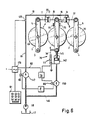
- FIG. 6 shows that not only a simple control, but also a closed control loop can be used to set the mutual entanglement of the roller 9 with respect to the stationary rollers 1, 2. Parts of the same function have the same reference numerals as in the previously described figures, possibly provided with a 100 number.
- a carrier 110 that can be displaced in the vertical direction (based on FIG. 6) in the sliding guides 75 is mounted on a piston rod 145 of a hydraulic lifting unit 142.
- the unit 142 is connected to the pump 18 via a line 146.
- An electrically controllable solenoid valve 150 which regulates the inflow of hydraulic fluid to the unit 142, is located in the line 146.
- a position sensor 76 is connected to the carrier 110 of the roller 9, which position can be constructed as desired, but in the arrangement shown has two stationary (for example connected to the unit 142) capacitor plates 77, between which an insulating plate 78 connected to the carrier 110 immersed. Depending on the actual position of the carrier 110, this results in a correspondingly different signal at the output of the position transmitter 76, which output signal can be fed to a control circuit 79.
- control loop 79 represents only part of the control system, to which a second controller 179 belongs. It goes without saying that both control loops 79, 179 can optionally be combined to form one structural unit. Since the control loop 179 with a z. B. is connected by a keyboard device, setpoint input device 81, a connecting line 82 is expediently provided to the control circuit 79 in order to transmit a corresponding signal. If appropriate, this connecting line 82 is designed as a data bus, via which any feedback from the control circuit 79 to the controller 179 can also take place.
- a control signal for the magnet 80 of the solenoid valve 150 is generated at the output of the control circuit 79, which can also be fed to the magnet 83 of the controllable valve 147 provided in the line 19 via a proportional element P.
- a simple valve 47 according to FIG. 3 can also be provided here, the adjustment of which by a Input device 181 of any type is determined.
- the magnet 83 is connected to the controller 179, which connects it to a voltage source on the one hand on the basis of the setpoint signal received from the input device 81 or on the other hand based on the signal of a pressure detector 126.
- adjustment paths for the entanglement of the roller axes can of course be halved in that two adjacent rollers are adjusted in opposite directions.
Landscapes
- Engineering & Computer Science (AREA)
- Food Science & Technology (AREA)
- Rolls And Other Rotary Bodies (AREA)
- Crushing And Grinding (AREA)
Claims (10)
par le fait que l'extrémité libre de la biellette de guidage (68) est de préférence articulée sur le pivot (3,4) d'un levier (5, 6) qui porte le palier (69, 70) du cylindre, et/ou la biellette de guidage (68) peut pivoter autour d'un plan (73) qui passe par son pivot (4), et s'étend sensiblement perpendiculairement à la direction du réglage.
Applications Claiming Priority (2)
| Application Number | Priority Date | Filing Date | Title |
|---|---|---|---|
| DE19843404932 DE3404932A1 (de) | 1984-02-11 | 1984-02-11 | Walzwerk |
| DE3404932 | 1984-02-11 |
Publications (3)
| Publication Number | Publication Date |
|---|---|
| EP0151997A2 EP0151997A2 (fr) | 1985-08-21 |
| EP0151997A3 EP0151997A3 (en) | 1986-12-03 |
| EP0151997B1 true EP0151997B1 (fr) | 1988-12-14 |
Family
ID=6227468
Family Applications (1)
| Application Number | Title | Priority Date | Filing Date |
|---|---|---|---|
| EP85100817A Expired EP0151997B1 (fr) | 1984-02-11 | 1985-01-26 | Broyeur cylindrique |
Country Status (4)
| Country | Link |
|---|---|
| US (1) | US4635861A (fr) |
| EP (1) | EP0151997B1 (fr) |
| JP (1) | JPS60183044A (fr) |
| DE (2) | DE3404932A1 (fr) |
Families Citing this family (20)
| Publication number | Priority date | Publication date | Assignee | Title |
|---|---|---|---|---|
| DE3702245C3 (de) * | 1987-01-27 | 1993-12-23 | Kleinewefers Gmbh | Kalander |
| DE8801758U1 (de) * | 1987-08-28 | 1988-05-05 | Sulzer-Escher Wyss AG, Zürich | Druckwalze |
| DE3901060A1 (de) * | 1989-01-16 | 1990-07-19 | Kloeckner Humboldt Deutz Ag | Zweiwalzenmaschine, insbesondere walzenbrecher |
| US5072887A (en) * | 1990-01-19 | 1991-12-17 | California Pellet Mill Company | Roll mill |
| DE4226158C2 (de) * | 1992-08-07 | 2003-04-10 | Kloeckner Humboldt Wedag | Verfahren und Anlage zur Druckbehandlung körnigen Gutes |
| CA2175879A1 (fr) * | 1995-05-17 | 1996-11-18 | Wolfgang Finken | Concasseur a cylindres |
| ITMI980943A1 (it) * | 1998-04-30 | 1999-10-30 | Carle & Montanari Spa | Procedimento e dispositivo per la premacinazione di materiale dolciario |
| US6238724B1 (en) * | 1998-10-29 | 2001-05-29 | Kraft Foods, Inc. | Chocolate refining process |
| US6920772B1 (en) | 2003-02-12 | 2005-07-26 | Morgan Construction Company | Pinch roll unit |
| DE102004052084B4 (de) * | 2004-10-26 | 2016-10-27 | Bühler AG | Walzwerk |
| WO2007055672A1 (fr) | 2005-09-16 | 2007-05-18 | Yukselis Makina Sanayi Ve Ticaret Anonim Sirketi | Agencement de positionnement angulaire de rouleaux de broyage |
| US7275404B1 (en) | 2005-11-22 | 2007-10-02 | Og Technologies, Inc. | Method and an apparatus to control the lateral motion of a long metal bar being formed by a mechanical process such as rolling or drawing |
| US7861567B2 (en) | 2005-11-22 | 2011-01-04 | Og Technologies, Inc. | Method and apparatus to control the lateral motion of a long metal bar being formed by a mechanical process such as rolling or drawing |
| TR200704949U (tr) * | 2007-07-16 | 2007-08-21 | Yükseli̇ş Maki̇na San. Ti̇c.A. Ş. | Eksantrik burçlu moment kollu yataklama paketi. |
| US7794346B2 (en) * | 2008-02-01 | 2010-09-14 | William Lake | Torque transfer device |
| US20100221081A1 (en) * | 2009-02-27 | 2010-09-02 | Leite Paulo Cesar De Andrade | System for automation of fluctuation and leveling of top rollers of sugarcane mills |
| CN102441459A (zh) * | 2011-12-14 | 2012-05-09 | 吴江市冰心文教用品有限公司 | 一种三辊研磨机 |
| EP2746024B1 (fr) * | 2012-12-21 | 2015-05-27 | Reifenhäuser GmbH & Co. KG Maschinenfabrik | Siège de cylindre |
| CN112774781A (zh) * | 2020-12-09 | 2021-05-11 | 上海铸研重工科技有限公司 | 摆辊式制砂机 |
| CN120861199B (zh) * | 2025-09-26 | 2025-11-28 | 常州市龙鑫智能装备股份有限公司 | 辊筒间距和压力检测的联动调节机构、调节方法及三辊机 |
Family Cites Families (16)
| Publication number | Priority date | Publication date | Assignee | Title |
|---|---|---|---|---|
| DE504851C (de) * | 1930-08-08 | Heinr Frigge Maschb | Parallel-Einstellvorrichtung fuer die Walzen von Quetschwalzenmuehlen | |
| FR804970A (fr) * | 1936-04-16 | 1936-11-06 | Repiquet Ets | Perfectionnements apportés aux machines à cylindres de pression |
| FR1028098A (fr) * | 1950-10-19 | 1953-05-19 | Repiquet Sa Des Ets | Perfectionnements apportés aux broyeuses à cylindres |
| US2762295A (en) * | 1950-11-01 | 1956-09-11 | Carding Spec Canada | Distribution of pressure between a pair of pressure rollers |
| GB724685A (en) * | 1952-03-04 | 1955-02-23 | Miag Muhenbau Und Ind G M B H | Improvements in or relating to roller arrangements |
| US3066876A (en) * | 1955-06-28 | 1962-12-04 | Verdier Andre Louis | Roller mills, calenders and like roller machines |
| GB899532A (en) * | 1957-09-17 | 1962-06-27 | British Aluminium Co Ltd | Improvements in or relating to the manufacture of metal sheet or strip |
| CH384513A (it) * | 1959-11-16 | 1964-11-30 | Ferranti Albino | Calandra per curvare lamiere |
| US3097591A (en) * | 1961-11-24 | 1963-07-16 | Beloit Iron Works | Anti-deflection roll |
| NL299751A (fr) * | 1962-10-26 | |||
| US3138089A (en) * | 1963-01-09 | 1964-06-23 | Beloit Corp | Anti-deflection roll |
| FR1376499A (fr) * | 1963-03-19 | 1964-10-31 | Perfectionnements au serrage des cylindres de broyeuses et autres machines à cylindres | |
| US3459124A (en) * | 1966-10-20 | 1969-08-05 | Black Clawson Co | Paper machinery |
| DE2002742A1 (de) * | 1970-01-22 | 1971-07-29 | Bauermeister Hermann Maschf | Reibwalzwerk |
| JPS56146741A (en) * | 1980-04-18 | 1981-11-14 | Hitachi Ltd | Setting of holding time and system therefor |
| IT1163626B (it) * | 1983-06-29 | 1987-04-08 | Carle & Montanari Spa | Raffinatrice per cioccolato a funzionamento regolabile |
-
1984
- 1984-02-11 DE DE19843404932 patent/DE3404932A1/de not_active Withdrawn
-
1985
- 1985-01-26 EP EP85100817A patent/EP0151997B1/fr not_active Expired
- 1985-01-26 DE DE8585100817T patent/DE3566774D1/de not_active Expired
- 1985-02-07 US US06/699,019 patent/US4635861A/en not_active Expired - Fee Related
- 1985-02-09 JP JP60022820A patent/JPS60183044A/ja active Pending
Also Published As
| Publication number | Publication date |
|---|---|
| US4635861A (en) | 1987-01-13 |
| DE3404932A1 (de) | 1985-08-14 |
| DE3566774D1 (en) | 1989-01-19 |
| JPS60183044A (ja) | 1985-09-18 |
| EP0151997A3 (en) | 1986-12-03 |
| EP0151997A2 (fr) | 1985-08-21 |
Similar Documents
| Publication | Publication Date | Title |
|---|---|---|
| EP0151997B1 (fr) | Broyeur cylindrique | |
| DE19913710B4 (de) | Antriebsvorrichtung für ein Gleitstück einer Kniehebelpresse | |
| EP0280038B1 (fr) | Calendre | |
| DE3808143A1 (de) | Einrichtung zum lagern | |
| DE2715688C2 (fr) | ||
| DE3713561C2 (fr) | ||
| DE2303653A1 (de) | Geteiltes mehrstufiges walzwerk | |
| EP1199152A2 (fr) | Dispositif de réglage de l'espacement de cylindres dans une machine d'encollage de papier ondulé | |
| DE3004915A1 (de) | Kalander | |
| DE3101429A1 (de) | "walzvorrichtung" | |
| DE2748033A1 (de) | Universalwalzgeruest fuer eine i-traegerwalzstrasse und duowalzgeruest fuer eine profilstahlwalzstrasse | |
| EP0813960B1 (fr) | Cylindres d'imprimerie supportés en porte-à-faux | |
| DE3808142A1 (de) | Lagereinrichtung | |
| DE3004914C2 (de) | Kalander | |
| DE69305404T2 (de) | Offsetdruckmaschine | |
| DE3936128C2 (fr) | ||
| EP0372178B1 (fr) | Calandre | |
| DE1561693A1 (de) | Selbsttaetig nachstellende Bandspannvorrichtung fuer umlaufende endlose Baender | |
| DE2744990A1 (de) | Kalander zur druckbehandlung von bahnen | |
| DE2729938B2 (de) | Doppelbandpresse zum Herstellen von Preßplatten | |
| DE8608228U1 (de) | Stellvorrichtung zum Verstellen einer Walze | |
| DE456226C (de) | Kalander | |
| DE2440688B2 (de) | Vorrichtung zur Steuerung der im Spalt zwischen zwei zusammenwirkenden Walzen auf eine durchlaufende Bahn ausgeübten Druckkraft | |
| DE8312031U1 (de) | Schiebetor | |
| DE2536475C3 (de) | Presse zur Ausübung einer Flächenpressung |
Legal Events
| Date | Code | Title | Description |
|---|---|---|---|
| PUAI | Public reference made under article 153(3) epc to a published international application that has entered the european phase |
Free format text: ORIGINAL CODE: 0009012 |
|
| AK | Designated contracting states |
Designated state(s): CH DE FR GB IT LI |
|
| PUAL | Search report despatched |
Free format text: ORIGINAL CODE: 0009013 |
|
| AK | Designated contracting states |
Kind code of ref document: A3 Designated state(s): CH DE FR GB IT LI |
|
| 17P | Request for examination filed |
Effective date: 19861027 |
|
| 17Q | First examination report despatched |
Effective date: 19870625 |
|
| GRAA | (expected) grant |
Free format text: ORIGINAL CODE: 0009210 |
|
| AK | Designated contracting states |
Kind code of ref document: B1 Designated state(s): CH DE FR GB IT LI |
|
| ITF | It: translation for a ep patent filed | ||
| PG25 | Lapsed in a contracting state [announced via postgrant information from national office to epo] |
Ref country code: GB Free format text: LAPSE BECAUSE OF NON-PAYMENT OF DUE FEES Effective date: 19881214 |
|
| REF | Corresponds to: |
Ref document number: 3566774 Country of ref document: DE Date of ref document: 19890119 |
|
| ET | Fr: translation filed | ||
| PG25 | Lapsed in a contracting state [announced via postgrant information from national office to epo] |
Ref country code: LI Effective date: 19890131 Ref country code: FR Free format text: LAPSE BECAUSE OF NON-PAYMENT OF DUE FEES Effective date: 19890131 Ref country code: CH Effective date: 19890131 |
|
| GBV | Gb: ep patent (uk) treated as always having been void in accordance with gb section 77(7)/1977 [no translation filed] | ||
| REG | Reference to a national code |
Ref country code: CH Ref legal event code: PL |
|
| PG25 | Lapsed in a contracting state [announced via postgrant information from national office to epo] |
Ref country code: DE Effective date: 19891003 |
|
| PLBE | No opposition filed within time limit |
Free format text: ORIGINAL CODE: 0009261 |
|
| STAA | Information on the status of an ep patent application or granted ep patent |
Free format text: STATUS: NO OPPOSITION FILED WITHIN TIME LIMIT |
|
| 26N | No opposition filed | ||
| REG | Reference to a national code |
Ref country code: FR Ref legal event code: ST |