EP0150766B1 - Vorrichtung zum Feuchtbeizen von Saatgut - Google Patents
Vorrichtung zum Feuchtbeizen von Saatgut Download PDFInfo
- Publication number
- EP0150766B1 EP0150766B1 EP85100400A EP85100400A EP0150766B1 EP 0150766 B1 EP0150766 B1 EP 0150766B1 EP 85100400 A EP85100400 A EP 85100400A EP 85100400 A EP85100400 A EP 85100400A EP 0150766 B1 EP0150766 B1 EP 0150766B1
- Authority
- EP
- European Patent Office
- Prior art keywords
- outlet opening
- dressing
- seed
- metering socket
- chamber
- Prior art date
- Legal status (The legal status is an assumption and is not a legal conclusion. Google has not performed a legal analysis and makes no representation as to the accuracy of the status listed.)
- Expired - Lifetime
Links
Images
Classifications
-
- A—HUMAN NECESSITIES
- A01—AGRICULTURE; FORESTRY; ANIMAL HUSBANDRY; HUNTING; TRAPPING; FISHING
- A01C—PLANTING; SOWING; FERTILISING
- A01C1/00—Apparatus, or methods of use thereof, for testing or treating seed, roots, or the like, prior to sowing or planting
- A01C1/08—Immunising seed
Definitions
- the invention relates to a device for wet dressing of seeds, in particular grain, with a substantially rotationally symmetrical pickling chamber with a bottom wall sloping from the outer circumference to a central outlet opening, a concentrically arranged top wall sloping outwards and an annular inlet slot formed between the outer edge and the bottom wall the seeds, at least one spray device arranged in the seed chamber for spraying the seed moved during operation on the inner surface of the bottom wall to the outlet opening, a filling container arranged above the seed chamber and receiving the seed to be seeded with a flow opening arranged concentrically above the top wall, devices for metered feeding of liquidity to each spraying device and devices for regulating the seed supply.
- the device of this type described in German document DE-B-1 211 013 has a scatter cone which is arranged directly below the outlet opening of a storage container and dissolves the seed material in a veil, and a centrifugal disc arranged axially below this for atomizing the pickling material, the control cone is rotatable and is arranged above the scattering cone, coaxially with it and all around it, a screw conveyor projecting into the storage container.
- the outlet opening of the storage container is surrounded by a collar part that is adjustable at a certain distance from the surface of the scattering cone, corresponding to the seed to be treated. The collar part is adjusted using a hand crank with threaded spindle and lever linkage.
- the amount of seed dressing to be supplied to a certain amount of seed is legally determined by weight within narrow limits; the seed dressing must be applied to the seed grains as evenly as possible on all sides.
- the collar part of the known device cannot ensure a sufficiently constant weight flow of seeds through the device, so that there are considerable fluctuations in the quantity ratios of seed and dressing agent. An exact presetting of the flow rates for different types of seeds and different throughputs is practically impossible.
- complex mechanical parts are required, which can easily cause malfunctions.
- the object of the invention is therefore to provide a simple and uncomplicated device for the wet dressing of seeds of the type mentioned at the outset, which allows a rapid, uniform application of the dressing liquid to the seeds with exact adherence and reproducibility of predetermined weight ratios.
- the device of the type mentioned is equipped according to the invention with the features specified in the characterizing part of claim 1.
- the invention causes the seeds to be fed in constant weight fractions to the seed chamber, differences in shape, moisture, surface properties, specific weight, etc., between different seed batches or types and fluctuations in the seed quantity flowing in from the hopper being automatically compensated for. This ensures exact compliance and reproducibility of the specified weight ratios in a simple and uncomplicated manner.
- the adjustability of the width of the annular gap in the rest position of the metering nozzle allows reliable preselection of the seed throughput per unit of time. This presetting is recorded for the corresponding regulation of the supply of pickling liquid.
- the seed is sprayed onto the inside surface of the bottom wall and moved to the outlet opening, being continuously thrown up by the vertical vibration of the bottom wall. As a result, the seed is wetted more uniformly on all sides by dressing liquid than before.
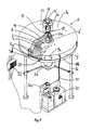
- the device according to the invention shown in FIG. 1 with the filling container omitted has an essentially rotationally symmetrical pickling chamber 1 with a bottom wall 2 sloping from the outer periphery to a central outlet opening 3, a top wall 4 sloping concentrically above it and a wall 4a between the outer wall and the bottom wall 2 formed annular inlet slot 5 for the seed.
- An outlet connection 3 a communicating with the outlet opening 3 is arranged below the bottom wall 2.
- annular guide tag 5a protrudes axially downward, on the lower edge of which an elastic annular guide strip 5b is arranged such that it extends axially downward to the bottom wall 2.
- the guide bar 5a and guide strip 5b serve to transfer the seed moved on the outer surface of the upper wall 4 towards the outer edge 4a onto the inner surface of the bottom wall 2.
- the pickling chamber 1 is accommodated in a housing 8, with the upper part 8a and a lower part 8b of the housing 8 an annular web 9 with access to the pickling chamber 1 the closable inspection opening 9a is provided.
- the ring web 9 can be designed as an elastic end strip, in which case the upper part 8a and lower part 8b of the housing 8 can be held together by suitable connecting elements and the inspection opening 9a can be missing.
- the housing 8 stands on stands 8c which are connected to the lower part 8b and can be screwed to the floor.
- a spraying device 6 for spraying the seed moved to the outlet opening 3 during operation on the inner surface of the bottom wall 2 is arranged in the dressing chamber 1.
- liquid pickling agent is supplied by a pump 30a from a storage container 30 via a hose 31 and a feed line 31a leading through the pickling chamber 1 to the spraying device 6.
- a switching device 32 serves to supply power and control the operation of the pump 30 a and the spray device 6.
- FIGS. 1 to 3 Details of the devices for regulating the seed supply are described below with reference to FIGS. 1 to 3.
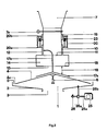
- a cylindrical downpipe 10 with a mouth opening 11 formed from the lower end of the closed downpipe wall and concentric with the top wall 4 of the pickling chamber 1.
- the downpipe 10 has a constant clear width of 90 mm.
- a metering nozzle 12 enclosing the lower portion thereof is axially displaceably guided with an outlet opening 13 lying coaxially in front of the opening 11 of the downpipe 10.
- the diameter of the outlet opening 13 of the metering nozzle 12 corresponds exactly to the diameter of the outlet opening 11 of the downpipe 10, in the embodiment shown in FIG. 3 it is slightly larger.
- the dosing nozzle 12 has at its lower end section a coaxial ring bulge 14 of constant cross-section with a radially inwardly inclined annular collecting surface 15 forming its underside.
- the collecting surface 15 forms the edge of the outlet opening 13 of the metering nozzle 12.
- the baffle surface 17 transfers the seed onto the top wall 4 of the seed chamber 1.
- a support ring 19 coaxially surrounds the downpipe 10 and is displaceable and lockable thereon.
- the support ring 19 serves as a support structure for energy storage devices 16, with one end 20a on the metering nozzle 12 and the other end 20b on the support ring 19 acting spring devices 20, oscillating movements of the metering nozzle 12 connected via the spring devices 20 to the support ring 19 by and with this damping devices 23 connected to support ring 19 are damped.
- the adjusting devices for changing the position of the support ring 19 on the downpipe 10 comprise an adjusting rack 22 which is fixedly connected to the supporting ring 19 and is in permanent engagement with an adjusting screw 21 which is mounted at 24 on the downpipe 10 and can be rotated via an actuating handle 21a and thereby into the adjusting rack 22 engagingly moves the support ring 19 coaxially on the downpipe 10.
- the width of the annular gap 18 between the edge of the outlet opening 13 and the baffle surface 17 can be adjusted on a scale 34 in the rest position of the metering nozzle 12.
- the annular gap 18 is adjusted by appropriate displacement of the support ring 19 so that the passage cross section of the annular gap 18 is smaller than the cross section of the outlet opening 13.
- the energy storage devices 16 and the weight of the metering nozzle 12 are designed so that the metering nozzle 12 in operation the width of the Annular gap 18 regulates itself automatically under the influence of the seed weight in the ring bulge 14, as will be described in more detail later.
- the dosing nozzle 12 actuates a switch 33 in its rest position, which stops the pump 30a, so that a dressing agent supply to the spraying device 6 takes place only when the dosing nozzle 12 is deflected from its rest position by seeds flowing into the dressing chamber 1.
- the width of the annular gap 18 in the rest position is detected by a regulating device 35 which interacts with the actuating devices 21, 22 and which enables a corresponding regulation of the supply of pickling liquid to the spraying device 6 by appropriate adjustment of the pump output.
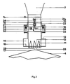
- the seed flows, optionally after opening a gate valve 7a arranged above the devices for regulating the seed supply in the downpipe, from the filling container 7 through the downpipe 10, some of which reaches the collecting surface 15 of the ring bulge 14 and through the impact and its weight deflects the metering nozzle 12 against the action of the spring devices 20 in the direction of the baffle 17.
- the ring bulge 14 fills even more with seed and briefly reaches the impact surface 17 with the ring gap 18 largely closed.
- the metering nozzle is raised again from the baffle 17 under the action of the spring devices 20 to such an extent that seed can flow through the annular gap 18.
- the size of the annular gap 18 that arises during operation is determined by the specific weight of the seed loaded in the annular bulge 14 and by an additional contribution to friction, which depends on the interaction between those fixed in the annular bulge 14 and on comes from these flowing seeds. Dynamic flow fluctuations in the downpipe 10 are compensated for by corresponding small axial movements of the metering nozzle 12.
- the seed flows over the baffle 17, which can be formed by the central region of the opening-free upper wall 4 of the seed chamber 1 (FIGS. 1 and 3), alternatively it is also possible, for example, as shown in FIG.
- baffle part 17a which is fastened to a holding rod 17b which is fixedly connected to the downpipe 10.
- a baffle part 17a can be used which has a shape different from the top wall 4 of the pickling chamber 1.
- The. Seed flows over the top wall 4 of the dressing chamber 1, which has the shape of a conical jacket with an outward slope of approximately 20 degrees, which leads the seed to the outer edge, and passes through the inlet slot 5 onto the inner surface of the bottom wall 2.
- This is as shown in the figure 2 shows, connected via connecting rods 26b to a ball bearing 26a, through which the drive shaft 25a of a motor 25 is guided.
- the drive shaft 25a On the side of the ball bearing 26a facing away from the motor 25, the drive shaft 25a carries a clamp 26 serving as an unbalance element, which surrounds the drive shaft 25a and projects radially from it on one side.
- the drive shaft 25a rotates at 2,500 to 3,000 rpm; the vibrations caused by the unbalance element 26 are transmitted via the connecting rods 26b to the bottom wall 2 and possibly also to the top wall 4 of the pickling chamber 1 and produce an essentially vertically directed vibration. Since the pickling chamber 1 is supported so that it can vibrate via the elastic buffer part 27 and the motor 25 is also resiliently attached to vibrating metals, the strong vibration which arises does not damage the device.
- the bottom wall 2 is only inclined at an angle of seven degrees to the horizontal, so that the seed would not be moved essentially towards the outlet opening 3 without vibration. Due to the vibration of the bottom wall 2, however, the seed is conveyed from the inlet slit 5 via the bottom wall 2 to the outlet opening 3 while continuously throwing up and turning. It is wetted on all sides by the spray device 6 with dressing liquid, the supply of dressing liquid to the spray device 6 being regulated via the control device 35 exactly in accordance with the weight of the seed flowing through the device. The seeded seed leaves the device through the outlet opening 3 and the outlet nozzle 3a.
- Tests were carried out with the devices shown in FIGS. 1 and 2, in each of which tests for the flow of 25 kg of wheat. Oats, rye and barley required times were measured depending on the setting of the support ring 19 and thus on the presetting of the width of the annular gap 18 in the rest position of the metering nozzle 12.
- the width of the annular gap 18 in the rest position in the device according to FIG. 1 was 4.2 cm for the greatest flow value of about 10 tons of seed per hour and 2 cm for a throughput of about 4 tons of seed per hour.
- the amount of seed weight flowing through the device per unit of time was the same for all four seed types within an error limit of approx. 5 percent, although the different seed types had up to 40 percent different specific weights.
- the delivery rate of the pump 30a for the pickling liquid is coupled via the regulating devices 24 to the adjusting devices for the relative position of the support ring 19, so it is necessary that the adjustment steps of the support ring 19 simply cause proportional changes in the pickling liquid supply.
- the downpipe 10 protrudes axially projecting wall segments 28 at the mouth opening 11 has, which protrude in the rest position of the metering nozzle 12 through its outlet opening 13 in the direction of the baffle 17.
- the wall openings 29 lying between the wall segments 28 are essentially diamond-shaped.
- the metering nozzle 12 is compared to the downpipe 10 in for small throughput presets the rest position is set so close to the baffle surface 17 that its outlet opening is below the wall segments 28. The mode of operation then corresponds completely to the embodiments already described with reference to FIGS. 1 and 2.
- the metering nozzle is removed from the impact surface 17 by adjusting the support ring 19 so far that its outlet opening 13 encloses the side wall openings 29 between the wall segments 28 in the rest position.
- the metering nozzle 12 is deflected in the manner mentioned in the direction of the baffle surface 17 and the ring bulge 14 is filled with seed. While the seed subsequently flows through the device, the outlet opening 13 of the metering nozzle 12 then moves at high throughputs in the area of the axial extension of the wall segments 28.
- the annular gap 18 is thus changed in its width and geometry by the above wall segment areas, which ensures the compensation of the not strictly linear relationship between the annular gap width and the flow rate at high throughputs.
- the wall segments 28 carry an inwardly projecting, annular web-like baffle that connects them to one another.
- the baffle has a central opening of approximately half the diameter of the mouth opening 11 of the downpipe 10 and is inclined radially outwards in a cone-like manner so that seeds can slide radially outwards through the wall openings 29.
- a ridge-like baffle surface it is also possible, for example, to provide individual wall segments 28 with inwardly projecting baffle surfaces.
Priority Applications (1)
| Application Number | Priority Date | Filing Date | Title |
|---|---|---|---|
| AT85100400T ATE50901T1 (de) | 1984-01-30 | 1985-01-16 | Vorrichtung zum feuchtbeizen von saatgut. |
Applications Claiming Priority (2)
| Application Number | Priority Date | Filing Date | Title |
|---|---|---|---|
| DE19843403069 DE3403069A1 (de) | 1984-01-30 | 1984-01-30 | Vorrichtung zum feuchtbeizen von saatgut |
| DE3403069 | 1984-01-30 |
Publications (3)
| Publication Number | Publication Date |
|---|---|
| EP0150766A2 EP0150766A2 (de) | 1985-08-07 |
| EP0150766A3 EP0150766A3 (en) | 1986-08-13 |
| EP0150766B1 true EP0150766B1 (de) | 1990-03-14 |
Family
ID=6226238
Family Applications (1)
| Application Number | Title | Priority Date | Filing Date |
|---|---|---|---|
| EP85100400A Expired - Lifetime EP0150766B1 (de) | 1984-01-30 | 1985-01-16 | Vorrichtung zum Feuchtbeizen von Saatgut |
Country Status (6)
| Country | Link |
|---|---|
| EP (1) | EP0150766B1 (un) |
| AT (1) | ATE50901T1 (un) |
| CA (1) | CA1228339A (un) |
| DE (2) | DE3403069A1 (un) |
| DK (1) | DK59984A (un) |
| SU (1) | SU1409115A3 (un) |
Families Citing this family (2)
| Publication number | Priority date | Publication date | Assignee | Title |
|---|---|---|---|---|
| FR2593663B1 (fr) * | 1986-01-31 | 1989-04-14 | Sip Condi Film Sa | Procede de regulation de traitement de graines et de produits similaires, moyens pour la mise en oeuvre de ce procede et installations de traitement pourvues de ces moyens |
| CN106455483A (zh) * | 2014-05-12 | 2017-02-22 | 拜耳农作物科学股份公司 | 在拌种操作过程中设定播种材料的特定干燥度的方法和装置 |
Family Cites Families (5)
| Publication number | Priority date | Publication date | Assignee | Title |
|---|---|---|---|---|
| US3155542A (en) * | 1960-09-22 | 1964-11-03 | Ben Gustason & Son Mfg Company | Cottonseed-treating machine |
| DE1211013B (de) * | 1960-11-28 | 1966-02-17 | Ben Gustafson & Son Mfg Co | Vorrichtung zum Beizen von Saatgut, insbesondere nicht vollstaendig entlinterten Baumwollsamens |
| US3213867A (en) * | 1962-11-21 | 1965-10-26 | Mcintyre William John | Seed treatment machine |
| FR2302142A1 (fr) * | 1975-02-28 | 1976-09-24 | Bp Chem Int Ltd | Appareil pour l'application de liquides a des solides granulaires |
| SU665835A1 (ru) * | 1976-06-17 | 1979-06-05 | Всесоюзный Ордена Трудового Красного Знамени Научно-Исследовательский Институт Сельскохозяйственного Машиностроения Им. В.П.Горячкина | Протравливатель сем н |
-
1984
- 1984-01-30 DE DE19843403069 patent/DE3403069A1/de active Granted
- 1984-02-10 DK DK59984A patent/DK59984A/da not_active Application Discontinuation
-
1985
- 1985-01-16 EP EP85100400A patent/EP0150766B1/de not_active Expired - Lifetime
- 1985-01-16 AT AT85100400T patent/ATE50901T1/de not_active IP Right Cessation
- 1985-01-16 DE DE8585100400T patent/DE3576450D1/de not_active Expired - Lifetime
- 1985-01-29 SU SU853862714A patent/SU1409115A3/ru active
- 1985-01-29 CA CA000473022A patent/CA1228339A/en not_active Expired
Also Published As
| Publication number | Publication date |
|---|---|
| DK59984D0 (da) | 1984-02-10 |
| EP0150766A3 (en) | 1986-08-13 |
| DK59984A (da) | 1985-07-31 |
| DE3403069A1 (de) | 1985-08-08 |
| EP0150766A2 (de) | 1985-08-07 |
| DE3403069C2 (un) | 1987-10-08 |
| DE3576450D1 (de) | 1990-04-19 |
| ATE50901T1 (de) | 1990-03-15 |
| SU1409115A3 (ru) | 1988-07-07 |
| CA1228339A (en) | 1987-10-20 |
Similar Documents
| Publication | Publication Date | Title |
|---|---|---|
| EP0466857B2 (de) | Vorrichtung, verfahren und anwendung des verfahrens zum erfassen eines produktionsstromes | |
| DE2706627C3 (de) | Vorrichtung zum Messen der Fließgeschwindigkeit von pulvrigem und/oder körnigem Material | |
| DE3536347A1 (de) | Verfahren und vorrichtung zur automatischen erfassung des durchsatzes eines schuettgutstromes, z.b. getreide | |
| EP0432190B1 (de) | Zuführvorrichtung für schüttgut bei einer massendurchsatzwiegeeinrichtung | |
| EP0509957B1 (de) | Vorrichtung zum dosierten Zuführen von Pulver zu einer Pulververarbeitungseinheit | |
| EP0150766B1 (de) | Vorrichtung zum Feuchtbeizen von Saatgut | |
| DE102006061818B4 (de) | Austragsvorrichtung für pulver- oder granulatförmige Feststoffe von Dünger- bzw. Tierfutter-Dosier-Mischanlagen sowie Verfahren zum Betreiben einer solchen Vorrichtung | |
| DE4026957A1 (de) | Zufuehrvorrichtung fuer das einem extruder in mehreren komponenten zuzufuehrende, zu extrudierende material | |
| DE10130808C2 (de) | Probenteiler | |
| DE3715381A1 (de) | Verteilvorrichtung | |
| DD251623A1 (de) | Verfahren und vorrichtung zur kontinuierlichen glaettung eines gutstromes von rieselfaehigem, pulverfoermigem bis koernigem gut | |
| DE8402542U1 (de) | Vorrichtung zum feuchtbeizen von saatgut | |
| EP0121599A2 (de) | Verfahren und Vorrichtung zur pneumatischen Förderung von Feingut | |
| EP0222695A1 (de) | Dosiervorrichtung | |
| DE19743481A1 (de) | Vorrichtung zum Fördern und Mischen von Schüttgut | |
| DE102018113852B4 (de) | Labor-Dosiervorrichtung | |
| CH697750A2 (de) | Materialhandhabevorrichtung. | |
| CH691466A5 (de) | Abfüllkopf für Vertikal-Dosierer. | |
| DE3233151C2 (de) | Mischvorrichtung, insbesondere für die Betonindustrie | |
| DE19960901A1 (de) | Dosiervorrichtung für eine Getreidemühle | |
| EP0309641A2 (de) | Vorrichtung zur Entnahme und Teilung von Proben | |
| AT405979B (de) | Dosiereinheit, insbesondere für zu dosierende abrasive | |
| DE4319014A1 (de) | Zyklonabscheider | |
| EP0603701A1 (de) | Vorrichtung zum streifen- oder tropfenförmigen Ausbringen fliessfähiger Massen | |
| DE7401804U (de) | Dosiervorrichtung für staubförmiges Material |
Legal Events
| Date | Code | Title | Description |
|---|---|---|---|
| PUAI | Public reference made under article 153(3) epc to a published international application that has entered the european phase |
Free format text: ORIGINAL CODE: 0009012 |
|
| AK | Designated contracting states |
Kind code of ref document: A2 Designated state(s): AT BE CH DE FR GB IT LI LU NL SE |
|
| PUAL | Search report despatched |
Free format text: ORIGINAL CODE: 0009013 |
|
| AK | Designated contracting states |
Kind code of ref document: A3 Designated state(s): AT BE CH DE FR GB IT LI LU NL SE |
|
| 17P | Request for examination filed |
Effective date: 19870205 |
|
| 17Q | First examination report despatched |
Effective date: 19881011 |
|
| GRAA | (expected) grant |
Free format text: ORIGINAL CODE: 0009210 |
|
| AK | Designated contracting states |
Kind code of ref document: B1 Designated state(s): AT BE CH DE FR GB IT LI LU NL SE |
|
| PG25 | Lapsed in a contracting state [announced via postgrant information from national office to epo] |
Ref country code: SE Effective date: 19900314 Ref country code: NL Effective date: 19900314 Ref country code: IT Free format text: LAPSE BECAUSE OF FAILURE TO SUBMIT A TRANSLATION OF THE DESCRIPTION OR TO PAY THE FEE WITHIN THE PRESCRIBED TIME-LIMIT;WARNING: LAPSES OF ITALIAN PATENTS WITH EFFECTIVE DATE BEFORE 2007 MAY HAVE OCCURRED AT ANY TIME BEFORE 2007. THE CORRECT EFFECTIVE DATE MAY BE DIFFERENT FROM THE ONE RECORDED. Effective date: 19900314 Ref country code: BE Effective date: 19900314 |
|
| REF | Corresponds to: |
Ref document number: 50901 Country of ref document: AT Date of ref document: 19900315 Kind code of ref document: T |
|
| REF | Corresponds to: |
Ref document number: 3576450 Country of ref document: DE Date of ref document: 19900419 |
|
| ET | Fr: translation filed | ||
| GBT | Gb: translation of ep patent filed (gb section 77(6)(a)/1977) | ||
| NLV1 | Nl: lapsed or annulled due to failure to fulfill the requirements of art. 29p and 29m of the patents act | ||
| PLBE | No opposition filed within time limit |
Free format text: ORIGINAL CODE: 0009261 |
|
| STAA | Information on the status of an ep patent application or granted ep patent |
Free format text: STATUS: NO OPPOSITION FILED WITHIN TIME LIMIT |
|
| PGFP | Annual fee paid to national office [announced via postgrant information from national office to epo] |
Ref country code: GB Payment date: 19910109 Year of fee payment: 7 |
|
| PG25 | Lapsed in a contracting state [announced via postgrant information from national office to epo] |
Ref country code: AT Effective date: 19910116 |
|
| PG25 | Lapsed in a contracting state [announced via postgrant information from national office to epo] |
Ref country code: LU Free format text: LAPSE BECAUSE OF NON-PAYMENT OF DUE FEES Effective date: 19910131 Ref country code: LI Effective date: 19910131 Ref country code: CH Effective date: 19910131 |
|
| 26N | No opposition filed | ||
| REG | Reference to a national code |
Ref country code: CH Ref legal event code: PL |
|
| PG25 | Lapsed in a contracting state [announced via postgrant information from national office to epo] |
Ref country code: GB Effective date: 19920116 |
|
| GBPC | Gb: european patent ceased through non-payment of renewal fee | ||
| PGFP | Annual fee paid to national office [announced via postgrant information from national office to epo] |
Ref country code: FR Payment date: 19921229 Year of fee payment: 9 |
|
| PG25 | Lapsed in a contracting state [announced via postgrant information from national office to epo] |
Ref country code: FR Effective date: 19940930 |
|
| REG | Reference to a national code |
Ref country code: FR Ref legal event code: ST |
|
| PGFP | Annual fee paid to national office [announced via postgrant information from national office to epo] |
Ref country code: DE Payment date: 19950217 Year of fee payment: 11 |
|
| PG25 | Lapsed in a contracting state [announced via postgrant information from national office to epo] |
Ref country code: DE Effective date: 19961001 |