EP0150766B1 - Humid seed dressing - Google Patents
Humid seed dressing Download PDFInfo
- Publication number
- EP0150766B1 EP0150766B1 EP85100400A EP85100400A EP0150766B1 EP 0150766 B1 EP0150766 B1 EP 0150766B1 EP 85100400 A EP85100400 A EP 85100400A EP 85100400 A EP85100400 A EP 85100400A EP 0150766 B1 EP0150766 B1 EP 0150766B1
- Authority
- EP
- European Patent Office
- Prior art keywords
- outlet opening
- dressing
- seed
- metering socket
- chamber
- Prior art date
- Legal status (The legal status is an assumption and is not a legal conclusion. Google has not performed a legal analysis and makes no representation as to the accuracy of the status listed.)
- Expired - Lifetime
Links
Images
Classifications
-
- A—HUMAN NECESSITIES
- A01—AGRICULTURE; FORESTRY; ANIMAL HUSBANDRY; HUNTING; TRAPPING; FISHING
- A01C—PLANTING; SOWING; FERTILISING
- A01C1/00—Apparatus, or methods of use thereof, for testing or treating seed, roots, or the like, prior to sowing or planting
- A01C1/08—Immunising seed
Landscapes
- Life Sciences & Earth Sciences (AREA)
- Soil Sciences (AREA)
- Environmental Sciences (AREA)
- Pretreatment Of Seeds And Plants (AREA)
- Enzymes And Modification Thereof (AREA)
- Preparation Of Compounds By Using Micro-Organisms (AREA)
- Crystals, And After-Treatments Of Crystals (AREA)
- Transition And Organic Metals Composition Catalysts For Addition Polymerization (AREA)
- Materials For Medical Uses (AREA)
- Sowing (AREA)
Abstract
Description
Die Erfindung betrifft eine Vorrichtung zum Feuchtbeizen von Saatgut, insbesondere Getreide, mit einer im wesentlichen rotationssymetrischen Beizkammer mit vom Außenumfang zu einer zentrischen Austrittsöffnung geneigt abfallender Bodenwand, einer konzentrisch darüber angeordneten, auswärts geneigt abfallenden Oberwand und einem zwischen deren Außenrand und der Bodenwand gebildeten ringförmigen Einlaßschlitzfür das Saatgut, mindestens einer in der Beizkammer angeordneten Sprühvorrichtung zum Besprühen des im Betrieb auf der Innenfläche der Bodenwand zur Austrittsöffnung bewegten Saatguts, einem über der Beizkammer angeordneten, das zu beizende Saatgut aufnehmenden Füllbehälter mit einer über der Oberwand konzentrisch angeordneten Durchflußöffnung, Vorrichtungen zur dosierten Zuführung von Beizflussigkeit zu jeder Sprühvorrichtung sowie Vorrichtungen zur Regelung der Saatgutzuführ.The invention relates to a device for wet dressing of seeds, in particular grain, with a substantially rotationally symmetrical pickling chamber with a bottom wall sloping from the outer circumference to a central outlet opening, a concentrically arranged top wall sloping outwards and an annular inlet slot formed between the outer edge and the bottom wall the seeds, at least one spray device arranged in the seed chamber for spraying the seed moved during operation on the inner surface of the bottom wall to the outlet opening, a filling container arranged above the seed chamber and receiving the seed to be seeded with a flow opening arranged concentrically above the top wall, devices for metered feeding of liquidity to each spraying device and devices for regulating the seed supply.
Die in der deutschen Schrift DE-B-1 211 013 beschriebene Vorrichtung dieser Art weist einen unmittelbar unterhalb der Austrittsöffnung eines Vorratsbehälters angeordneten, das Sattgut in einen Schleier auflössenden Streukegel und eine unter diesem axial angeordnete Schleuderscheibe für das Vernebeln des Beizmaterials auf, wobei der Steukegel in Drehbewegung versetzbar ist und über dem Streukegel, koaxial zu diesem und mit ihm umlaufend eine in den Vorratsbehälter hineinragende Förderschnecke angeordnet ist. Die Auslaßöffnung des Vorratsbehälters ist von einem Kragenteil umgeben, daß gegenüber der Oberfläche des Streukegels in einem bestimmten Abstand-entsprechend dem zu behandelnden Saatgut-einstellbar ist. Die Einstellung des Kragenteils erfolgt über eine Handkurbel mit Gewindespindel und Hebelgestänge.The device of this type described in German document DE-B-1 211 013 has a scatter cone which is arranged directly below the outlet opening of a storage container and dissolves the seed material in a veil, and a centrifugal disc arranged axially below this for atomizing the pickling material, the control cone is rotatable and is arranged above the scattering cone, coaxially with it and all around it, a screw conveyor projecting into the storage container. The outlet opening of the storage container is surrounded by a collar part that is adjustable at a certain distance from the surface of the scattering cone, corresponding to the seed to be treated. The collar part is adjusted using a hand crank with threaded spindle and lever linkage.
Die einer bestimmten Saatgutmenge zuzuführende Beizmittelmenge ist gewichtsmäßig innerhalb enger Grenzen gesetzlich festgelegt; das Beizmittel muß möglichst gleichmäßig und allseitig auf die Saatgutkörner aufgebracht werden. Das Kragenteil der bekannten Vorrichtung kann einen hinreichend gewichtskonstanten Saatgutfluß durch die Vorrichtung nicht gewährleisten, so daß es zu erheblichen Schwankungen der Mengenverhältnisse von Saatgut und Beizmittel kommt. Eine exakte Voreinstellung der Durchflußmengen für verschiedene Saatgutarten und unterschiedliche Durchsätze ist praktisch nicht möglich. Zur Auflösung das zugeführten Saatgutes in einen schleierartigen Saatgutstrom sind aufwendige mechanische Teile erforderlich, die leicht Anlaß von Betriebsstörungen sein können.The amount of seed dressing to be supplied to a certain amount of seed is legally determined by weight within narrow limits; the seed dressing must be applied to the seed grains as evenly as possible on all sides. The collar part of the known device cannot ensure a sufficiently constant weight flow of seeds through the device, so that there are considerable fluctuations in the quantity ratios of seed and dressing agent. An exact presetting of the flow rates for different types of seeds and different throughputs is practically impossible. In order to dissolve the supplied seed in a veil-like seed stream, complex mechanical parts are required, which can easily cause malfunctions.
Aufgabe der Erfindung ist es daher, eine einfache und unaufwendige Vorrichtung zum Feuchtbeizen von Saatgut der eingangs genannten Art zu schaffen, die ein schnelles gleichmaßiges Aufbringen der Beizflüssigkeit auf das Saatgut unter genauer Einhaltung und Reproduzierbarkeit vorbestimmter Gewichtsverhältnisse gestattet.The object of the invention is therefore to provide a simple and uncomplicated device for the wet dressing of seeds of the type mentioned at the outset, which allows a rapid, uniform application of the dressing liquid to the seeds with exact adherence and reproducibility of predetermined weight ratios.
Zur Lösung dieser Aufgabe ist die Vorrichtung der eingangs genannten Art erfindungsgemäß mit den im kennzeichnenden Teil des Anspruchs 1 angegebenen Merkmalen ausgestattet.To achieve this object, the device of the type mentioned is equipped according to the invention with the features specified in the characterizing part of claim 1.
Die Erfindung bewirkt eine Zuführung des Saatgutes in gleichbleibenden Gewichtsanteilen zur Beizkammer, wobei Unterschiede in Form, Feuchtigkeit, Oberflächeneigenschaften, spezifischem Gewicht usw, zwischen verschiedenen Saatgutchargen bzw, -arten und Schwankungen in der vom Füllbehälter nachfließenden Saatgutmenge automatisch ausgeglichen werden. Dadurch ist die genaue Einhaltung und Reproduzierbarkeit der vorgegebenen Gewichtsverhältnisse in einfacher und unaufwendiger Weise gewährleistet.The invention causes the seeds to be fed in constant weight fractions to the seed chamber, differences in shape, moisture, surface properties, specific weight, etc., between different seed batches or types and fluctuations in the seed quantity flowing in from the hopper being automatically compensated for. This ensures exact compliance and reproducibility of the specified weight ratios in a simple and uncomplicated manner.
Vorteilhafte weitere Ausgestaltungen sind in den Unteransprüchen 2 bis 12 beschrieben.Advantageous further developments are described in
Die Verstellbarkeit der Breite des Ringspalts in der Ruhestellung des Dosierstutzens erlaubt eine zuverlässige Vorwahl des Saatgut-Durchsatzes pro Zeiteinheit. Diese Voreinstellung wird zur entsprechenden Regelung der Zuführung von Beizflüssigkeit erfaßt. Des Saatgut wird unter Besprühen auf der Innenfläche der Bodenwand zur Austrittsöffnung bewegt und dabei durch die vertikale Vibration der Bodenwand fortwährend hochgeworfen. Dadurch wird das Saatgut gleichmäßiger allseitig von Beizflüssigkeit benetzt als bisher.The adjustability of the width of the annular gap in the rest position of the metering nozzle allows reliable preselection of the seed throughput per unit of time. This presetting is recorded for the corresponding regulation of the supply of pickling liquid. The seed is sprayed onto the inside surface of the bottom wall and moved to the outlet opening, being continuously thrown up by the vertical vibration of the bottom wall. As a result, the seed is wetted more uniformly on all sides by dressing liquid than before.
Im folgenden werden bevorzugte Ausführungsformen der Vorrichtung auhand der beigefügten Zeichnungen weiter erläutert.In the following preferred embodiments of the device are further explained with reference to the attached drawings.
Es zeigen:
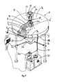
- Fig. 1 einen perspektivischen Teilschnitt der Vorrichtung ohne den Füllbehälter;
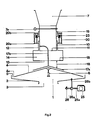
- Fig. 2 einen schematischen Teilschnitt einer bevorzugten Ausführungsform der Vorrichtung und
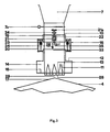
- Fig. 3 eine schematische Darstellung einer abgewandelten Vorrichtung.
- Figure 1 is a partial perspective section of the device without the filling container.
- Fig. 2 is a schematic partial section of a preferred embodiment of the device and
- Fig. 3 is a schematic representation of a modified device.
Die in Fig. 1 unter Fortlassung des Füllbehälters dargestellte erfindungsgemäße Vorrichtung weist eine im wesentlichen rotationssymmetrische Beizkammer 1 mit vom Außenumfang zu einer zentrischen Austrittsöffnung 3 geneigt abfallender Bodenwand 2, einer konzentrisch darüber angeordneten auswärts geneigt abfallenden Oberwand 4 und einem zwischen deren Außenwand 4a und der Bodenwand 2 gebildeten ringförmigen Einlaßschlitz 5 für das Saatgut auf. Ein mit der Austrittsöffnung 3 kommunizierender Austrittsstutzen 3a ist unterhalb der Bodenwand 2 angeordnet.The device according to the invention shown in FIG. 1 with the filling container omitted has an essentially rotationally symmetrical pickling chamber 1 with a
Am Außenumfang eines Gehäuse-Oberteils 8a steht ein ringförmiger Leitstag 5a axial abwärts vor, an dessen Unterkante ein elastischer ringförmiger Leitstreifen 5b so angeordnet ist, daß er sich axial abwärts bis zur Bodenwand 2 erstreckt. Leitsteg 5a und Leitstreifen 5b dienen zum Überführen des auf der Außenfläche der Oberwand 4 zum Außenrand 4a hin bewegten Saatgutes auf die Innenfläche der Bodenwand 2. Die Beizkammer 1 ist in einem Gehäuse 8 aufgenommen, wobei zwischen dem Oberteil 8a und einem Unterteil 8b des Gehäuses 8 ein Ringsteg 9 mit einer den Zutritt zur Beizkammer 1 ermöglichenden, verschließbaren Inspektionsöffnung 9a vorgesehen ist. Alternativ dazu kann der Ringsteg 9 als elastischer Abschlußstreifen ausgeführt werden, wobei dann Oberteil 8a und Unterteil 8b des Gehäuses 8 durch geeignete Verbindungselemente zusammengehalten werden und die Inspektionsöffnung 9a fehlen kann.On the outer circumference of an upper housing part 8a, an
Das Gehäuse 8 steht auf mit dem Unterteil 8b verbundenen Ständern 8c, die am Fußboden verschraubt werden können. Auf der Innenseite des Gehäuse-Unterteils 8b liegt nahe dessen Umfangskante ein ringförmiges elastisches Pufferteil 27, auf dem die Bodenwand 2 der Beizkammer 1 gelagert ist.The housing 8 stands on stands 8c which are connected to the lower part 8b and can be screwed to the floor. On the inside of the lower housing part 8b there is an annular
In der Beizkammer 1 ist eine Spruhvorrichtung 6 zum Besprühen des im Betrieb auf der Innenfläche der Bodenwand 2 zur Austrittsöffnung 3 bewegten Saatguts angeordnet. Im Betrieb wird flüssiges Beizmittel von einer Pumpe 30a aus einem Vorratsbehälter 30 über einen Schlauch 31 und eine durch die Beizkammer 1 zur Sprühvorrichtung 6 führenden Zuführleitung 31a zugeführt. Eine Schaltvorrichtung 32 dient zur Stromversorgung und Betriebsregelung der Pumpe 30a und der Sprühvorrichtung 6.A
Im folgenden werden Einzelheiten der Vorrichtungen zur Regelung der Saatgutzufuhr anhand der Figuren 1 bis 3 beschrieben. An der Unterseite des Füllbehälters 7 ist ein zylindrisches Fallrohr 10 mit einer vom unteren Ende der geschlossenen Fallrohrwand gebildeten, zur Oberwand 4 der Beizkammer 1 konzentrischen Mündungsöffnung 11 angeordnet. Das Fallrohr 10 weist eine konstante lichte Weite von 90 mm auf. Auf dem Fallrohr 10 ist ein dessen unteren Abschnitt umschließender Dosierstutzen 12 mit einer koaxial vor der Mündungsöffnung 11 des Fallrohres 10 liegenden Auslaßöffnung 13 axial verschiebbar geführt. Der Durchmesser der Auslaßöffnung 13 des Dosierstutzens 12 entspricht bei den in den Figuren 1 und 2 gezeigten Ausführungsformen genau dem Durchmesser der Mündungsöffnung 11 des Fallrohres 10, bei der in Figur 3 gezeigten Ausführungsform ist er geringfügig größer.Details of the devices for regulating the seed supply are described below with reference to FIGS. 1 to 3. On the underside of the
Der Dosierstutzen 12 weist an seinem unteren Endabschnitt eine koaxiale Ringausbauchung 14 gleichbleibenden Querschnitts mit einer deren Unterseite bildenden, radial einwärts geneigten ringförmigen Auffangfläche 15 auf. Die Auffangfläche 15 bildet den Rand der Auslaßöffnung 13 des Dosierstutzens 12. Unter der.Auslaßöffnung 13 des Dosierstutzens 12 ist eine zu diesem konzentrische Prallfläche 17 angeordnet, die vom Mittelbereich der öffnungslosen Oberwand 4 der Beizkammer 1 gebildet wird. Die Prallfläche 17 leitet das Saatgut auf die Oberwand 4 der Beizkammer 1 über.The
Ein Tragring 19 umgibt koaxial das Fallrohr 10 und ist an diesem verschiebbar und feststellbar. Der Tragring 19 dient sie Tragstruktur für Kraftspeichervorrichtungen 16 bildende, mit einem Ende 20a am Dosierstutzen 12 und mit dem anderen Ende 20b am Tragring 19 angreifende Federvorrichtungen 20, Schwingungsbewegungen des über die Federvorrichtungen 20 mit dem Tragring 19 verbundenen Dosierstutzens 12 werden durch mit diesem und mit dem Tragring 19 verbundene Dämpfvorrichtungen 23 gedämpft. Die Stellvorrichtungen zur Änderung der Position des Trägrings 19 auf dem Fallrohr 10 umfassen eine fest mit dem Tragring 19 verbundene Stellzahnstange 22 im dauernden Eingriff mit einer Stellschnecke 21, die bei 24 am Fallrohr 10 gelagert und über einen Betätigungsgriff 21a verdrehbar ist und dabei in die Stellzahnstange 22 eingreifend den Tragring 19 koaxial am Fallrohr 10 verschiebt. Durch diese Verschiebung ist an einer Skala 34 die Breite des Ringspalts 18 zwischen dem Rand der Auslaßöffnung 13 und der Prallfläche 17 in der Ruhestellung des Dosierstutzens 12 einstellbar. Der Ringspalt 18 wird durch entsprechende Verschiebung des Tragringes 19 so eingestellt, daß der Durchlaßquerschnitt des Ringspalts 18 kleiner ist als der Querschnitt der Auslaßöffnung 13. Die Kraftspeichervorrichtungen 16 und das Gewicht des Dosierstutzens 12 sind so ausgelegt, daß der Dosierstutzen 12 im Betrieb die Breite des Ringspaltes 18 jeweils unter dem Einfluß des in der Ringausbauchung 14 lastenden Saatgutgewichts selbsttätig regelt, wie später noch eingehender beschrieben wird. Der Dosierstutzen 12 betätigt in seiner Ruhestellung einen Abschalter 33, der die Pumpe 30a stillsetzt, so daß eine Beizmittel-Zuführung zur Sprühvorrichtung 6 nur erfolgt, wenn der Dosierstutzen 12 durch in die Beizkammer 1 fließendes Saatgut aus seiner Ruhestellung ausgelenkt wird.A
Die Breite des Ringspaltes 18 in der Ruhestellung wird durch eine mit den Stellvorrichtungen 21, 22 zusammenwirkende Regelvorrichtung 35 erfaßt, die eine entsprechende Regelung der Zuführung von Beizflüssigkeit zur Sprühvorrichtung 6 durch entsprechende Anpassung der Pumpenleistung ermöglicht.The width of the
Im Betrieb fließt das Saatgut, gegebenenfalls nach Öffnen eines oberhalb der Vorrichtungen zur Regelung der Saatgut-Zuführ im Fallrohr angeordneten Absperrschiebers 7a, vom Füllbehälter 7 durch das Fallrohr 10, wobei es zum Teil auf die Auffangfläche 15 der Ringausbauchung 14 gelangt und durch den Aufprall sowie sein Gewicht den Dosierstutzen 12 gegen die Wirkung der Federvorrichtungen 20 in Richtung auf die Prallfläche 17 hin auslenkt. Durch diese Auslenkung füllt sich die Ringausbauchung 14 noch mehr mit Saatgut und gelangt kurzzeitig unter weitgehender Schließung des Ringspaltes 18 dicht an die Prallfläche 17 heren. Nach vollständiger Füllung der Ringausbauchung 14 mit Saatgut wird der Dosierstutzen unter der Einwirkung der Federvorrichtungen 20 wieder soweit von der Prallfläche 17 weg angehoben, daß Saatgut durch den Ringspalt 18 abfließen kann. Die Größe des im Betrieb entstehenden Ringspaltes 18, der kleiner ist als in der Ruhestellung des Dosierstutzens 12, wird dabei durch das spezifiche Gewicht des in der Ringausbauchung 14 lastenden Saatguts und durch einen zusätzlichen Reibungsbeitrag bestimmt, der von der Wechselwirkung zwischen in der Ringausbauchung 14 festliegenden und an diesen vorbeifließenden Saatgutkörnern herrührt. Dynamische Strömungsschwankungen im Fallrohr 10 werden dabei durch entsprechende kleine axiale Bewegungen des Dosierstutzens 12 ausgeglichen. Nach Durchtritt durch den Ringspalt 18 fließt das Saatgut über die Prallfläche 17, die vom Mittenbereich der öffnungslosen Oberwand 4 der Beizkammer 1 gebildet sein kann (Figuren 1 und 3), alternativ ist es z.B. auch möglich, wie in Figur 2 gezeigte, eine von der Oberwand 4 der Beizkammer 1 getrennte Prallfläche in Form eines Prallteils 17a vorzusehen, das an einer fest mit dem Fallrohr 10 verbundenen Haltestange 17b befestigt ist. So kann zur Abänderung der Ringspaltgröße bzw. -geometrie ein Prallteil 17a verwendet werden, das eine von der Oberwand 4 der Beizkammer 1 verschiedene Form aufweist.In operation, the seed flows, optionally after opening a
Das. Saatgut fließt über die Oberwand 4 der Beizkammer 1, die die Form eines Kegelmantels mit einer auswärts abfallenden, das Saatgut zum Außenrand abführenden Neigung von ungefähr 20 Grad aufweist, und gelangt durch den Einlaßschlitz 5 auf die Innenfläche der Bodenwand 2. Diese ist, wie Figur 2 zeigt, über Verbindungsstangen 26b mit einem Kugellager 26a verbunden, durch das die Antriebswelle 25a eines Motors 25 passend geführt ist. Auf der vom Motor 25 abgewandten Seite des Kugellagers 26a trägt die Antriebswelle 25a eine als Unwuchtelement dienende Schelle 26, die die Antriebswelle 25a umschließt und einseitig radial von ihr absteht. Im Betrieb rotiert die Antriebswelle 25a mit 2.500 bis 3.000 UpM; die durch das Unwuchtelement 26 hervorgerufenen Schwingungen werden über die Verbindungsstangen 26b auf die Bodenwand 2 und gegebenenfalls auch auf die Oberwand 4 der Beizkammer 1 übertragen und erzeugen eine im wesentlichen vertikal gerichtete Vibration. Da die Beizkammer 1 über das elastische Pufferteil 27 vibrationsfähig gelagert ist und auch der Motor 25 an Schwingmetallen federnd befestigt ist, führt die entstehende starke Vibration nicht zur Beschädigung der Vorrichtung.The. Seed flows over the
Die Bodenwand 2 ist nur unter einem Winkel von sieben Grad gegen die Horizontale geneigt, so daß das Saatgut ohne Vibrationsbewegung im wesentlichen nicht zur Austrittsöffnung 3 hin bewegt würde. Durch die Vibration der Bodenwand 2 wird das Saatgut jedoch unter fortdauerndem Hochwerfen und Wenden vom Einlaßschlitz 5 über die Bodenwand 2 zur Austrittsöffnung 3 gefördert. Dabei wird es durch die Sprühvorrichtung 6 allseitig mit Beizflüssigkeit benetzt, wobei die Zuführung von Beizflüssigkeit zur Sprühvorrichtung 6 über die Regelvorrichtung 35 genau entsprecehend der Gewichtsmenge des durch die Vorrichtung fließenden Saatguts geregelt wird. Das gebeizte Saatgut verläßt die Vorrichtung durch die Austrittsöffnung 3 und den Austrittsstutzen 3a.The
Mit den in Figuren 1 und 2 gezeigten Vorrichtungen wurden jeweils Versuche durchegeführt, bei denen die jeweils zum Durchfluß von 25 kg Weizen. Hafer, Roggen und Gerste benötigten Zeiten in Abhängigkeit von der Einstellung des Tragringes 19 und damit von der Voreinstellung der Breite des Ringspaltes 18 in der Ruhestellung des Dosierstutzens 12 gemessen wurden. Die Breite des Ringspaltes 18 in der Ruhestellung betrug bei der Vorrichtung nach Fig. 1 4,2 cm für den größten Durchflußwert von etwa 10 Tonnen Saatgut pro Stunde und 2 cm für einen Durchsatz von ungefähr 4 Tonnen Saatgut pro Stunde. Die pro Zeiteinheit durch die Vorrichtung fließende Saatgut-Gewichtsmenge war dabei bei allen vier Saatgutsorten innerhalb einer Fehlergrenze von ca. 5 Prozent gleich, obwohl die verschiedenen Saatgutsorten um bis zu 40 Prozent unterschiedliche spezifische Gewichte aufwiesen.Tests were carried out with the devices shown in FIGS. 1 and 2, in each of which tests for the flow of 25 kg of wheat. Oats, rye and barley required times were measured depending on the setting of the
Bei einem voreingestellten Durchsatz von 5,3 Tonnen Weizen pro Stunde wurde bei der Vorrichtung nach Fig. 2 gemessen, daß sich die Breite des Ringspaltes 18 von 37 mm in der Ruhestellung auf 20 mm beim Durchfließen des Saatgutes verminderte. Der Dosierstutzen 12 wurde sofort bei Beginn des Saatgut-Durchflusses bis zur Schließung des Ringspaltes 18 ausgelenkt und nahm anschließend ohne wesentliche Einschwingvorgänge seine Betriebsstellung ein, um die er unter dem Einfluß das durchfließenden Saatgutes nachfolgend nur noch kleine, unregelmäßige Schwingungen von insgesamt etwa 2 mm ausführte. Die zeitliche Konstanz der durch die Vorrichtung fließenden Saatgut-Gewichtsmengen konnte durch eine unter dem Austrittsstutzen 3a aufgestellte Waage mit einem Auffanggefäß überwacht werden.At a preset throughput of 5.3 tons of wheat per hour, it was measured in the device according to FIG. 2 that the width of the
Die Förderleistung der Pumpe 30a für die Beizflüssigkeit ist über die Regelvorrichtungen 24 mit den Stellvorrichtungen für die Relativposition des Tragringes 19 gekoppelt, daher ist es notwendig, daß die Verstellungsschritte des Tragringes 19 einfach proportionale Änderungen der Beizflüssigkeits-Zuführung bewirken.The delivery rate of the
Nun ist bei den in Figuren 1 und 2 gezeigten Ausführungsformen bei hohen Durchsätzen eine gewisse Abweichung von dieser Linearität festzustellen, d.h. die Vergrößerung der Breite des Ringspaltes 18, die einer Änderung von 4 Tonnen Saatgut pro Stunde auf 5 Tonnen Saatgut pro Stunde entspricht, ist nicht gleich der Vergrößerung der Breite des Ringspaltes 18, die einer Änderung des Durchsatzes von 9 Tonnen Saatgut pro Stunde auf 10 Tonnen Saatgut pro Stunde entspricht. Während zur Abstellung dieser Störung eine geeignete, nichtlineare Kopplung zwischen Stellvorrichtungen 21, 22 und Regelvorrichtungen 24 verwendet werden kann, kann die Nichtlinearität andererseits durch die in Figur 3 dargestellte abgewandelte Ausführungsform überwunden werden, bei der das Fallrohr 10 an der Mündungsöffnung 11 axial vorstehende Wandsegmente 28 aufweist, die in der Ruhestellung des Dosierstutzens 12 durch dessen Auslaßöffnung 13 in Richtung auf die Prallfläche 17 vorstehen. Die zwischen den Wandsegmenten 28 liegenden Wandöffnungen 29 sind im wesentlichen rautenförmig. Bei dieser Ausführungsform wird für kleine Durchsatz-Voreinstellungen der Dosierstutzen 12 gegenüber dem Fallrohr 10 in der Ruhestellung soweit an die Prallfläche 17 angenähert eingestellt, daß seine Auslaßöffnung unterhalb der Wandsegmente 28 liegt. Die Funktionsweise entspricht dann vollständig den bereits anhand der Figuren 1 und 2 beschriebenen Ausführungsformen. Für höhere Durchsätze wird der Dosierstutzen jedoch durch entsprechendes Verstellen des Tragrings 19 soweit von der Prallfläche 17 entfernt, daß seine Auslaßöffnung 13 in der Ruhestellung die seitlichen Wandöffnungen 29 zwischen den Wandsegmenten 28 umschließt. Nach Eintritt von Saatgut durch die Wandöffnungen 29 bzw. gegebenenfalls oberhalb dieservorzusehenden Durchlaßöffnungen wird der Dosierstutzen 12 in der genannten Weise in Richtung auf die Prallfläche 17 ausgelenkt und die Ringausbauchung 14 mit Saatgut angefüllt. Während das Saatgut nachfolgend durch die Vorrichtung fließt, bewegt sich die Auslaßöffnung 13 des Dosierstutzens 12 bei hohen Durchsätzen dann im Bereich der axialen Erstreckung der Wandsegmente 28. Der Ringspalt 18 wird bei diesem Betriebszustand also durch die vorstehenden Wandsegmentbereiche in seiner Breite und Geometrie verändert, was den Ausgleich der nicht streng linearen Beziehung zwischen Ringspaltbreite und Durchflußmenge bei hohen Durchsätzen gewährleistet. Die Wandsegmente 28 tragen eine einwärts vorspringende, ringstegartige Prallfläche, die sie untereinander verbindet. Die Prallfläche weist eine Mittelöffnung von etwa dem halben Durchmesser der Mündungsöffnung 11 des Fallrohres 10 auf und ist radial auswärts kegelartig so geneigt, daß Saatgut von ihrer radial auswärts durch die Wandöffnungen 29 abgleiten kann. Statt einer solchen ringstegartigen Prallfläche können auch z.B. einzelne Wandsegmente 28 mit einwärts vorstehenden Prallflächen versehen sein.Now, in the embodiments shown in FIGS. 1 and 2, there is a certain deviation from this linearity at high throughputs, ie the increase in the width of the
Claims (12)
Priority Applications (1)
| Application Number | Priority Date | Filing Date | Title |
|---|---|---|---|
| AT85100400T ATE50901T1 (en) | 1984-01-30 | 1985-01-16 | DEVICE FOR WET DRESSING OF SEEDS. |
Applications Claiming Priority (2)
| Application Number | Priority Date | Filing Date | Title |
|---|---|---|---|
| DE3403069 | 1984-01-30 | ||
| DE19843403069 DE3403069A1 (en) | 1984-01-30 | 1984-01-30 | DEVICE FOR MOISTURIZING SEEDS |
Publications (3)
| Publication Number | Publication Date |
|---|---|
| EP0150766A2 EP0150766A2 (en) | 1985-08-07 |
| EP0150766A3 EP0150766A3 (en) | 1986-08-13 |
| EP0150766B1 true EP0150766B1 (en) | 1990-03-14 |
Family
ID=6226238
Family Applications (1)
| Application Number | Title | Priority Date | Filing Date |
|---|---|---|---|
| EP85100400A Expired - Lifetime EP0150766B1 (en) | 1984-01-30 | 1985-01-16 | Humid seed dressing |
Country Status (6)
| Country | Link |
|---|---|
| EP (1) | EP0150766B1 (en) |
| AT (1) | ATE50901T1 (en) |
| CA (1) | CA1228339A (en) |
| DE (2) | DE3403069A1 (en) |
| DK (1) | DK59984A (en) |
| SU (1) | SU1409115A3 (en) |
Families Citing this family (2)
| Publication number | Priority date | Publication date | Assignee | Title |
|---|---|---|---|---|
| FR2593663B1 (en) * | 1986-01-31 | 1989-04-14 | Sip Condi Film Sa | PROCESS FOR REGULATING TREATMENT OF SEEDS AND THE LIKE, MEANS FOR CARRYING OUT SAID METHOD AND TREATMENT FACILITIES PROVIDED WITH SAID MEANS |
| US20170142892A1 (en) * | 2014-05-12 | 2017-05-25 | Bayer Cropscience Aktiengesellschaft | Method for setting a specific degree of drying of seed stock in dressing processes and device therefor |
Family Cites Families (5)
| Publication number | Priority date | Publication date | Assignee | Title |
|---|---|---|---|---|
| US3155542A (en) * | 1960-09-22 | 1964-11-03 | Ben Gustason & Son Mfg Company | Cottonseed-treating machine |
| DE1211013B (en) * | 1960-11-28 | 1966-02-17 | Ben Gustafson & Son Mfg Co | Device for dressing seeds, in particular cotton seeds that have not been completely deflinted |
| US3213867A (en) * | 1962-11-21 | 1965-10-26 | Mcintyre William John | Seed treatment machine |
| FR2302142A1 (en) * | 1975-02-28 | 1976-09-24 | Bp Chem Int Ltd | Liquid application process to granular material - aims liquid at grain curtain flowing out of hopper base |
| SU665835A1 (en) * | 1976-06-17 | 1979-06-05 | Всесоюзный Ордена Трудового Красного Знамени Научно-Исследовательский Институт Сельскохозяйственного Машиностроения Им. В.П.Горячкина | Seed-disinfecting device |
-
1984
- 1984-01-30 DE DE19843403069 patent/DE3403069A1/en active Granted
- 1984-02-10 DK DK59984A patent/DK59984A/en not_active Application Discontinuation
-
1985
- 1985-01-16 DE DE8585100400T patent/DE3576450D1/en not_active Expired - Lifetime
- 1985-01-16 AT AT85100400T patent/ATE50901T1/en not_active IP Right Cessation
- 1985-01-16 EP EP85100400A patent/EP0150766B1/en not_active Expired - Lifetime
- 1985-01-29 SU SU853862714A patent/SU1409115A3/en active
- 1985-01-29 CA CA000473022A patent/CA1228339A/en not_active Expired
Also Published As
| Publication number | Publication date |
|---|---|
| CA1228339A (en) | 1987-10-20 |
| DK59984A (en) | 1985-07-31 |
| EP0150766A3 (en) | 1986-08-13 |
| DK59984D0 (en) | 1984-02-10 |
| DE3403069A1 (en) | 1985-08-08 |
| EP0150766A2 (en) | 1985-08-07 |
| SU1409115A3 (en) | 1988-07-07 |
| DE3576450D1 (en) | 1990-04-19 |
| ATE50901T1 (en) | 1990-03-15 |
| DE3403069C2 (en) | 1987-10-08 |
Similar Documents
| Publication | Publication Date | Title |
|---|---|---|
| EP0466857B2 (en) | Device and process for monitoring material flow, and use of the process | |
| DE2706627C3 (en) | Device for measuring the flow rate of powdery and / or granular material | |
| DE3536347A1 (en) | Method and apparatus for the automatic recording of the throughput of a stream of bulk material, for example cereals | |
| DE2425732B2 (en) | Measuring and dosing device for flowable materials | |
| EP0432190B1 (en) | Bulk material feeding device for mass flow dosing apparatus | |
| EP0509957A1 (en) | Apparatus for the metered supply of powder to a powder processing unit | |
| EP0150766B1 (en) | Humid seed dressing | |
| DE102006061818B4 (en) | Discharge device for powdered or granular solids of fertilizer or animal feed dosing-mixing plants and method for operating such a device | |
| DE4026957C2 (en) | Feeding device for the material to be extruded to be extruded in several components | |
| DE10130808C2 (en) | sample dividers | |
| DE3715381A1 (en) | Distributor device | |
| DD251623A1 (en) | METHOD AND DEVICE FOR CONTINUOUSLY EMBOSSING A COST VARIETY FROM WHISPERED, POWDERFUSED TO CERAMIC GOOD | |
| DE8402542U1 (en) | DEVICE FOR MOISTURIZING SEEDS | |
| DE3417372A1 (en) | Method and device for discharging liquid material, in particular liquid manure, from vehicles | |
| EP0121599A2 (en) | Method and device for pneumatically transporting particulate matter | |
| EP0222695A1 (en) | Dosing device | |
| DE19743481A1 (en) | Pneumatic mixing and conveying equipment for bulk materials, especially plastic granules for injection molding or extrusion | |
| DE102018113852B4 (en) | Laboratory dosing device | |
| CH697750A2 (en) | Material handling device. | |
| CH691466A5 (en) | Filler head for vertical loose material dispenser, especially screw dispenser | |
| DE3233151C2 (en) | Mixing device, especially for the concrete industry | |
| DE19960901A1 (en) | Dosing device for grain mill, with tube diameter three times size of that of boring in bottom | |
| EP0309641A2 (en) | Apparatus for taking and distributing samples | |
| AT405979B (en) | DOSING UNIT, ESPECIALLY FOR ABRASIVES TO BE DOSED | |
| DE4319014A1 (en) | Cyclone precipitator |
Legal Events
| Date | Code | Title | Description |
|---|---|---|---|
| PUAI | Public reference made under article 153(3) epc to a published international application that has entered the european phase |
Free format text: ORIGINAL CODE: 0009012 |
|
| AK | Designated contracting states |
Kind code of ref document: A2 Designated state(s): AT BE CH DE FR GB IT LI LU NL SE |
|
| PUAL | Search report despatched |
Free format text: ORIGINAL CODE: 0009013 |
|
| AK | Designated contracting states |
Kind code of ref document: A3 Designated state(s): AT BE CH DE FR GB IT LI LU NL SE |
|
| 17P | Request for examination filed |
Effective date: 19870205 |
|
| 17Q | First examination report despatched |
Effective date: 19881011 |
|
| GRAA | (expected) grant |
Free format text: ORIGINAL CODE: 0009210 |
|
| AK | Designated contracting states |
Kind code of ref document: B1 Designated state(s): AT BE CH DE FR GB IT LI LU NL SE |
|
| PG25 | Lapsed in a contracting state [announced via postgrant information from national office to epo] |
Ref country code: SE Effective date: 19900314 Ref country code: NL Effective date: 19900314 Ref country code: IT Free format text: LAPSE BECAUSE OF FAILURE TO SUBMIT A TRANSLATION OF THE DESCRIPTION OR TO PAY THE FEE WITHIN THE PRESCRIBED TIME-LIMIT;WARNING: LAPSES OF ITALIAN PATENTS WITH EFFECTIVE DATE BEFORE 2007 MAY HAVE OCCURRED AT ANY TIME BEFORE 2007. THE CORRECT EFFECTIVE DATE MAY BE DIFFERENT FROM THE ONE RECORDED. Effective date: 19900314 Ref country code: BE Effective date: 19900314 |
|
| REF | Corresponds to: |
Ref document number: 50901 Country of ref document: AT Date of ref document: 19900315 Kind code of ref document: T |
|
| REF | Corresponds to: |
Ref document number: 3576450 Country of ref document: DE Date of ref document: 19900419 |
|
| ET | Fr: translation filed | ||
| GBT | Gb: translation of ep patent filed (gb section 77(6)(a)/1977) | ||
| NLV1 | Nl: lapsed or annulled due to failure to fulfill the requirements of art. 29p and 29m of the patents act | ||
| PLBE | No opposition filed within time limit |
Free format text: ORIGINAL CODE: 0009261 |
|
| STAA | Information on the status of an ep patent application or granted ep patent |
Free format text: STATUS: NO OPPOSITION FILED WITHIN TIME LIMIT |
|
| PGFP | Annual fee paid to national office [announced via postgrant information from national office to epo] |
Ref country code: GB Payment date: 19910109 Year of fee payment: 7 |
|
| PG25 | Lapsed in a contracting state [announced via postgrant information from national office to epo] |
Ref country code: AT Effective date: 19910116 |
|
| PG25 | Lapsed in a contracting state [announced via postgrant information from national office to epo] |
Ref country code: LU Free format text: LAPSE BECAUSE OF NON-PAYMENT OF DUE FEES Effective date: 19910131 Ref country code: LI Effective date: 19910131 Ref country code: CH Effective date: 19910131 |
|
| 26N | No opposition filed | ||
| REG | Reference to a national code |
Ref country code: CH Ref legal event code: PL |
|
| PG25 | Lapsed in a contracting state [announced via postgrant information from national office to epo] |
Ref country code: GB Effective date: 19920116 |
|
| GBPC | Gb: european patent ceased through non-payment of renewal fee | ||
| PGFP | Annual fee paid to national office [announced via postgrant information from national office to epo] |
Ref country code: FR Payment date: 19921229 Year of fee payment: 9 |
|
| PG25 | Lapsed in a contracting state [announced via postgrant information from national office to epo] |
Ref country code: FR Effective date: 19940930 |
|
| REG | Reference to a national code |
Ref country code: FR Ref legal event code: ST |
|
| PGFP | Annual fee paid to national office [announced via postgrant information from national office to epo] |
Ref country code: DE Payment date: 19950217 Year of fee payment: 11 |
|
| PG25 | Lapsed in a contracting state [announced via postgrant information from national office to epo] |
Ref country code: DE Effective date: 19961001 |