EP0146870B1 - Thermokopf - Google Patents
Thermokopf Download PDFInfo
- Publication number
- EP0146870B1 EP0146870B1 EP84115180A EP84115180A EP0146870B1 EP 0146870 B1 EP0146870 B1 EP 0146870B1 EP 84115180 A EP84115180 A EP 84115180A EP 84115180 A EP84115180 A EP 84115180A EP 0146870 B1 EP0146870 B1 EP 0146870B1
- Authority
- EP
- European Patent Office
- Prior art keywords
- thermal head
- thermally conductive
- head according
- printing
- heating
- Prior art date
- Legal status (The legal status is an assumption and is not a legal conclusion. Google has not performed a legal analysis and makes no representation as to the accuracy of the status listed.)
- Expired
Links
Images


Classifications
-
- B—PERFORMING OPERATIONS; TRANSPORTING
- B41—PRINTING; LINING MACHINES; TYPEWRITERS; STAMPS
- B41J—TYPEWRITERS; SELECTIVE PRINTING MECHANISMS, i.e. MECHANISMS PRINTING OTHERWISE THAN FROM A FORME; CORRECTION OF TYPOGRAPHICAL ERRORS
- B41J2/00—Typewriters or selective printing mechanisms characterised by the printing or marking process for which they are designed
- B41J2/315—Typewriters or selective printing mechanisms characterised by the printing or marking process for which they are designed characterised by selective application of heat to a heat sensitive printing or impression-transfer material
- B41J2/32—Typewriters or selective printing mechanisms characterised by the printing or marking process for which they are designed characterised by selective application of heat to a heat sensitive printing or impression-transfer material using thermal heads
- B41J2/345—Typewriters or selective printing mechanisms characterised by the printing or marking process for which they are designed characterised by selective application of heat to a heat sensitive printing or impression-transfer material using thermal heads characterised by the arrangement of resistors or conductors
Definitions
- the present invention relates to a thermal head for use in a thermographic printer etc. More particularly, it relates to a thermal head which comes into favorable touch with a thermosensitive sheet such as inked film or heat-sensitive color developing paper, exhibits a high thermal responsiveness and establishes the optimum temperature distribution on the surface of the head and which is therefore well-suited for attaining printing of high resolution and high quality at high speed.
- a thermosensitive sheet such as inked film or heat-sensitive color developing paper
- a thermal head comprises a substrate made of ceramics or the like, a heat accumulating member layered on the substrate, and a plurality of minute heating resistors arranged on the surface of the heat accumulating member, as disclosed in, e.g., IEEE TRANSACTIONS ON COMPONENTS, HYBRIDS, AND, MANUFACTURING TECHNOLOGY, VOL CHMT-4, NO 1, MARCH 1981.
- the heating resistors are respectively provided with electrodes for feeding electric power.
- a protective member is layered so as to cover the heating resistors and the electrodes.
- the protective member consists of the two layers of an oxidation-proof layer for preventing oxidation and a wear-proof layer for preventing the wear of the oxidation-proof layer. With some materials, the protective member can serve as both the oxidation-proof layer and the wear- proof layer as disclosed in the US-A-4 259 564. In this case, the protective member is formed of a single layer.
- the heating resistor is energized via the electrodes. Upon the energization, the heating resistor generates heat in its heating portion. Via the protective member, the heat is transmitted from the printing dot portion of a head surface to a thermosensitive sheet.
- the thermosensitive sheet is an inked film by way of example
- the heat melts the ink of an ink layer, and the ink is applied to a medium to-be-recorded such as printing paper, so as to perform printing.
- the thermosensitive sheet is a heat-sensitive color developing paper by way of example
- the heat is transmitted to a color developing layer, which develops a color so as to perform printing.
- the heating resistor Upon completion of the printing, the heating resistor is deenergized and is sufficiently cooled to the degree at which no printing is possible. Thereafter, the relative position between the thermal head and the medium to-be-recorded is shifted to the next printing position (usually, a position shifted by one dot), whereupon the series of printing operations described above are repeated.
- the thermal responsiveness of the head is high, namely, that the heat generated by the heating portion of the heating resistor is quickly transmitted to the printing dot portion to raise the temperature of the dot portion up to a point necessary for melting the ink layer or for causing the heat-sensitive color developing paper to develop a color and that the heating resistor is thereafter cooled quickly.
- the thermal responsiveness of the head is high, namely, that the heat generated by the heating portion of the heating resistor is quickly transmitted to the printing dot portion to raise the temperature of the dot portion up to a point necessary for melting the ink layer or for causing the heat-sensitive color developing paper to develop a color and that the heating resistor is thereafter cooled quickly.
- the printing density depends greatly upon the contact pressure between the printing dot portion and the thermosensitive sheet.
- the printing density increases with the contact pressure, and in a case where the contact pressure exceeds the predetermined value, the printing density becomes constant irrespective of the contact pressure.
- the shape of the surface of the thermal head accordingly needs to be such that the contact pressures between the printing dot portions and the thermosensitive sheet are uniformly distributed within, at least, the printing dot portions.
- the prior-art thermal head has the printing dot portion lowered stepwise with respect to the head surface, as disclosed in the US-A-4 203 025. For this reason, the contact pressures between the printing dot portions and the thermosensitive sheet do not become uniform. Particularly within the printing dot portion which is very important for the printing quality, the outer side has a lower contact pressure. At the end part of the printing dot portion, therefore, a gap arises between the printing dot portion and the thermosensitive sheet. As a result, the area of a printed dot becomes smaller than that of the printing dot portion, and the printed dot is not clearly demarcated from the surrounding dots.
- the pressing force between the thermal head and the thermosensitive sheet fluctuates inevitably on account of the structure wherein the printing is repeated while the thermal head and the thermosensitive sheet are moving relatively.
- the fluctuation of the pressing force has incurred a fluctuation in the size of the gap between the printing dot portion of the head and the thermosensitive sheet, that is, a fluctuation in the size of the printed dot, resulting in the degradation of the picture quality.
- the inferior contact state between the printing dot portion of the thermal head and the thermosensitive sheet as described above increases the contact thermal resistance between the two. This has caused a great temperature difference between the printing dot portion and the thermosensitive sheet.
- the temperature of the printing dot portion has needed to be very high in order to melt the ink of the ink layer in the case of the inked film as the thermosensitive sheet or to develop a color in the case of the heat-sensitive color developing paper.
- the heat generated by the heating portion of the heating resistor and conducted within the protective layer toward the printing dot portion propagates to the surroundings due to the great contact thermal resistance between the printing dot portion and the thermosensitive sheet, so that it raises the temperature of the head surface around the dot portion including the adjacent printing dot portions. This has incurred such degradation of the printing quality that the printed dots are not clearly demarcated or that they spread widely.
- the protective member is made of a material whose thermal conductivity K is as inferior as approximately 10- 2- 10- 3 cm 2 /s (for example, Si0 2 or Ta205), and since it endures wear and serves for preventing the oxidation of the heating resistors as well as the electrodes, it is formed at a uniform thickness which is approximately 5-10pm. Therefore, the thermal resistance between the heating portion of the heating resistor and the printing dot portion of the head surface becomes very high, which has caused a great temperature difference between the heating portion and the printing dot portion. Accordingly, the temperature of the heating portion needs to be very high in order that the temperature of the printing dot portion of the head surface may be raised up to a point required for printing.
- the temperature of the printing dot portion of the head surface needs to be raised up to the predetermined point in a short time. Therefore, input power to the heating resistor increases, and the temperature of the heating resistor becomes higher than in case of low speed printing, so that the head might be destroyed. Also for cooling after the cutoff of the input power, a long time is naturally required. Thus, enhancement in the speed of the printing has been limited.
- a further disadvantage has been that, since the thermal resistance from the heating portion of the heating resistor to the printing dot portion of the head surface is high, much heat leaks to the surroundings, so the greater part of the input power to the heating resistor is not utilized for printing.
- the present invention has for its object to provide a thermal head which comes into favorable touch with a thermosensitive sheet under uniform contact pressures and which establishes a temperature distribution suitable for the printing quality on the surface thereof, whereby printing of high quality and high speed is permitted.
- the thermal head of the present invention is characterized in that a thermally conductive material higher in the thermal conductivity than a protective member is disposed in the parts of the protective member corresponding to heating portions so as to flatten the surface of the head, whereby the touch between the head and a thermosensitive sheet at the printing dot portion of the head surface is improved to render the contact pressure between the two uniform within the printing dot portion and to suppress nonuniformity in a printing density and fluctuation in a dot area so as to enhance the quality of printing, and whereby a thermal resistance from the heating portion of a heating resistor through the printing dot portion of the head surface to the thermosensitive sheet is reduced to cause heat generated by the heating portion of the heating resistor to quickly arrive at the printing dot portion of the head surface and further at the thermosensitive sheet without leaking to the surroundings, conversely the heat being quickly radiated at cooling, and to decrease temperature differences between the heating portion of the heating resistor and the printing dot portion of the head surface and between the head surface and the thermosensitive sheet.
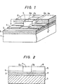
- Figs. 1 and 2 are views for explaining one embodiment of a thermal head according to the present invention.
- a substrate 1 is made of, e.g., ceramics, and a heat accumulating member 2 made of, e.g., glaze is layered thereon.
- a plurality of minute heating resistors 3 made of, e.g., a chromium-silicon (Cr-Si) mixture are juxtaposed on the surface of the heat accumulating member 2 in a manner to be spaced from each other.
- a pair of electrodes 4 made of an electrically conductive material such as aluminum are disposed on each of the heating resistors 3 at a predetermined interval.
- a protective member 5 is disposed as a layer so as to cover the heating resistors 3 and the electrodes 4.
- This protective member 5 consists of two layers; an oxidation-proof layer of silicon oxide (Si0 2 ) or the like for preventing the oxidation of the aforecited heating resistors 3 and electrodes 4, and a wear-proof layer of tantalum oxide (Ta 2 0 5 ) or the like for preventing the wear of the oxidation-proof layer.
- the protective member 5 can serve as both an oxidation-proof layer and a wearproof layer.
- the protective member 5 is formed of a single layer.
- Thermally conductive members 7 which are electrically insulating are disposed for respective heating dots in only those parts of the protective member 5 which correspond to the heating portions 3a of the heating resistors 3.
- One surface of each member 7 is thermally contacted with a heating portion 3a and the other surface 6a opposing the heating portion is exposed to the surrounding atmosphere and is placed at the same plane as that of a head surface.
- D, and D 2 denote the ends of the printing dot portion 6a.
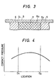
- Figs. 3 and 4 illustrate the state of contact between the head and a thermosensitive sheet 9 such as inked film or heat-sensitive color developing paper and the distribution of contact pressures at that time, respectively.
- a thermosensitive sheet 9 such as inked film or heat-sensitive color developing paper
- the axis of abscissas represents the position of contact between the head surface and the thermosensitive sheet 9, and the axis of ordinates the contact pressure.
- the thermosensitive sheet 9 such as inked film or heat-sensitive color developing paper lies in contact with the whole area of the printing dot portion of the head surface 6, and the contact pressure distribution at that time becomes substantially uniform and favorable also at the ends D" D 2 of the printing dot portion 6a as illustrated in Fig. 4. Therefore, a printed dot is free from nonuniformity in density and has a fixed size, to become a clearly demarcated one of high quality or one of high picture quality and high resolution.
- the thermally conductive member 7 is 10-1000 times greater in the thermal conductivity K than the surrounding protective member 5.
- the distance by which heat propagates during a period of time t is proportional to ⁇ D
- the distance at which the heat gets within the identical period of time is 3-30 times greater in the thermally conductive member 7 than in the protective member 5.
- the temperature difference between the heating portion 3a of the heating resistor 3 and the printing dot portion 6a of the head surface is small, and the leakage of the heat to the surroundings decreases.
- the printing dot portion 6a at the head surface 6 is not indented but is even as described before, the head comes into favorable touch with the thermosensitive sheet 9 such as inked film or heat-sensitive color developing paper.
- thermosensitive sheet 9 such as inked film or heat-sensitive color developing paper.
- the temperature of the head surface 6 rises only in the part of the printing dot portion 6a formed of the thermally conductive member 7 and hardly rises in the surroundings. Accordingly the thermal independence of the respective printed dots at the head surface 6 is high, and the thermal conductivity is high, so that the temperatures of the printing dot portions 6a become substantially uniform. Thus, printing clearly demarcated and uniform in density is possible, and a high printing quality can be attained.
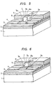
- Figs. 5-13 show other embodiments of the thermal head of the present invention, in which the same symbols as in Figs. 1 and 2 indicate identical portions.
- the thermally conductive member 7 is so shaped that the surface area of a side 7a lying in contact with the heating portion 3a is larger than the surface area of a side 7b at the surface of the printing dot portion 6a.
- the examples shown in Figs. 5 and 6 are such that the shape of the thermally conductive member 7 is steppedly changed, and the examples shown in Figs. 7 and 8 are such that the shape of the thermally conductive member 7 is continuously changed.
- Such construction has the effects of the embodiment shown in Fig. 1.
- the geometries of the printing dot portion 6a can be determined without any regard to the geometries of the heating portion 3a. Accordingly, printing of high resolution is permitted by making the geometries of the printing dot portion 6a small. Conversely, since the geometries of the heating portion 3a can be determined irrespective of those of the printing dot portion 6a, there is also the advantage that allowance is made for the setting of the resistance of the heating portion 3a or the applied power thereto.
- the embodiment shown in Fig. 9 is such that the sectional width of the side 7a of the thermally conductive member 7 lying in contact with the heating portion 3a is made greater than the sectional width of the side 7b at the surface of the printing dot portion 6a in the direction of the electrodes and smaller in the direction of the adjacent dots.
- the present embodiment brings forth effects similar to those of the respective embodiments mentioned before, and it can also enhance the printing quality or picture quality because the clearance between the adjacent printed dots becomes smaller.
- the thermally conductive member 7 is placed directly on the upper surface of the heating portion 3a thereby to be thermally joined with the heating portion 3a. Therefore, the thermally conductive member 7 must be of an electrically insulating material.
- the embodiment shown in Fig. 10 is such that the thermally conductive member 7 is disposed on the upper surface of the heating portion 3a through an electrically insulating member 8 which is formed to be thinner than the protective member 5. Then, the thermally conductive member 7 may well be made of an electrically conductive material such as metal.
- the embodiment 11 is such that all the heating resistors 3 and the electrodes 4 are coated with the electrically insulating member so as to be covered, whereupon the protective member 5 is disposed and has the thermally conductive members 7 stacked on only its parts corresponding to the heating dot portions 3a.
- the electrically insulating member 8 functions as a sealing member, the external air does not enter through the interspace between the thermally conductive member 7 and the protective member 5.
- the embodiment lowers much the possibility of oxidation of the heating resistors 3 as well as the electrodes 4 and makes it possible to expect the effect of the enhancement of the lifetime of the head.
- the electrically insulating member 8 is formed thinner than the protective member 5, a high thermal resistance does not arise, and effects similar to those of the embodiment shown in Figs. 1 and 2 can be brought forth.
- the geometries of the printing dot portion 6a can be selected at will by changing the shape of the thermally conductive member 7 stepwise or continuously as shown in Figs. 5-9.
- the coating with the electrically insulating member 8 shown in Fig. 11 may be disposed so as to cover all the electrodes 4 and the thermally conductive member 7 as illustrated in Fig. 12 with such construction, effects similar to those of the example shown in Fig. 11 can be attained.
- the thickness of the protective member 5 needs to be increased by the thickness of the electrically insulating member 8 so as to render the head surface even with the uppermost surface of the member 8.
- the electrically insulating member 8 may well be disposed so as to cover the entire head surface 6 as illustrated in Fig. 13. With such construction, effects similar to those of the structure shown in Fig. 11 or Fig. 12 can be attained.
- the electrically insulating member 8 may well be replaced with an electrically conductive member.
- the touch between the head and the thermosensitive sheet is favorable owing to uniform contact pressures, and the temperature distribution of the printing head portions can be made favorable, so that printing of high quality and high resolution is permitted.
Claims (12)
Applications Claiming Priority (2)
| Application Number | Priority Date | Filing Date | Title |
|---|---|---|---|
| JP243981/83 | 1983-12-26 | ||
| JP58243981A JPS60137670A (ja) | 1983-12-26 | 1983-12-26 | 感熱ヘツド |
Publications (3)
| Publication Number | Publication Date |
|---|---|
| EP0146870A2 EP0146870A2 (de) | 1985-07-03 |
| EP0146870A3 EP0146870A3 (en) | 1987-08-05 |
| EP0146870B1 true EP0146870B1 (de) | 1990-07-04 |
Family
ID=17111925
Family Applications (1)
| Application Number | Title | Priority Date | Filing Date |
|---|---|---|---|
| EP84115180A Expired EP0146870B1 (de) | 1983-12-26 | 1984-12-11 | Thermokopf |
Country Status (4)
| Country | Link |
|---|---|
| US (1) | US4587399A (de) |
| EP (1) | EP0146870B1 (de) |
| JP (1) | JPS60137670A (de) |
| DE (1) | DE3482650D1 (de) |
Families Citing this family (7)
| Publication number | Priority date | Publication date | Assignee | Title |
|---|---|---|---|---|
| JPH01272466A (ja) * | 1988-04-26 | 1989-10-31 | Copal Co Ltd | サーマルヘッド |
| GB2229400B (en) * | 1989-03-20 | 1993-06-23 | Shinko Electric Co Ltd | Thermal head |
| US5099257A (en) * | 1989-05-10 | 1992-03-24 | Matsushita Electric Industrial Co., Ltd. | Thermal head with an improved protective layer and a thermal transfer recording system using the same |
| JP2010052362A (ja) * | 2008-08-29 | 2010-03-11 | Canon Inc | サーマルヘッドおよびサーマルプリンタ |
| JP5210090B2 (ja) * | 2008-08-29 | 2013-06-12 | キヤノン株式会社 | サーマルヘッドおよびサーマルプリンタ |
| JP5670076B2 (ja) * | 2010-03-26 | 2015-02-18 | 東芝ホクト電子株式会社 | サーマルプリントヘッドおよびその製造方法 |
| JP7392321B2 (ja) * | 2019-08-19 | 2023-12-06 | セイコーエプソン株式会社 | 電気光学装置および電子機器 |
Family Cites Families (8)
| Publication number | Priority date | Publication date | Assignee | Title |
|---|---|---|---|---|
| US4259564A (en) * | 1977-05-31 | 1981-03-31 | Nippon Electric Co., Ltd. | Integrated thermal printing head and method of manufacturing the same |
| US4203025A (en) * | 1977-08-19 | 1980-05-13 | Hitachi, Ltd. | Thick-film thermal printing head |
| JPS5634467A (en) * | 1979-08-30 | 1981-04-06 | Mitsubishi Electric Corp | Thermal head |
| JPS5813703A (ja) * | 1981-07-20 | 1983-01-26 | ユニ・チヤ−ム株式会社 | 使い捨ておむつの伸縮部材の取付け方法 |
| JPS5887077A (ja) * | 1981-11-19 | 1983-05-24 | Nec Corp | サ−マルヘツド |
| JPS58199175A (ja) * | 1982-05-17 | 1983-11-19 | Nec Corp | サ−マルヘツド |
| JPS58203070A (ja) * | 1982-05-21 | 1983-11-26 | Fujitsu Ltd | サ−マルヘツド |
| JPS5983683A (ja) * | 1982-11-04 | 1984-05-15 | Nec Corp | セラミツクサ−マルヘツド |
-
1983
- 1983-12-26 JP JP58243981A patent/JPS60137670A/ja active Granted
-
1984
- 1984-12-11 DE DE8484115180T patent/DE3482650D1/de not_active Expired - Lifetime
- 1984-12-11 EP EP84115180A patent/EP0146870B1/de not_active Expired
- 1984-12-19 US US06/683,499 patent/US4587399A/en not_active Expired - Fee Related
Also Published As
| Publication number | Publication date |
|---|---|
| JPS60137670A (ja) | 1985-07-22 |
| US4587399A (en) | 1986-05-06 |
| DE3482650D1 (en) | 1990-08-09 |
| JPH0582302B2 (de) | 1993-11-18 |
| EP0146870A2 (de) | 1985-07-03 |
| EP0146870A3 (en) | 1987-08-05 |
Similar Documents
| Publication | Publication Date | Title |
|---|---|---|
| EP0194528B1 (de) | Drucker mit Thermokopf | |
| EP0146870B1 (de) | Thermokopf | |
| US4837586A (en) | Image contrast by thermal printers | |
| JP2583965B2 (ja) | サーマルヘッド | |
| US5021806A (en) | Thermal head | |
| JPS6213367A (ja) | サ−マルヘツド | |
| US5426451A (en) | Print head with pixel size control for resistive ribbon thermal transfer printing | |
| EP0182133B1 (de) | Wärmekopf für Wärmedrucker | |
| JPH06135031A (ja) | サーマルヘッド | |
| JPH0711981Y2 (ja) | サーマルプリントヘッド | |
| JPH1029335A (ja) | サーマルヘッド | |
| JPH11157111A (ja) | サーマルヘッド | |
| JPS58114977A (ja) | サ−マルヘツド装置 | |
| JP3099431B2 (ja) | サ−マルヘッド | |
| JPS59133079A (ja) | 感熱ヘツド | |
| JPH0234361A (ja) | サーマルプリントヘッド | |
| JP2526911Y2 (ja) | サ−マルヘッド | |
| JPH04110165A (ja) | サーマルヘッドおよびその製造方法 | |
| JP3038944B2 (ja) | 厚膜型サーマルヘッド | |
| JPH02117856A (ja) | サーマルヘッド | |
| JPH01234265A (ja) | 感熱記録ヘツド | |
| JPS60225771A (ja) | 感熱記録ヘツド | |
| JPH0647295B2 (ja) | サ−マルヘツドの製造方法 | |
| JPS6183056A (ja) | サ−マルヘツド | |
| JPH04296570A (ja) | サーマルヘッド |
Legal Events
| Date | Code | Title | Description |
|---|---|---|---|
| PUAI | Public reference made under article 153(3) epc to a published international application that has entered the european phase |
Free format text: ORIGINAL CODE: 0009012 |
|
| 17P | Request for examination filed |
Effective date: 19841211 |
|
| AK | Designated contracting states |
Designated state(s): DE FR GB IT NL |
|
| PUAL | Search report despatched |
Free format text: ORIGINAL CODE: 0009013 |
|
| AK | Designated contracting states |
Kind code of ref document: A3 Designated state(s): DE FR GB IT NL |
|
| 17Q | First examination report despatched |
Effective date: 19881230 |
|
| GRAA | (expected) grant |
Free format text: ORIGINAL CODE: 0009210 |
|
| AK | Designated contracting states |
Kind code of ref document: B1 Designated state(s): DE FR GB IT NL |
|
| REF | Corresponds to: |
Ref document number: 3482650 Country of ref document: DE Date of ref document: 19900809 |
|
| ET | Fr: translation filed | ||
| ITF | It: translation for a ep patent filed |
Owner name: MODIANO & ASSOCIATI S.R.L. |
|
| ITTA | It: last paid annual fee | ||
| PLBE | No opposition filed within time limit |
Free format text: ORIGINAL CODE: 0009261 |
|
| STAA | Information on the status of an ep patent application or granted ep patent |
Free format text: STATUS: NO OPPOSITION FILED WITHIN TIME LIMIT |
|
| 26N | No opposition filed | ||
| PGFP | Annual fee paid to national office [announced via postgrant information from national office to epo] |
Ref country code: GB Payment date: 19991201 Year of fee payment: 16 |
|
| PGFP | Annual fee paid to national office [announced via postgrant information from national office to epo] |
Ref country code: FR Payment date: 19991215 Year of fee payment: 16 |
|
| PGFP | Annual fee paid to national office [announced via postgrant information from national office to epo] |
Ref country code: DE Payment date: 19991230 Year of fee payment: 16 |
|
| PGFP | Annual fee paid to national office [announced via postgrant information from national office to epo] |
Ref country code: NL Payment date: 19991231 Year of fee payment: 16 |
|
| PG25 | Lapsed in a contracting state [announced via postgrant information from national office to epo] |
Ref country code: GB Free format text: LAPSE BECAUSE OF NON-PAYMENT OF DUE FEES Effective date: 20001211 |
|
| PG25 | Lapsed in a contracting state [announced via postgrant information from national office to epo] |
Ref country code: NL Free format text: LAPSE BECAUSE OF NON-PAYMENT OF DUE FEES Effective date: 20010701 |
|
| GBPC | Gb: european patent ceased through non-payment of renewal fee |
Effective date: 20001211 |
|
| PG25 | Lapsed in a contracting state [announced via postgrant information from national office to epo] |
Ref country code: FR Free format text: LAPSE BECAUSE OF NON-PAYMENT OF DUE FEES Effective date: 20010831 |
|
| NLV4 | Nl: lapsed or anulled due to non-payment of the annual fee |
Effective date: 20010701 |
|
| REG | Reference to a national code |
Ref country code: FR Ref legal event code: ST |
|
| PG25 | Lapsed in a contracting state [announced via postgrant information from national office to epo] |
Ref country code: DE Free format text: LAPSE BECAUSE OF NON-PAYMENT OF DUE FEES Effective date: 20011002 |