EP0146531B1 - DÜnnschichttrockner für fliessfähige Stoffe - Google Patents
DÜnnschichttrockner für fliessfähige Stoffe Download PDFInfo
- Publication number
- EP0146531B1 EP0146531B1 EP84890245A EP84890245A EP0146531B1 EP 0146531 B1 EP0146531 B1 EP 0146531B1 EP 84890245 A EP84890245 A EP 84890245A EP 84890245 A EP84890245 A EP 84890245A EP 0146531 B1 EP0146531 B1 EP 0146531B1
- Authority
- EP
- European Patent Office
- Prior art keywords
- drier
- area
- distributor ring
- rotor shaft
- wall
- Prior art date
- Legal status (The legal status is an assumption and is not a legal conclusion. Google has not performed a legal analysis and makes no representation as to the accuracy of the status listed.)
- Expired
Links
- 239000010409 thin film Substances 0.000 title description 12
- 239000000428 dust Substances 0.000 claims abstract description 47
- 238000001035 drying Methods 0.000 claims abstract description 29
- 239000002245 particle Substances 0.000 claims abstract description 28
- 239000007789 gas Substances 0.000 claims abstract description 18
- 239000007787 solid Substances 0.000 claims abstract description 18
- 239000000126 substance Substances 0.000 claims abstract description 10
- 230000009969 flowable effect Effects 0.000 claims abstract description 6
- 230000000149 penetrating effect Effects 0.000 claims abstract 2
- 239000004033 plastic Substances 0.000 claims description 23
- 229920003023 plastic Polymers 0.000 claims description 23
- 239000000463 material Substances 0.000 claims description 16
- 238000009833 condensation Methods 0.000 claims description 8
- 230000005494 condensation Effects 0.000 claims description 8
- 229920000034 Plastomer Polymers 0.000 claims description 7
- 239000000919 ceramic Substances 0.000 claims description 5
- 239000011810 insulating material Substances 0.000 claims description 4
- 229920001296 polysiloxane Polymers 0.000 claims description 4
- 229920002430 Fibre-reinforced plastic Polymers 0.000 claims description 2
- 239000010425 asbestos Substances 0.000 claims description 2
- 239000000835 fiber Substances 0.000 claims description 2
- 239000011151 fibre-reinforced plastic Substances 0.000 claims description 2
- 229910052895 riebeckite Inorganic materials 0.000 claims description 2
- 230000001174 ascending effect Effects 0.000 claims 2
- 239000011888 foil Substances 0.000 claims 1
- 239000011490 mineral wool Substances 0.000 claims 1
- 239000002609 medium Substances 0.000 description 13
- 238000010438 heat treatment Methods 0.000 description 8
- 239000011248 coating agent Substances 0.000 description 6
- 238000000576 coating method Methods 0.000 description 6
- 238000001704 evaporation Methods 0.000 description 6
- 238000009413 insulation Methods 0.000 description 6
- 238000000926 separation method Methods 0.000 description 6
- 229910000831 Steel Inorganic materials 0.000 description 5
- 230000008020 evaporation Effects 0.000 description 5
- 239000010959 steel Substances 0.000 description 5
- 230000015572 biosynthetic process Effects 0.000 description 4
- 229920002313 fluoropolymer Polymers 0.000 description 3
- 239000007788 liquid Substances 0.000 description 3
- 239000002184 metal Substances 0.000 description 3
- 230000002093 peripheral effect Effects 0.000 description 3
- 230000008021 deposition Effects 0.000 description 2
- 229920001971 elastomer Polymers 0.000 description 2
- 239000004744 fabric Substances 0.000 description 2
- 239000010419 fine particle Substances 0.000 description 2
- 238000005457 optimization Methods 0.000 description 2
- 239000006223 plastic coating Substances 0.000 description 2
- 230000000630 rising effect Effects 0.000 description 2
- 239000011343 solid material Substances 0.000 description 2
- 229910001220 stainless steel Inorganic materials 0.000 description 2
- 239000010935 stainless steel Substances 0.000 description 2
- 206010044565 Tremor Diseases 0.000 description 1
- 230000001133 acceleration Effects 0.000 description 1
- 230000002730 additional effect Effects 0.000 description 1
- 230000003750 conditioning effect Effects 0.000 description 1
- 238000001816 cooling Methods 0.000 description 1
- 238000005260 corrosion Methods 0.000 description 1
- 230000007797 corrosion Effects 0.000 description 1
- 230000000694 effects Effects 0.000 description 1
- 239000000806 elastomer Substances 0.000 description 1
- 239000013536 elastomeric material Substances 0.000 description 1
- 239000012526 feed medium Substances 0.000 description 1
- 239000010408 film Substances 0.000 description 1
- 239000006260 foam Substances 0.000 description 1
- 239000003365 glass fiber Substances 0.000 description 1
- 239000011491 glass wool Substances 0.000 description 1
- 239000012774 insulation material Substances 0.000 description 1
- 230000014759 maintenance of location Effects 0.000 description 1
- 238000000034 method Methods 0.000 description 1
- 238000005192 partition Methods 0.000 description 1
- 238000003825 pressing Methods 0.000 description 1
- 238000007790 scraping Methods 0.000 description 1
- 238000007493 shaping process Methods 0.000 description 1
- 229920003002 synthetic resin Polymers 0.000 description 1
- 239000000057 synthetic resin Substances 0.000 description 1
- 239000010891 toxic waste Substances 0.000 description 1
Images

Classifications
-
- B—PERFORMING OPERATIONS; TRANSPORTING
- B01—PHYSICAL OR CHEMICAL PROCESSES OR APPARATUS IN GENERAL
- B01D—SEPARATION
- B01D1/00—Evaporating
- B01D1/22—Evaporating by bringing a thin layer of the liquid into contact with a heated surface
- B01D1/222—In rotating vessels; vessels with movable parts
- B01D1/223—In rotating vessels; vessels with movable parts containing a rotor
- B01D1/225—In rotating vessels; vessels with movable parts containing a rotor with blades or scrapers
- B01D1/226—In rotating vessels; vessels with movable parts containing a rotor with blades or scrapers in the form of a screw or with helical blade members
-
- F—MECHANICAL ENGINEERING; LIGHTING; HEATING; WEAPONS; BLASTING
- F26—DRYING
- F26B—DRYING SOLID MATERIALS OR OBJECTS BY REMOVING LIQUID THEREFROM
- F26B17/00—Machines or apparatus for drying materials in loose, plastic, or fluidised form, e.g. granules, staple fibres, with progressive movement
- F26B17/18—Machines or apparatus for drying materials in loose, plastic, or fluidised form, e.g. granules, staple fibres, with progressive movement with movement performed by rotating helical blades or other rotary conveyors which may be heated moving materials in stationary chambers, e.g. troughs
- F26B17/22—Machines or apparatus for drying materials in loose, plastic, or fluidised form, e.g. granules, staple fibres, with progressive movement with movement performed by rotating helical blades or other rotary conveyors which may be heated moving materials in stationary chambers, e.g. troughs the axis of rotation being vertical or steeply inclined
-
- F—MECHANICAL ENGINEERING; LIGHTING; HEATING; WEAPONS; BLASTING
- F26—DRYING
- F26B—DRYING SOLID MATERIALS OR OBJECTS BY REMOVING LIQUID THEREFROM
- F26B25/00—Details of general application not covered by group F26B21/00 or F26B23/00
- F26B25/005—Treatment of dryer exhaust gases
- F26B25/007—Dust filtering; Exhaust dust filters
-
- F—MECHANICAL ENGINEERING; LIGHTING; HEATING; WEAPONS; BLASTING
- F26—DRYING
- F26B—DRYING SOLID MATERIALS OR OBJECTS BY REMOVING LIQUID THEREFROM
- F26B3/00—Drying solid materials or objects by processes involving the application of heat
- F26B3/18—Drying solid materials or objects by processes involving the application of heat by conduction, i.e. the heat is conveyed from the heat source, e.g. gas flame, to the materials or objects to be dried by direct contact
- F26B3/20—Drying solid materials or objects by processes involving the application of heat by conduction, i.e. the heat is conveyed from the heat source, e.g. gas flame, to the materials or objects to be dried by direct contact the heat source being a heated surface, e.g. a moving belt or conveyor
Definitions
- the invention relates to a dryer, in particular a vertical thin-film dryer, for drying flowable materials, which has a feed area, a heated drying area and a vapor-steam area and a rotor passing through these areas, the rotor shaft in the feed area having a rotating one close to it Dryer wall reaching distribution ring, with which the flowable substances fed in the feed area are distributed on the inside wall of the dryer and through its interior formed as a passage opening, the vapors and / or gases generated during the drying of the substances from the drying area located below the distribution ring in the above the distribution ring the vapor vapor area located.
- a rotary film column which works on the principle of partial evaporation and condensation and consists of a heatable column jacket in which there is a coolable vane rotor. On the wing rotor, between the wiper blades, there are horizontally extending constriction plates with respect to the rising steam flow.
- a rotating separation device is known from FR-A-1 047 794, in which the rising gases are passed through horizontal floors.
- US-A-3 654 981, 2208466 and GB-A-2 077 414 show conventional vaporizers also without means to improve the vapor-vapor separation efficiency.
- FR-A-2379305 shows scrapers for the wall of a thin film evaporator.
- DE-A-28 30 874 discloses a thin-film treatment apparatus, in particular thin-film evaporator, with a rotor with a shaft and a rotationally symmetrical one arranged around it.
- metric wall the rotor in the feed area of the material to be evaporated extending to the wall having essentially radial, elastically resilient stripping elements.
- the scraper elements are designed in sheet form in a manner known per se, these and the rotor being at least partially coated with an elastomeric material in order to prevent particles from being deposited thereon. It is also provided that the stripping elements are movably connected to the rotor.
- horizontal plates rotating with the rotor of an evaporator are known.
- thin layers of the medium to be dried are preferably applied continuously to heated surfaces, where the evaporable component, mostly with the additional action of vacuum, is converted into the gas phase. If necessary with thin-film evaporators, but always with thin-film dryers, a more or less stable layer of solid residues remains on the heating surface. This layer is continuously removed from the heating surface, resulting in the basic structure of a thin-layer dryer as follows.
- a heating surface arranged rotationally symmetrically around a rotor together with the stripping elements dries the medium introduced through a feed line in thin layers with the aid of the centrifugal forces generated by the rotor or a distributor ring.
- the dry residue is continuously removed from the heating surface by means of the scraper elements mounted on the rotor shaft inside the distributor ring.
- the solid material continuously removed from the heating surface trickles downward, so that the solid material collects and can be discharged.
- the structure of the rotor is particularly important for the trouble-free functioning of a dryer.
- a suitable rotor design ensures that the mostly fine-particle solids that arise during drying can be properly separated from the evaporating liquid medium in the drying area and discharged as quantitatively as possible from the drying area. In other words, it must be ensured that as far as possible no solid in the form of dust particles is entrained by the outgoing steam or gas and is only deposited in the peripheral systems of the dryer.
- the aim of the present invention is to design a dryer of the type mentioned at the outset in such a way that the demands placed on it can be met, namely to avoid that significant portions of the dry product in the form of dust particles are entrained by the outflowing steam or gas are discharged from the dryer.
- this is achieved in that in the vapor-vapor region of the dryer for holding back solid particles carried with vapor vapors in the dryer on the rotor shaft close to the dryer wall, dust-collecting elements are attached, which have inclined or perpendicular surfaces with respect to the rotor axis and with the rotor shaft are elastically connected or movably mounted on it and can be set into a shaking, oscillating and / or vibrating movement during operation by the rotation of the rotor shaft.
- the invention thus relates to a dryer, in particular a vertical thin-film dryer, whose task compared to the usual dryers is to retain the dust-like fines that occur during the drying process, which are normally discharged with the vapors being drawn off, as quantitatively as possible in the dryer housing, with the actual dry product, together with this from the dryer according to the system execute and thus increase the yield.
- the vertically mounted cylindrical dryer jacket is divided into a lower heated dryer area and an unheated steam vapor area above it, with the feed area between these zones, where the material to be dried is fed into the system.
- the rotor of the dryer is mounted in a rotationally symmetrical manner over the entire length inside the cylindrical dryer jacket.
- the rotor elements required for the function are attached to the rotor axis in accordance with the three zones (from bottom to top: dryer area, infeed area, steam / vapor area).
- these are stripping elements that are necessary to spread thin layers of the medium applied by the centrifugal forces of the rotor via the distributor ring onto the hot dryer jacket and to remove them continuously after drying.
- the removed dry product trickles downwards when the dryer is built up vertically, from where it is collected and discharged.
- the steam flowing in from the dryer area via the distributor ring is made to have increased turbulence by dust separating elements according to the invention, which have moveable fastened to the rotor shaft and have inclined surfaces, the dust particles being coarsened and deposited on the dust separating elements or trickling downwards.
- the vibrations caused by the stripping elements attached to the rotor in the dryer area are transmitted via the rotor as shaking movements to the movable dust separating elements, so that the dust deposits deposited here are shaken off and trickled downwards.
- the solid components thus obtained from the dusts return through the dry inner area of the distributor ring equipped according to the invention, or outside via the feed zone, back into the dryer area and are combined with the dry product produced.
- Appropriate temperature setting in the workflow prevents the formation of droplets as the steam rises and thus the formation of moist lumps with the dusts carried along in the steam / vapor area, so that the measures according to the invention achieve the increased dry product yield.
- the dryer according to the invention thus differs from its intended use or its task and also from the structure of the known devices, none of which can be used for the separation of solid particles; Coarsening of the dust particles and shaking the particles back into the dry area cannot be carried out with them.
- the vapors vapor space no separating elements for dust particles are provided in the known devices, so that the basic structure of these devices is completely different.
- the outflowing steam is given increased turbulence or the dust is subjected to centrifugal acceleration, so that the dry product particles can be intercepted, coarsened and returned to the actual drying area.
- the interior and / or the inner walls of the distributor ring with respect to its outer wall are heat-insulated and / or heatable and / or the inner walls of the distributor ring consist of heat-insulating material.
- This inventive design of the distributor ring in the feed zone of the dryer prevents the cold medium introduced from condensing the outflowing steam and / or gas; thus the interior or the outflow openings for the steam or the gas can be inside the Distribution ring from damp deposits are kept free and the steam or gas flow from this area unhindered into the vapor steam area.
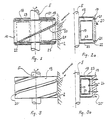
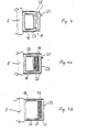
- FIGS. 2, 2a, 3, 3a, 4, 4a and 4b show different embodiments of a distributor ring, partly in section
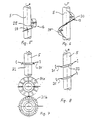
- FIGS. 5-12 show different embodiments of dust separating elements.
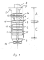
- a thin-film dryer 1 shows a thin-film dryer 1, which is advantageously constructed vertically. is and usually has a cylindrical peripheral shape.
- a heatable cylindrical dryer jacket 2 has a medium feed opening 3 and is extended above it.
- This extension 4 can also be cylindrical, but can also have a steep conical shape that widens upwards, which enables the rotor or the rotor shaft 5 to be easily removed upwards.
- This extension 4, which can correspond to approximately 20-50% of the total length of the dryer 1, does not have to be heated, it is sufficient effective insulation against the environment, which condenses the medium vapors or gases inside or on the. Inner wall of extension 4 prevented. At the upper end of this extension there is a steam outlet 6.
- the end is formed by a corresponding flat or curved flange with a bushing for the rotor shaft 5, which is set in rotation by a drive 8 from above.
- the rotor which extends over the entire length of the dryer 1, has a functional function in the three functional areas of the dryer, the drying area C, the feed-in area B and the vapor vapor area A and consists of the rotor shaft 5, the stripping elements 11 in the drying area C, a distributor ring 10, which is at least partially located in the feed area B, and dust separating elements 13 in the steam area A.
- the lower, heated, actual drying area C, in which the stripping elements 11 are arranged, is not discussed in detail in connection with the present invention, since a corresponding training of the rotor in this area is known from US-A-4 208 243.
- the vapors and / or gases produced in the heated drying area C are discharged upwards from this and pass through the distribution ring 10, which is constantly cooled by the cold feed medium, which ensures that the medium or the substances to be dried are applied as evenly as possible in thin layers on the Heating jacket 2 of the dryer 1 can be applied.
- the steam or gases generally flow through the inner open area of the distributor ring 10 (arrow 12) and it has hitherto been difficult to avoid that portions of the steam condense and, with the fine portions of the dry product carried along, lead to a narrowing of the through-openings in the distributor ring 10, which disrupts the operation However, this is avoided by the formation of the distributor ring 10.
- the rotor shaft 5 is equipped with dust separating elements 13 (shown schematically in FIG. 1) which generate increased turbulence in the steam flow and which, by suitable shaping and choice of material, ensure that the dust particles largely agglomerate in the steam space 14 and deposit on the wall of the dryer 1 and can be returned to the lower area.
- the formation of the distributor ring 10 in the feed area B and the dust separating elements 13 in the steam area A have the purpose of concentrating the dried solid as quantitatively as possible in the dry area C and in the desired manner, usually in accordance with the gravitation, into a drying room 9 for dry solid bring from which the solid is discharged through a lock 16. This prevents the steam discharged upwards from the dryer 1 from carrying substantial amounts of solids and thus excessively loading the subsequent steam lines, vapor washer, condenser, etc. A requirement that must be taken into account especially when drying and conditioning bio-harmful or toxic waste.
- FIGS. 2 and 3 show exemplary embodiments of the distributor ring 10, which allow the steam or gas to exit the heated drying area C into the steam area A of the dryer 1 as freely as possible.
- a distributor ring 10 consists of a supporting sleeve part 17 fastened to the rotor shaft 5, from which support or webs 18 extend, which carry a ring part 19, which in turn carries a distributor element 20.
- the ring part 19 can be made of corrosion-resistant, thermostable, poorly heat-conducting plastics, e.g. As fluoroplastics, silicone plastics, which are advantageously reinforced with fibers and / or fabrics to increase the mechanical stability (z. B. glass fibers), be made entirely or partially or coated, clad or coated with it.
- fluoroplastics e.g. As fluoroplastics, silicone plastics, which are advantageously reinforced with fibers and / or fabrics to increase the mechanical stability (z. B. glass fibers), be made entirely or partially or coated, clad or coated with it.
- the ring portion 19 of z. B. 3 to 6 spoke-shaped on the rotor shaft 5 fixed (z. B. welded, screwed) or outgoing from the sleeve part 17 webs 18 is carried.
- the attachment of the ring member 19 is carried out, for. B. by sliding the ring member 19 onto the vertical webs 18, which engage in groove-shaped recesses in the ring member 19. Up and down, the ring part 19 is on the end face covered a steel ring 21, which also engages with slots in the webs 18 and is fixed against slipping out of the webs 18 with screwed or cotter pins 22.
- the surfaces of the metal parts inside the distributor ring 10, ie the rotor shaft 5, the webs 18, the sleeve 17, the steel rings 21 and the inner surfaces of the ring part 19, if this is made of metal, are provided with a plastic layer 23, for. B. fluoroplastic, or coated with a ceramic layer.
- a plastic layer 23 for. B. fluoroplastic, or coated with a ceramic layer.
- On the outer periphery of the ring member 19 are expediently attached to the dryer jacket 2 reaching, helically arranged stripping elements 20, which force the conveyed medium from the feed area 13 down into the heated drying area C and placed on the ring part 19, z. B. screwed, riveted or integrated in pre-milled grooves and fixed.
- FIG. 3 and 3a show a further possible embodiment of a distributor ring 10.
- the ring part 19 consists of a plastic body which has screw-shaped recesses 20 'on the outer cylinder surface which distribute the medium in a functionally appropriate manner.
- Crosspieces 18 are made, for example, by screws 24 or rivets, where the crosspieces 18 can be provided with tabs or have a frame shape and are connected to the ring body 19.
- all metal surfaces of the rotor shaft 5 and the supporting webs 18 are provided with a suitable coating in order to avoid steam condensation and solid deposition.
- the interior of the distributor ring 10 is thermally insulated by the plastic body forming the annular body 19 and by the coating of the webs 18 against cooling by the medium fed in, thus preventing condensation of the vapor vapors on cold surfaces.
- FIG. 4 shows a distributor ring 10 with an annular body 19 which is supported by metallic webs 18 covered with a plastic layer 23 and which has chambers or cavities 25 running around in its interior for thermal insulation.
- FIG. 4a shows a distributor ring 10, the metallic ring body 19 or the outside of which is coated with a layer 23 of plastic or ceramic.
- an annular body with one or more chambers 26 is arranged, the thermal insulation materials, for. B. glass wool, synthetic resin foam, asbestos, and. s. w. contain.
- the webs 18, the sleeve 17 and optionally the rotor shaft 5 are in turn provided with a coating 23 made of plastic or ceramic.
- FIG. 4b shows a distributor ring 10 with a metallic ring body 19 carried by metallic webs 18, the webs 18 and the outside of the annular body 19 being provided with a coating 23.
- a partition or shield 27 made of plastic or ceramic is also carried by the webs 18, a heat insulation layer 26 being arranged between the ring body 19 and the shield 27.
- a rubber-elastic plastic coating 23 has in addition to the thermal insulation the advantage that sticking of condensed particles is prevented by the elasticity of the plastic coating and the particles by their own movement, for. B. vibration, the coating fall off.
- the thickness of the coating or thermal insulation is dimensioned such that the temperature of the interior of the distributor ring is raised such that it is above the condensation temperature of the vapors or gases at the pressure prevailing in the dryer.
- FIG. 5-12 show examples of the equipment of the rotor in the vapor-vapor region A, as are provided according to the invention for separating dust particles in the outflowing vapors and / or gases.
- Fig. 5 shows an example of dust separating elements 13, which of mechanically sufficiently stable helically arranged segments 29, z. B. are formed from plastic-coated steel sheet or fiber-reinforced plastomers, which are attached to the rotor shaft 5 with adjustable elastic or resilient brackets 28 and extend close to the dryer wall 2.
- the edge zones of the segments 29 are set in a trembling motion by the movement of the rotor shaft 5, as a result of which dust particles that strike are separated from the turbulent steam flow and can be returned to the actual drying area C via the distributor ring 10.
- the brackets 28 can be coated like the segments 29.
- the areas of the segments 29 increase in the direction of the direction of rotation of the rotor shaft 5, wherein the increase can be changed by rotating the segments 29.
- FIG. 6 A similar embodiment is shown in FIG. 6.
- a strip 30 fastened helically to the rotor shaft 5 and reaching a distance from the dry wall 2 by a gap is not divided into relatively short segments as in FIG. B. in about 2-6 turns over the entire length of the rotor shaft 5 in the steam region A, it to reduce its stiffness, possibly z. B. can be slit or interrupted at 1 to 3 points.
- the attachment or the brackets 28 or the inserts for the brackets 28 on the rotor shaft 5 are, if possible, not rigid.
- Slotted brackets 28, into which the spiral strip or strips 30 are inserted and fixed can, as described above, be connected to the inserts screwed into or welded to the rotor shaft 5 via a joint or a short spiral spring or a rubber bolt, thereby shaking off trapped dust is promoted during operation and its combination with the bulk of the dry product is made possible.
- two to three and also more spiral strips 30 can be mounted in parallel or offset or parallel to one another. will.
- FIG. 7 Another possible embodiment of the dust separating elements 13 is shown in FIG. 7.
- Openwork disks 31 made of plastic-coated steel sheet or of sufficiently mechanically stable plastomers are slotted (31 a) or perforated (31 b) and fastened to the rotor shaft 5 with screwed or welded advantageously resilient tabs 32 in such a way that they are slightly curved or horizontally close to the Reach dryer wall 2.
- a type of baffle can be provided through the offset openings in overlapping disks 31a, 31b in order to increase the turbulence of the outflowing steam.
- the disks 31 are designed so that the edges directed against the dryer wall are relatively thin, so that during operation the dust particles deposited on a disk 31 are loosened by vibration and directed to the dryer wall 2 by centrifugal force. From there, the dust particles are returned to the actual drying area C, as already described above.
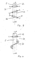
- the upper part of the rotor shaft 5 according to FIG. 8 is in principle equipped with the same disks 31 as the rotor shaft 5 in FIG. 7. Since the disks 31 are fastened in inclined brackets 33 with respect to the axis of the rotor shaft 5, this results during the rotation the tumbling movement a particularly intense turbulence and an additional up-down movement to the vibration mentioned above. Deposited dust particles are thereby shaken off again as coarsened grains and, as already described, conveyed downward over the dryer wall to the main amount of the dry product.
- FIG. 9 shows the combination of horizontal brackets 32 and brackets 33 which are at an angle to one another, equipped with disks 31 which reach close to the dryer wall 2 but do not touch them the rotor shaft 5 and the horizontal, advantageously slightly curved disks 31 are arranged in the upper and lower region thereof, a particularly advantageous combination results.
- the lower disk 31 prevents dust particles from the rotor shaft 5 from reaching the inner evaporation opening of the distributor ring 10, the upper disk 31 particularly advantageously blocks the escape of the finest dust particles into the evaporation or vapor line of the dryer 1.
- the disk perforation or slitting can be carried out by pressing, wherein advantageously perforated or slot edges lagging in the direction of rotation are raised in relation to the plane of the disk.
- 11 and 12 show dust separating elements 13, which are formed by vanes 34, which can be pivoted and are fastened to the rotor shaft 5 with joints in screwed-on or welded-on brackets 28 such that they are directed against the dryer wall 2 by rotation by the centrifugal force and reach close to them.
- Their inclination with respect to a plane perpendicular to the rotor shaft 5 and in the direction of rotation of the rotor shaft 5 can be selected and can range from a vertical position to an oblique position to a horizontal position.
- Through an overlapping arrangement of the wings 34 is in the lower part of the steam. rich A the interior of the distributor ring 10 is shielded so that the steam outlet openings can no longer be narrowed from solid deposits.
- a downward and outward movement of the dust particles can be achieved by a smaller inclination of the wings 34.
- downward and outward movement of the dust particles can be achieved by slightly inclining the wings 34.
- the direct steam outlet can be disturbed again by a horizontal arrangement of the vanes 34 and the escape of the solid particles into the evaporation line 6 can be prevented as far as possible.
- the material for the wings 34 is recommended to use the material for the wings 34 with stainless steel or fabric or fiber-reinforced plastic coated with fluoroplastics, in order to additionally prevent and hold dry products from sticking to the blades which vibrate during the working process, advantageously due to the resilient holders to avoid steam condensation.
- the rotor shaft 5 itself at least partially with plastomers, fluorinated plastics or silicone to coat plastics so that the rotor shaft 5 as well as the dust separating elements 13 and the distributor ring 10 can be kept largely free of deposits.
- the optimization of the vertical thin-film dryer according to the invention is not limited to the examples given.
- a combination of suitable heating with simultaneous thermal insulation of the distributor interior is a particularly advantageous embodiment variant of the dryer distributor ring 10 in question.
Landscapes
- Engineering & Computer Science (AREA)
- Mechanical Engineering (AREA)
- General Engineering & Computer Science (AREA)
- Chemical & Material Sciences (AREA)
- Chemical Kinetics & Catalysis (AREA)
- Life Sciences & Earth Sciences (AREA)
- Microbiology (AREA)
- Drying Of Solid Materials (AREA)
- Processing And Handling Of Plastics And Other Materials For Molding In General (AREA)
Description
- Die Erfindung betrifft einen Trockner, insbesondere vertikaler Dünnschichttrockner, zum Trocknen von fließfähigen Stoffen, der einen Einspeisebereich, einen beheizten Trockenbereich und einen Brüden-Dampfbereich und einen diese Bereiche durchsetzenden Rotor aufweist, wobei die Rotorwelle in dem Einspeisebereich einen mit ihr umlaufenden bis nahe an die Trocknerwand reichenden Verteilerring trägt, mit dem die im Einspeisebereich eingespeisten fließfähigen Stoffe auf der Innenwand des Trockners verteilt werden und durch dessen als Durchtrittsöffnung ausgebildeten Innenraum die beim Trocknen der Stoffe entstehenden Dämpfe und/oder Gase aus dem unterhalb des Verteilerringes gelegenen Trockenbereich in den oberhalb des Verteilerringes gelegenen Brüden-Dampfbereich strömen.
- Aus der DE-A-1944466 ist eine Rotations-Filmkolonne bekannt, die nach dem Prinzip der partiellen Verdampfung und Kondensation arbeitet und aus einem heizbaren Kolonnenmantel, in welchem sich ein kühlbarer Flügelrotor befindet, besteht. An dem Flügelrotor sind zwischen den Wischerflügeln in bezug auf den aufsteigenden Dampfstrom horizontal verlaufende Verengungsplatten angebracht. Aus der FR-A-1 047 794 ist eine rotierende Trenneinrichtung bekannt, bei der die aufsteigenden Gase durch horizontale [,ochböden geführt werden. Die US-A-3 654 981, 2208466 und die GB-A-2 077 414 zeigen herkömmliche Verdampfer ebenfalls ohne Einrichtungen zur Verbesserung der Abscheidewirkung im Brüden-Dampfbereich. Die FR-A-2379305 zeigt Abschabeinrichtungen für die Wand eines Dünnschichtverdampfers.
- Aus der DE-A-28 30 874 ist ein Dünnschichtbehandlungsapparat, insbesondere Dünnschichtverdampfer bekannt, mit einem Rotor mit Welle und einer um diesen angeordneten rotationssym- . metrischen Wandung, wobei der Rotor im Zufuhrbereich des einzudampfenden Materials bis zur Wandung reichende im wesentlichen radiale elastisch federnde Abstreifelemente aufweist. Die Abstreifelemente sind in an sich bekannter Weise blattförmig ausgebildet, wobei diese und der Rotor zumindest teilweise mit einem elastomeren Material beschichtet sind, um eine Ablagerung von Teilchen darauf zu verhindern. Es ist ferner vorgesehen, daß die Abstreifelemente mit dem Rotor beweglich verbunden sind. Aus der GB-A-2021 426 sind schließlich mit dem Rotor eines Verdampfers mitrotierende horizontale Platten bekannt.
- Bei Trocknern bzw. Verdampfern, insbesondere Dünnschichttrocknern, die nach dem Prinzip von Dünnschichtverdampfern arbeiten, werden dünne Schichten des zu trocknenden Mediums auf beheizte Flächen vorzugsweise kontinuierlich aufgebracht, wo die verdampfbare Komponente, zumeist unter zusätzlicher Einwirkung von Vakuum, in die Gasphase überführt wird. Gegebenenfalls bei Dünnschichtverdampfern, aber immer bei Dünnschichttrocknern, verbleibt eine mehr oder weniger stabile Schicht von festen Rückständen auf der Heizfläche. Diese Schicht wird kontinuierlich von der Heizfläche entfernt, womit sich der prinzipielle Aufbau eines Dünnschichttrockners wie folgt ergibt. Eine rotationssymmetrisch um einen Rotor samt Abstreifelementen angeordnete Heizfläche trocknet mit Hilfe der durch den Rotor bzw. einen Verteilerring erzeugten Fliehkräfte in dünnen Schichten das durch eine Einspeiseleitung eingebrachte Medium. Von der Heizfläche wird mittels der auf der Rotorwelle innerhalb des Verteilerringes montierten Abstreifelemente der trockene Rückstand laufend entfernt. Bei senkrechter Aufstellung des Trockners rieselt das von der Heizfläche kontinuierlich abgetragene Festmaterial abwärts, so daß sich das Festmaterial sammelt und ausgetragen werden kann. Für ein klagloses Funktionieren eines Trockners ist vor allem der Aufbau des Rotors maßgeblich. Dieser muß die Verteilung des Mediums in gleichmäßig dünne Schichten auf der beheizten Trocknerwand durchführen, das daraus resultierende Trockenprodukt von der Trocknerwand möglichst kontinuierlich und vollständig entfernen und so adaptiert sein, das krustenförmigen Ablagerungen auf den Rotorkomponenten selber, dem Verteilerring und den Abstreifelementen weitgehend vermieden werden. Weiters ist es vorteilhaft, wenn durch eine geeigenete Rotorausführung dafür gesorgt wird, daß die beim Trocknen entstehenden meist feinteiligen Feststoffe im Trockenbereich einwandfrei vom abdampfenden Flüssigmedium abgetrennt und möglichst quantitativ aus dem Trockenbereich ausgetragen werden können. D. h., es muß dafür gesorgt werden, daß tunlichst kein Feststoff in Form von Staubpartikeln vom abgehenden Dampf bzw. Gas mitgerissen wird und erst in den peripheren Anlagen des Trockners abgelagert wird.
- Ziel der vorliegenden Erfindung ist es, einen Trockner der eingangs genannten Art so auszugestalten, daß die an ihn gestellten Forderungen verwirklicht werden können, nämlich zu vermeiden, daß durch den abströmenden Dampf bzw. das abströmende Gas signifikante Anteile des Trockenproduktes in Form von Staubpartikeln mitgerissen und aus dem Trockner ausgetragen werden. Erfindungsgemäß wird dies dadurch erreicht, daß im Brüden-Dampfbereich des Trockners zum Zurückhalten von mit Brüdendämpfen mitgeführten Feststoffanteilen im Trockner auf der Rotorwelle nahe an die Trocknerwand heranreichende Staubabscheideelemente angebracht sind, die in bezug auf die Rotorachse geneigt oder senkrecht verlaufende Flächen besitzen und mit der Rotorwelle elastisch verbunden oder an dieser beweglich gelagert sind und während des Betriebes durch die Rotation der Rotorwelle in eine schüttelnde, schwingende und/oder vibrierende Bewegung versetzbar sind.
- Die Erfindung betrifft somit einen Trockner, insbesondere einen vertikalen Dünnschichttrockner, dessen Aufgabe gegenüber den üblichen Trocknern darin besteht, die beim Trockenvorgang entstehenden staubförmigen Feinanteile, die normalerweise mit den abziehenden Brüden abgeführt werden, möglichst quantitativ im Trocknergehäuse zurückzuhalten, mit dem eigentlichen Trockenprodukt zu vereinigen, mit diesem gemeinsam aus dem Trockner anlagengemäß auszuführen und damit die Ausbeute zu erhöhen.
- Hiezu wird der vertikal montierte zylindrische Trocknermantel in einen unteren beheizten Trocknerbereich und in einen darüber befindlichen unbeheizten Dampf-Brüdenbereich unterteilt, wobei sich zwischen diesen Zonen der Einspeisebereich befindet, wo das zu trocknende Material in die Anlage eingefördert wird. Über die gesamte Länge im Inneren des zylindrischen Trocknermantels ist der Rotor des Trockners rotationssymmetrisch montiert. Auf der Rotorachse sind entsprechend den drei Zonen (von unten nach oben : Trocknerbereich, Einspeisebereich, Dampf-Brüdenbereich) die für die Funktion erforderlichen Rotorelemente angebracht. Im beheizten Trocknerbereich sind dies Abstreifelemente, die notwendig sind, um das durch die Fliehkräfte des Rotors über den Verteilerring auf den heißen Trocknermantel aufgebrachte Medium zu dünnen Schichten auszuspreiten und nach dem Trocknen laufend zu entfernen. Das dabei abgetragene Trockenprodukt rieselt bei vertikalem Aufbau des Trockners abwärts, von wo es gesammelt und ausgetragen wird.
- Der beim Trocknen entstehende Dampf entweicht nach oben und nimmt dabei staubförmige Feinanteile mit. Damit dieser Dampf beim Durchgang durch den Verteilerring nicht kondensiert und hier die Feinanteille ablagert und den Verteilerring verkrustet - der Verteilerring wird durch das zugeförderte Medium dauernd gekühlt -. wird dieser erfindungsgemäß im inneren Bereich wärmeisoliert und/oder beheizt und/oder mit Kunststoff beschichtet.
- Im Dampf-Brüdenbereich wird der aus dem Trocknerbereich über den Verteilerring einströmende Dampf durch erfindungsgemäße, an der Rotorwelle beweglich befestigte, geneigte Flächen aufweisende Staubabscheideelemente in erhöhte Turbulenz versetzt, wobei die Staubpartikel vergröbert und auf den Staubabscheideelementen abgelagert werden, bzw. direkt abwärts rieseln. Die durch die am Rotor im Trocknerbereich befestigten Abstreifelemente verursachten Erschütterungen werden über den Rotor als Schüttelbewegungen auf die beweglichen Staubabscheideelemente übertragen, so daß die hier abgeschiedenen Staubbeläge abgeschüttelt werden und zerkleinert nach abwärts rieseln. Die so aus den Stäuben erhaltenen Festanteile gelangen durch den erfindungsgemäß ausgerüsteten, trockenen Innenbereich des Verteilerringes, bzw. außen über die Einspeisungszone wieder zurück in den Trocknerbereich und werden mit dem produzierten Trockenprodukt vereinigt. Durch eine entsprechende Temperatureinstellung im Arbeitsablauf wird die Tröpfchenbildung beim aufsteigenden Dampf und damit eine Ausbildung von feuchten Klumpen mit den mitgeführten Stäuben im Dampf-Brüdenbereich verhindert, so daß durch die erfindungsgemäßen Maßnahmen die erhöhte Trockenproduktausbeute erzielt wird.
- Der erfindungsgemäße Trockner unterscheidet sich somit von seinem Einsatzzweck bzw. seiner Aufgabe und auch vom Aufbau her von den bekannten Einrichtungen, von denen keine für eine Abscheidung von festen Teilchen einsetzbar ist ; eine Vergröberung der Staubpartikel und ein Abschütteln der Teilchen zurück in den Trockenbereich ist mit ihnen nicht durchführbar. Im Brüden-Dampfraum sind bei den bekannten Einrichtungen keine Abscheideelemente für Staubpartikel vorgesehen, womit der prinzipielle Aufbau dieser Einrichtungen völlig anders ist.
- Feststoffe verhalten sich im Vakuum und bei Hitze völlig anders als Flüssigkeiten, so daß die bekannten Vorrichtungen zur Abscheidung von Flüssigkeitströpfchen nicht mit der erfindungsgemäßen Vorrichtung vergleichbar sind, bei der der Staub auf den Abscheideelementen vorerst angelagert wird, dann sich vergröbert und schließlich abgeschüttelt wird ; die erfindungsgemäße Einrichtung gehört somit einer anderen Gattung von Apparaten an. Mit der für Tröpfchen gedachten Abscheidevorrichtung gemäß der GB-A-2 021 426 ist eine Abscheidung von Staubteilchen nicht gut möglich, da sich die nur für Tropfenabscheidung geeigneten Elemente verkleben bzw. zusetzen würden. Die GB-A- betrifft zudem einen Verdampfer und keinen Trockner. Die DE-A-28 30 874 betrifft beweglich gelagerte Abstreifelemente, wie sie im Zufuhrbereich der zu trocknenden Substanz im Trockner vorgesehen werden ; mit Staubabscheideelementen haben diese Abstreifelemente nichts gemeinsam und besitzen eine völlig andere Wirkungsweise.
- Mit den erfindungsgemäßen Staubabscheideelementen wird dem abströmenden Dampf eine erhöhte Turbulenz bzw. dem Staub eine Zentrifugalbeschleunigung vermittelt, so daß die Trockenproduktpartikel abgefangen, vergröbert und in den eigentlichen Trockenbereich rückgeführt werden können.
- Bei einer besonders vorteilhaften Ausführungsform eines Trockners ist vorgesehen, daß zur Vermeidung der Kondensation bzw. Ablagerung der den Verteilerring durchströmenden Dämpfe oder Gase oder von von diesen mitgeführten Feststoffen an den innen gelegenen Flächen des Verteilerringes der Innenraum und/oder die Innenwände des Verteilerringes gegenüber seiner Außenwandung wärmeisoliert und/oder beheizbar sind und/oder die Innenwände des Verteilerringes aus wärmeisolierendem Material bestehen. Durch diese erfindungsgemäße Ausbildung der Verteilerringes in der Einspeisezone des Trockners wird vermieden, daß es durch das eingeförderte kalte Medium zu einer Kondensation des abströmenden Dampfes und/oder Gases kommt ; somit können der Innenraum bzw. die Abströmöffnungen für den Dampf bzw. das Gas innerhalb des Verteilerringes von feuchten Ablagerungen freigehalten werden und der Dampf bzw. das Gas aus diesem Bereich ungehindert in den Brüden-Dampfbereich abströmen.
- Bevorzugte Ausführungsformen der Erfindung werden in den Unteransprüchen wiedergegeben und werden anhand der Zeichnung in der folgenden Beschreibung beispielsweise näher erläutert. Es zeigen : Fig. 1 eine Schnittansicht durch eine Ausführungsform eines Trockners, Fig. 2, 2a, 3, 3a, 4, 4a und 4b verschiedene Ausführungsformen eines Verteilerringes teilweise im Schnitt und Fig. 5-12 verschiedene Ausführungsbeispiele von Staubabscheideelementen.
- Fig. 1 zeigt einen Dünnschichttrockner 1, der vorteilhafterweise vertikal aufgebaut. ist und an sich zumeist zylindrische Umfangsform besitzt. Ein beheizbarer zylindrischer Trocknermantel 2 weist eine Mediumeinspeiseöffnung 3 auf und ist über diese hinaus nach oben verlängert. Diese Verlängerung 4 kann ebenfalls zylindrisch sein, aber auch eine steile nach oben sich erweiternde Kegelmantelform aufweisen, die einen einfachen Ausbau des Rotors bzw. der Rotorwelle 5 nach oben ermöglicht. Diese Verlängerung 4, die ca. 20-50 % der Gesamtlänge des Trockners 1 entsprechen kann, muß nicht beheizt werden, es genügt eine wirkungsvolle Wärmedämmung gegenüber der Umgebung, die eine Kondensation der Mediumdämpfe bzw. Gase innerhalb bzw. auf der. Innenwand der Verlängerung 4 verhindert. Am oberen Ende dieser Verlängerung befindet sich ein Dampfauslaß 6. Den Abschluß bildet ein entsprechender flacher oder gewölbter Flansch mit einer mit einer Gleitvorrichtung versehenen Durchführung für die Rotorwelle 5, die durch einen Antrieb 8 von oben her in Rotation versetzt wird. Der Rotor, der über die gesamte Länge des Trockners 1 reicht, wirkt in den drei funktionalen Bereichen des Trockners, dem Trockenbereich C, dem Einspeisebereich B und dem Brüdendampfbereich A funktionsgerecht und besteht aus der Rotorwelle 5, den Abstreifelementen 11 im Trockenbereich C, einem Verteilering 10, der zumindestens teilweise im Einspeisebereich B gelegen ist, und Staubabscheideelementen 13 im Dampfbereich A. Auf den unteren, beheizten, eigentlichen Trockenbereich C, in dem die Abstreifelemente 11 angeordnet sind, wird im Zusammenhang mit der vorliegenden Erfindung nicht im Detail eingegangen, da eine entsprechende Ausbildung des Rotors in diesem Bereich aus der US-A-4 208 243 bekannt ist.
- Die im beheizten Trockenbereich C produzierten Dämpfe und/oder Gase werden nach oben aus diesem abgeführt und passieren dabei den durch das kalte Einspeisemedium dauernd gekühlten Verteilerring 10, der dafür sorgt, daß das Medium bzw. die zu trocknenden Stoffe möglichst gleichmäßig in dünnen Schichten auf den Heizmantel 2 des Trockners 1 aufgebracht werden. Der Dampf bzw. die Gase durchströmen im allgemeinen den inneren offenen Bereich des Verteilerringes 10 (Pfeil 12) und es ließ sich bisher kaum vermeiden, daß Anteile des Dampfes kondensieren und mit den mitgeführten Feinanteilen des Trockenproduktes zu einer betriebsstörenden Verengung der Durchgangsöffnungen im Verteilerring 10 führten, was jedoch durch die Ausbildung des Verteilerringes 10 vermieden wird.
- Im Abdampfbereich A des Trockners 1 wird die Rotorwelle 5 mit Staubabscheideelementen 13 (in Fig. 1 schematisch dargestellt) bestückt, die eine erhöhte Turbulenz im Dampfstrom erzeugen und die durch geeignete Formgebung und Materialwahl dafür sorgen, daß sich die Staubteilchen weitgehend im Dampfraum 14 agglomerieren und an der Wand des Trockners 1 ablagern und wieder in den unteren Bereich rückgeführt werden können. Die Ausbildung des Verteilerringes 10 im Einspeisebereich B und die Staubabscheideelemente 13 im Dampfbereich A haben den Zweck, den getrockneten Feststoff möglichst quantitativ im Trockenbereich C zu konzentrieren und in der gewünschten Weise, zumeist entsprechend der Gravitation nach unten, in einen Trockenraum 9 für trockenen Feststoff zu bringen, aus dem der Feststoff durch eine Schleuse 16 ausgetragen wird. Dadurch wird verhindert, daß der nach oben aus dem Trockner 1 abgeführte Dampf wesentliche Feststoffanteile mit sich führt und damit die folgenden Dampfleitungen, Brüdenwäscher, Kondensator usw. übermäßig belastet. Eine Forderung, die ganz besonders bei der Trocknung und Konditionierung von bioschädlichen bzw. toxischen Abfällen berücksichtigt werden muß.
- Fig. 2 und 3 zeigen beispielhafte Ausführungsformen des Verteilerringes 10, die einen möglichst unbehinderten Austritt des Dampfes bzw. Gases aus dem beheizten Trockenbereich C in den Dampfbereich A des Trockners 1 ermöglichen.
- Prinzipiell besteht ein Verteilerring 10 aus einem tragenden, an der Rotorwelle 5 befestigten Hülsenteil 17, von dem Träger bzw. Stege 18 abgehen, die einen Ringteil 19 tragen, der seinerseits ein Verteilelement 20 trägt.
- Um eine Teilkondensation des Dampfes, mit allen seinen Folgen, an den durch die Einspeisung gekühlten, mit dem durchströmenden Dampf in Berührung kommenden innenliegenden Flächen des Verteilerringes 10 zu verhindern, kann der Ringteil 19 aus korrosionsfesten, thermostabilen, schlecht wärmeleitenden Kunststoffen z. B. Fluorplastomeren, Silikonkunststoffen, die zur Erhöhung der mechanischen Stabilität vorteilhafterweise mit Fasern und/oder Geweben verstärkt sind (z. B. Glasfasern), ganz oderteilweise hergestellt sein bzw. damit beschichtet, verkleidet oder überzogen sein.
- In den Fig. 2, 2a, 3 und 3a erkennt man, daß der Ringteil 19 von z. B. 3 bis 6 speichenförmigen an der Rotorwelle 5 fest montierten (z. B. angeschweißt, festgeschraubt) oder von dem Hülsenteil 17 abgehenden Stegen 18 getragen ist. Die Befestigung des Ringteiles 19 erfolgt z. B. durch Aufschieben des Ringteiles 19 auf die senkrechten Stege 18, wobei diese in nutenförmigen Aussparungen im Ringteil 19 eingreifen. Nach oben und unten wird der Ringteil 19 stirnseitig mit einem Stahlring 21 bedeckt, der gleichfalls mit Schlitzen in die Stege 18 einrastet und gegen ein Herausgleiten aus den Stegen 18 mit eingeschraubten oder splintförmig befestigten Stiften 22 fixiert ist. Die Oberflächen der Metallteile im Inneren des Verteilerringes 10, d. h. die Rotorwelle 5, die Stege 18, die Hülse 17, die Stahlringe 21 und die Innenflächen des Ringteiles 19, sofern dieser aus Metall besteht, sind zur besseren Wärmeisolierung mit einer Kunsstoffschicht 23, z. B. Fluorplastomeren, oder einer Keramikschicht beschichtet. An der äußeren Peripherie des Ringteiles 19 werden zweckmäßigerweise bis nahe an den Trocknermantel 2 reichende, schraubenförmig angeordnete Abstreifelemente 20 befestigt, die das eingeförderte Medium zwangsweise aus dem Einspeisebereich 13 nach unten in den beheizten Trockenbereich C fördern und auf den Ringteil 19 aufgesetzt, z. B. geschraubt, genietet oder in vorgefräste Nuten integriert und fixiert sind.
- Fig. 3 und 3a zeigen eine weitere mögliche Ausführungsform eines Verteilerringes 10. Der Ringteil 19 besteht aus einem Kunststoffkörper, der schraubenförmige Ausnehmungen 20' an der äußeren Zylinderfläche aufweist, die das Medium funktionsgerecht verteilen. Die Befestigung des Ringteiles 19 an den speichenförmigen. Stegen 18 erfolgt beispielsweise durch Schrauben 24 oder Nieten, wobei die Stege 18 mit Laschen versehen oder Rahmenform haben können und mit dem Ringkörper 19 verbunden werden. Auch hier werden alle Metalloberflächen der Rotorwelle 5 und der tragenden Stege 18 mit einer geeigneten Beschichtung versehen, um eine Dampfkondensation und Feststoffablagerung zu vermeiden. Der Innenraum des Verteilerringes 10 ist durch den Ringkörper 19 bildenden Kunststoffkörper sowie durch die Beschichtung der Stege 18 gegen die Abkühlung durch das eingespeiste Medium wärmeisoliert, womit eine Kondensation der Brüdendämpfe auf kalten Oberflächen verhindert wird.
- Fig. 4 zeigt einen Verteilerring 10 mit einem Ringkörper 19, der von metallischen mit einer Kunststoffschicht 23 überzogenen Stegen 18 getragen ist und der in seinem Innenraum zur Wärmeisolation umlaufende Kammern bzw. Hohlräume 25 aufweist.
- Fig. 4a zeigt einen Verteilerring 10, dessen metallischer Ringkörper 19 bzw. dessen Außenseite mit einer Schicht 23 aus Kunststoff oder Keramik beschichtet ist. Auf seiner Innenseite ist ein Ringkörper mit einer oder mehreren Kammern 26 angeordnet, die Wärmedämmstoffe, z. B. Glaswolle, Kunstharzschaum, Asbest, u. s. w. enthalten. Die Stege 18, die Hülse 17 und gegebenenfalls die Rotorwelle 5 sind wiederum mit einer Beschichtung 23 aus Kunststoff oder Keramik versehen.
- Fig. 4b zeigt einen Verteilerring 10 mit einem von metallischen Stegen 18 getragenen metallischen Ringkörper 19, wobei die Stege 18 und die Außenseite des Ringkörpers 19 mit einer Beschichtung 23 versehen sind. Von den Stegen 18 ist ferner eine Trennwand bzw. Abschirmung 27 aus Kunststoff oder Keramik getragen, wobei zwischen dem Ringkörper 19 und der Abschirmung 27 eine Wärmedämmschicht 26 angeordnet ist.
- Eine gummielastische Kunststoffbeschichtung 23 hat neben der Wärmedämmung noch den Vorteil, daß ein Festkleben allenfalls kondensierter Teilchen durch die Elastizität der Kunststoffbeschichtung verhindert wird und die Teilchen durch die Eigenbewegung, z. B. Vibration, der Beschichtung abfallen.
- Die Dicke der Beschichtung bzw. der Wärmedämmung wird derart bemessen, daß die Temperatur des Innenraumes des Verteilerringes derart angehoben wird, daß sie bei dem im Trockner herrschenden Druck oberhalb der Kondensationstemperatur der Dämpfe bzw. Gase liegt.
- In den Fig. 5-12 werden Beispiele für die Ausrüstung des Rotors im Dampf-Brüdenbereich A aufgezeigt, wie sie erfindungsgemäß zur Abtrennung von Staubteilen in den abströmenden Dämpfen und/oder Gasen vorgesehen sind. Fig. 5 zeigt ein Beispiel für Staubabscheideelemente 13, welche von mechanisch ausreichend stabilen schraubenförmig angeordneten Segmenten 29, z. B. aus kunststoffbeschichtetem Stahlblech oder faserverstärkten Plastomeren gebildet sind, die mit verstellbaren elastischen bzw. federnden Halterungen 28 an der Rotorwelle 5 befestigt werden und bis nahe an die Trocknerwand 2 reichen. Während des Betriebes werden die Randzonen der Segmente 29 durch die Bewegung der Rotorwelle 5 in zitternde Bewegung versetzt, wodurch auftreffende Staubteilchen aus dem turbulenten Dampfstrom abgetrennt und über den Verteilerring 10 in den eigentlichen Trockenbereich C zurückgebracht werden können. Als Halter bzw. Halterungen 28 für die Segmente 29 können z. B. geschlitzte, prismatische oder zylindrische Bauteile aus Kunststoff oder Edelstahl vorgesehen werden, die in der Rotorwelle 5 vorgesehene z. B. eingeschraubte, federnde bzw. elastische Einsätze eingesteckt, entsprechend justiert und durch Schrauben fixiert werden können. Die Halterungen 28 können wie die Segmente 29 beschichtet werden. Die Flächen der Segmente 29 steigen in Richtung der Drehrichtung der Rotorwelle 5 an, wobei der Anstieg durch Verdrehen der Segmente 29 veränderbar ist.
- Eine ähnliche Ausführungsform zeigt Fig. 6. Ein nahe an die Trockenwand 2 reichender, wendelförmig an der Rotorwelle 5 durch einen Spalt abgesetzter befestigter Streifen 30 ist hier nicht wie in Fig. 5 in relativ kurze Segmente unterteilt, sondern er verläuft z. B. in ca. 2-6 Windungen über die gesamte Länge der Rotorwelle 5 im Dampfbereich A, wobei er um seine Steifheit zu verringern, gegebenenfalls z. B. an 1 bis 3 Stellen geschlitzt oder unterbrochen werden kann. Als Material für den Wendelstreifen 30 eignet sich z. B. mit Elastomeren beschichtetes Stahlblech oder faserverstärkte Streifen aus Plastomeren, so daß eine gewisse Vibration der Streifen während des Betriebes gewährleistet ist, um ein Ansetzen der Staubteilchen zu verhindern. Die Befestigung bzw. die Halterungen 28 bzw. die Einsätze für die Halterungen 28 an der Rotorwelle 5 sind nach Möglichkeit nicht starr ausgeführt. Geschlitzte Halterungen 28, in die der bzw. die Wendelstreifen 30 eingesetzt und fixiert werden, können, wie zuvor beschrieben, mit den in der Rotorwelle 5 eingeschraubten oder daran angeschweißten Einsätzen über ein Gelenk oder eine kurze Spiralfeder oder einen Gummibolzen verbunden werden, womit ein Abschütteln gefangener Staubanteile beim Betrieb gefördert und deren Vereinigung mit der Hauptmenge des Trockenproduktes ermöglicht wird. Natürlich können gleichlaufend bzw. versetzt oder parallel zueinander zwei bis drei und auch mehr Wendelstreifen 30 montiert. werden.
- In Fig. 7 wird eine andere mögliche Ausführungsform der Staubabscheideelemente 13 gezeigt. Dabei werden durchbrochene Scheiben 31 aus kunststoffbeschichtetem Stahlblech oder aus ausreichend mechanisch stabilen Plastomeren geschlitzt (31 a) oder gelocht (31 b) und derart mit angeschraubten oder geschweißten vorteilhafterweise federnden Laschen 32 an der Rotorwelle 5 befestigt daß sie leicht gewölbt oder horizontal bis nahe an die Trocknerwand 2 heranreichen. Durch gegenseitiges Verdrehen der Scheiben 31 kann eine Art Schikane durch die versetzten Öffnungen in übereinander liegenden Scheiben 31a, 31b vorgesehen werden, um die Turbulenz des abströmenden Dampfes zu erhöhen. Die Scheiben 31 sind so ausgeführt, daß die gegen die Trocknerwand gerichteten Ränder relativ dünn sind, so daß während des Betriebes durch Vibration die auf einer Scheibe 31 abgelagerten Staubteilchen gelockert und durch die Fliehkraft an die Trocknerwand 2 gelenkt werden. Von dort werden die Staubteilchen, wie oben bereits beschrieben, in den eigentlichen Trockenbereich C zurückgebracht.
- Der Oberteil der Rotorwelle 5 entsprechend Fig. 8 ist im Prinzip mit den gleichen Scheiben 31 ausgerüstet wie die Rotorwelle 5 in Fig. 7. Da die Scheiben 31 gegenüber der Achse der Rotorwelle 5 in schrägen Halterungen 33 befestigt sind, entsteht während der Rotation als Folge der taumelnden Bewegung eine besonders intensive Turbulenz und eine zusätzliche Auf-Ab-Bewegung zur bereits erwähnten Vibration. Abgelagerte Staubteilchen werden dadurch wieder als vergröberte Körner abgeschüttelt und wie schon beschrieben über die Trocknerwand nach unten zur Hauptmenge des Trockenproduktes gefördert.
- Als weitere Variante zur Ausführung der Fig. 7 zeigt Fig. 9 die Kombination von horizontalen Halterungen 32 und gegeneinander schief stehenden Halterungen 33, ausgerüstet mit nahe an die Trocknerwand 2 reichenden, diese aber nicht berührenden Scheiben 31. Wenn die schrägen Scheiben 31 in der Mitte der Rotorwelle 5 und die horizontalen, vorteilhafterweise leicht gewölbten Scheiben 31 in dessen oberen und unteren Bereich angeordnet werden, ergibt sich eine besonders vorteilhafte Kombination. Die untere Scheibe 31 verhindert, daß Staubanteile von der Rotorwelle 5 direkt in die innere Abdampföffnung des Verteilerringes 10 gelangen, die obere Scheibe 31 sperrt besonders vorteilhaft den Austritt von feinsten Staubteilchen in die Abdampf- bzw. Brüdenleitung des Trockners 1.
- Vorteilhafterweise kann die Scheibenlochung bzw. -schlitzung durch Auspressen erfolgen, wobei vorteilhafterweise in Drehrichtung nacheilende Loch- bzw. Schlitzränder gegenüber der Scheibenebene erhaben ausgebildet sind.
- Fig. 10 zeigt die Möglichkeit einer Kombination von Scheiben 31 mit Wendeln 30. Die Befestigung erfolgt wie bereits beschrieben. Auch hier empfiehlt es sich, die Scheiben 31 im oberen und unteren Bereich der Rotorwelle 5 im Dampfbereich A anzubringen, um besonders die Dampfeintrittsöffnung in den Dampfraum A und die Dampfaustrittsöffnung 6 in die Brüdenleitung von Trockenproduktanteilen weitgehend frei zu halten. Es können mehrere parallele Wendel 30 um die Rotorwelle 5 montiert werden, um den gewünschten Effekt zu verstärken.
- Fig. 11 und 12 zeigen Staubabscheideelemente 13, die von Flügeln 34 gebildet sind, die verschwenkbar sind und mit Gelenken in aufgeschraubten oder angeschweißten Halterungen 28 an der Rotorwelle 5 so befestigt sind, daß sie bei Rotation durch die Zentrifugalkraft gegen die Trocknerwand 2 gerichtet werden und nahe an sie heran reichen. Ihre Neigung in bezug auf eine zu der Rotorwelle 5 senkrechte Ebene und in Umdrehungsrichtung der Rotorwelle 5 ist wählbar und kann von einer vertikalen Lage über eine Schräglage bis zu einer horizontalen Lage reichen. Durch eine sich überdeckende Anordnung der Flügel 34 wird im unteren Teil des Dampfbe- . reiches A der Innenraum des Verteilerringes 10 abgeschirmt, so daß die Dampfauslaßöffnungen von oben her nicht mehr Feststoffablagerungen verengt werden können. In den nach oben anschließenden Mittelteil des Dampfbereiches A kann durch geringere Schrägstellung der Flügel 34 eine abwärts und auswärts gerichtete Bewegung der Staubteilchen verwirklicht werden. Darüber kann durch geringe Schrägstellung der Flügel 34 eine abwärts und auswärts gerichtete Bewegung der Staubteilchen verwirklicht werden. Darüber kann im Dampfaustrittsbereich A aus dem Trockner wieder durch eine horizontale Anordnung der Flügel 34 der direkte Dampfaustritt gestört und das Entweichen der Feststoffpartikel in die Abdampfleitung 6 soweit wie möglich verhindert werden. Als Material für die Flügel 34 empfiehlt es sich wie bei allen Staubabscheideelementen 13 mit Fluorplastomeren beschichteten Edelstahl oder gewebe- bzw. faserverstärkten Kunststoff zu verwenden, um das Festsetzen von Trockenprodukten an den während des Arbeitsprozesses vorteilhafterweise auf Grund der federnden Halterungen schwingenden Blätter noch zusätzlich hintanzuhalten und die Dampfkondensation zu vermeiden. Bevorzugt ist es ferner, die Rotorwelle 5 selbst zumindest teilweise mit Plastomeren, fluorierten Kunststoffen oder Silikonkunststoffen zu beschichten, damit auch die Rotorwelle 5 wie die Staubabscheideelemente 13 und der Verteilerring 10 von Ablagerungen weitestgehend freigehalten werden kann. Weiters ist es vorteilhaft, die der Rotorwelle 5 zugewandte Oberfläche der Innenwand des Trockners im Brüden-Dampfbereich A mit einem geeigneten Plastomeren zu beschichten, so daß die an die Trocknerwand 2 geschleuderten Staubpartikel locker abfallen und über die Produkteinspeisung leicht in den Trockenbereich C zurückgefördert werden können.
- Naturgemäß beschränkt sich die erfindungsgemäße Optimierung des vertikalen Dünnschichttrockners nicht nur auf die angeführten Beispiele. Erfindungsgemäß kann auch eine Beheizung des Verteilerringes 10 z. B. elektrisch oder mit Wärme- übertragungsöl, über Leitungen in der Rotorwelle 5 erfolgen. Ferner ist auch eine Kombination aus geeigneter Aufheizung bei gleichzeitiger Wärmeisolierung des Verteilerinnenraumes eine besonders vorteilhafte Ausführungsvariante des gegenständlichen Trocknerverteilerringes 10.
- . Alle diese Optimierungsmaßnahmen dienen letztlich einem Prinzip : Die möglichst vollständige Retention des getrockneten Materials, im Trocknerbereich bei möglichst geringer Belastung der übrigen angeschlossenen peripheren Anlagenteile.
Claims (14)
Applications Claiming Priority (2)
| Application Number | Priority Date | Filing Date | Title |
|---|---|---|---|
| AT4398/83 | 1983-12-16 | ||
| AT0439883A AT388112B (de) | 1983-12-16 | 1983-12-16 | Trockner, insbesondere vertikaler duennschichttrockner |
Publications (3)
| Publication Number | Publication Date |
|---|---|
| EP0146531A2 EP0146531A2 (de) | 1985-06-26 |
| EP0146531A3 EP0146531A3 (en) | 1986-02-12 |
| EP0146531B1 true EP0146531B1 (de) | 1988-10-19 |
Family
ID=3563475
Family Applications (1)
| Application Number | Title | Priority Date | Filing Date |
|---|---|---|---|
| EP84890245A Expired EP0146531B1 (de) | 1983-12-16 | 1984-12-13 | DÜnnschichttrockner für fliessfähige Stoffe |
Country Status (3)
| Country | Link |
|---|---|
| EP (1) | EP0146531B1 (de) |
| AT (2) | AT388112B (de) |
| DE (1) | DE3474636D1 (de) |
Cited By (1)
| Publication number | Priority date | Publication date | Assignee | Title |
|---|---|---|---|---|
| CN108813672A (zh) * | 2018-05-17 | 2018-11-16 | 兴化市绿禾食品有限公司 | 一种循环式蔬菜脱水烘干装置 |
Families Citing this family (4)
| Publication number | Priority date | Publication date | Assignee | Title |
|---|---|---|---|---|
| FR2599022A1 (fr) * | 1986-05-23 | 1987-11-27 | Solamat | Appareil auto-nettoyant pour le traitement des eaux polluees. |
| EP0609498A1 (de) * | 1992-10-28 | 1994-08-10 | Anneliese Cramer Trocknerbau | Trockner für duroplastisches Granulat |
| US8997554B2 (en) * | 2012-04-20 | 2015-04-07 | Halliburton Energy Services, Inc. | Method and apparatus for solid-liquid separation of drilling fluids for analysis |
| CN115751932B (zh) * | 2022-11-02 | 2024-07-26 | 江西天成锂业有限公司 | 一种夹套干燥机消除湿料结块的进料装置 |
Family Cites Families (16)
| Publication number | Priority date | Publication date | Assignee | Title |
|---|---|---|---|---|
| DE133020C (de) * | ||||
| US2208466A (en) * | 1938-05-14 | 1940-07-16 | Lopes Jose Guadalupe Mejia | Gas and oil separator |
| FR1047794A (fr) * | 1950-06-10 | 1953-12-16 | Séparateur centrifuge | |
| DE1003693B (de) * | 1952-10-06 | 1957-03-07 | Bayer Ag | Fliehkraft-Tropfenabscheider fuer Duennschichtverdampfer |
| NL284621A (de) * | 1961-11-02 | 1900-01-01 | ||
| NL297473A (de) * | 1962-09-05 | |||
| US3370635A (en) * | 1964-04-16 | 1968-02-27 | Garrett Corp | Evaporator tube assembly |
| NL134484C (de) * | 1968-01-11 | |||
| DE1944466A1 (de) * | 1968-12-23 | 1970-07-09 | Rudisleben Chemieanlagenbau | Rotations-Filmkolonne |
| GB1288766A (de) * | 1969-01-30 | 1972-09-13 | ||
| CH523087A (de) * | 1969-03-21 | 1972-05-31 | Luwa Ag | Dünnschichtbehandlungsapparat |
| DE2553122C3 (de) * | 1975-11-26 | 1981-09-17 | Bušev, Vladimir Semenovič | Rotor-Dünnschichtverdampfer |
| FR2379305A1 (fr) * | 1977-02-03 | 1978-09-01 | Pfaudler Werke Ag | Evaporateur a couche mince |
| AT372618B (de) * | 1977-07-13 | 1983-10-25 | Oesterr Forsch Seibersdorf | Duennschichtbehandlungsapparat |
| IT1096248B (it) * | 1978-05-26 | 1985-08-26 | Prochemix Srl | Apparecchio di evaporazione a strato sottile |
| IT1131270B (it) * | 1980-06-05 | 1986-06-18 | Snam Progetti | Perfezionamento dell'apparecchiatura per la distribuzione di liquido in forma di film all'interno di tubi verticali |
-
1983
- 1983-12-16 AT AT0439883A patent/AT388112B/de not_active IP Right Cessation
-
1984
- 1984-12-13 DE DE8484890245T patent/DE3474636D1/de not_active Expired
- 1984-12-13 EP EP84890245A patent/EP0146531B1/de not_active Expired
- 1984-12-13 AT AT84890245T patent/ATE37986T1/de not_active IP Right Cessation
Cited By (1)
| Publication number | Priority date | Publication date | Assignee | Title |
|---|---|---|---|---|
| CN108813672A (zh) * | 2018-05-17 | 2018-11-16 | 兴化市绿禾食品有限公司 | 一种循环式蔬菜脱水烘干装置 |
Also Published As
| Publication number | Publication date |
|---|---|
| ATA439883A (de) | 1988-10-15 |
| AT388112B (de) | 1989-05-10 |
| ATE37986T1 (de) | 1988-11-15 |
| DE3474636D1 (en) | 1988-11-24 |
| EP0146531A3 (en) | 1986-02-12 |
| EP0146531A2 (de) | 1985-06-26 |
Similar Documents
| Publication | Publication Date | Title |
|---|---|---|
| DE69419974T2 (de) | Sprühtrocknungssystem | |
| DE2753408A1 (de) | Verfahren und vorrichtung zum behandeln eines pulverfoermigen oder koernigen produktes | |
| DE2823129C2 (de) | Dünnschichtverdampfer zum Trocknen von Schlamm und ähnlichen Substanzen | |
| EP0118017A2 (de) | Gasreiniger | |
| EP0591299A1 (de) | Verfahren und vorrichtung zum entwässern von schlämmen. | |
| DE69126742T2 (de) | Durchlauftrockner | |
| DE69633192T2 (de) | Verfahren und vorrichtung zur trocknung von pulverisierten material | |
| EP3103538A1 (de) | Dünnschichtverdampfer | |
| EP0146531A2 (de) | DÜnnschichttrockner für fliessfähige Stoffe | |
| DE4207266B4 (de) | Dünnschichtverdampfer | |
| DE4011382A1 (de) | Kontinuierliches verfahren zur trennung von loesungen und suspensionen in einem rieselfaehigen feststoff und in ein weitgehend feststoffreies destillat | |
| EP0569558B1 (de) | Verdampfereinrichtung zur behandlung von schlämmen | |
| DE102010032141A1 (de) | Apparat zur Trocknung mittels eines heißen Gases | |
| DE69022427T2 (de) | Verfahren und vorrichtungen für scheideverfahren. | |
| DE102013221160B4 (de) | Aufgabevorrichtung einer Bandtrocknungsanlage | |
| DE1942461B2 (de) | Vorrichtung zum Entwässern von Massen bei niedriger Temperatur auf einem endlosen Förderband | |
| DE2810838C3 (de) | Drehtrommel zur Bildung thermischer Behandlungsräume für pyrolytische Zersetzungsfest- und -flüssigstoffe von Altbereifungen | |
| JP2008196818A (ja) | 連続式乾燥機 | |
| DE2119773A1 (de) | Vorrichtung zum Eindampfen, Erwärmen oder Kühlen von Flüssigkeiten, die Feststoffe enthalten, oder zum Trocknen, Erwärmen oder Kühlen von Schüttgütern | |
| EP0009173B1 (de) | Dünnschicht-Kontakttrockner | |
| DE102014200895A1 (de) | Modul zum Zuführen von Trocknungsgas und zum Abführen von mit Dampf beladenen Gas sowie Vorrichtung zum Trocknen eines Substrats | |
| DE2807725C2 (de) | Vakuumtrockner, insbesondere zur Vortrocknung von Substanzen mit einem im Vergleich zur Flüssigkeit geringen Feststoffgehalt | |
| EP0197171A1 (de) | Niedertemperaturtrockner für abgepresstes faseriges Gut | |
| DE2606647C2 (de) | Kontinuierlich arbeitender Kontakttrockner | |
| US3495383A (en) | System for condensation of fecl3 |
Legal Events
| Date | Code | Title | Description |
|---|---|---|---|
| PUAI | Public reference made under article 153(3) epc to a published international application that has entered the european phase |
Free format text: ORIGINAL CODE: 0009012 |
|
| AK | Designated contracting states |
Designated state(s): AT BE CH DE FR GB IT LI NL SE |
|
| PUAL | Search report despatched |
Free format text: ORIGINAL CODE: 0009013 |
|
| AK | Designated contracting states |
Designated state(s): AT BE CH DE FR GB IT LI NL SE |
|
| 17P | Request for examination filed |
Effective date: 19860509 |
|
| 17Q | First examination report despatched |
Effective date: 19870212 |
|
| D17Q | First examination report despatched (deleted) | ||
| RAP3 | Party data changed (applicant data changed or rights of an application transferred) |
Owner name: VEREINIGTE EDELSTAHLWERKE AKTIENGESELLSCHAFT (VEW Owner name: OESTERREICHISCHES FORSCHUNGSZENTRUM SEIBERSDORF GE |
|
| GRAA | (expected) grant |
Free format text: ORIGINAL CODE: 0009210 |
|
| AK | Designated contracting states |
Kind code of ref document: B1 Designated state(s): AT BE CH DE FR GB IT LI NL SE |
|
| REF | Corresponds to: |
Ref document number: 37986 Country of ref document: AT Date of ref document: 19881115 Kind code of ref document: T |
|
| REF | Corresponds to: |
Ref document number: 3474636 Country of ref document: DE Date of ref document: 19881124 |
|
| ITF | It: translation for a ep patent filed | ||
| GBT | Gb: translation of ep patent filed (gb section 77(6)(a)/1977) | ||
| ET | Fr: translation filed | ||
| PLBE | No opposition filed within time limit |
Free format text: ORIGINAL CODE: 0009261 |
|
| STAA | Information on the status of an ep patent application or granted ep patent |
Free format text: STATUS: NO OPPOSITION FILED WITHIN TIME LIMIT |
|
| ITPR | It: changes in ownership of a european patent |
Owner name: CESSIONE;OESTERREICHISCHES FORSCHUNGSZENTRUM SEIBE |
|
| REG | Reference to a national code |
Ref country code: CH Ref legal event code: PUEA Free format text: OESTERREICHISCHES FORSCHUNGSZENTRUM SEIBERSDORF GESELLSCHAFT MBH Ref country code: CH Ref legal event code: PFA Free format text: VOEST-ALPINE STAHL AKTIENGESELLSCHAFT, TURMSTRASSE 45 |
|
| 26N | No opposition filed | ||
| NLS | Nl: assignments of ep-patents |
Owner name: STERREICHISCHES FORSCHUNGSZENTRUM SEIBERSDORF GES |
|
| NLT1 | Nl: modifications of names registered in virtue of documents presented to the patent office pursuant to art. 16 a, paragraph 1 |
Owner name: VOEST-ALPINE STAHLHOLDING AKTIENGESELLSCHAFT TE LI |
|
| REG | Reference to a national code |
Ref country code: GB Ref legal event code: 732 |
|
| REG | Reference to a national code |
Ref country code: FR Ref legal event code: TP Ref country code: FR Ref legal event code: CD |
|
| ITTA | It: last paid annual fee | ||
| PGFP | Annual fee paid to national office [announced via postgrant information from national office to epo] |
Ref country code: GB Payment date: 19911121 Year of fee payment: 8 |
|
| PGFP | Annual fee paid to national office [announced via postgrant information from national office to epo] |
Ref country code: AT Payment date: 19911122 Year of fee payment: 8 |
|
| PGFP | Annual fee paid to national office [announced via postgrant information from national office to epo] |
Ref country code: FR Payment date: 19911127 Year of fee payment: 8 |
|
| PGFP | Annual fee paid to national office [announced via postgrant information from national office to epo] |
Ref country code: BE Payment date: 19911129 Year of fee payment: 8 |
|
| PGFP | Annual fee paid to national office [announced via postgrant information from national office to epo] |
Ref country code: SE Payment date: 19911205 Year of fee payment: 8 |
|
| PGFP | Annual fee paid to national office [announced via postgrant information from national office to epo] |
Ref country code: NL Payment date: 19911231 Year of fee payment: 8 |
|
| PGFP | Annual fee paid to national office [announced via postgrant information from national office to epo] |
Ref country code: DE Payment date: 19920207 Year of fee payment: 8 |
|
| PGFP | Annual fee paid to national office [announced via postgrant information from national office to epo] |
Ref country code: CH Payment date: 19920212 Year of fee payment: 8 |
|
| PG25 | Lapsed in a contracting state [announced via postgrant information from national office to epo] |
Ref country code: GB Effective date: 19921213 Ref country code: AT Effective date: 19921213 |
|
| PG25 | Lapsed in a contracting state [announced via postgrant information from national office to epo] |
Ref country code: SE Effective date: 19921214 |
|
| PG25 | Lapsed in a contracting state [announced via postgrant information from national office to epo] |
Ref country code: LI Effective date: 19921231 Ref country code: CH Effective date: 19921231 Ref country code: BE Effective date: 19921231 |
|
| BERE | Be: lapsed |
Owner name: VEREINIGTE EDELSTAHLWERKE A.G. VEW Effective date: 19921231 Owner name: OSTERREICHISCHES FORSCHUNGSZENTRUM SEIBERSDORF G. Effective date: 19921231 |
|
| PG25 | Lapsed in a contracting state [announced via postgrant information from national office to epo] |
Ref country code: NL Effective date: 19930701 |
|
| GBPC | Gb: european patent ceased through non-payment of renewal fee |
Effective date: 19921213 |
|
| NLV4 | Nl: lapsed or anulled due to non-payment of the annual fee | ||
| PG25 | Lapsed in a contracting state [announced via postgrant information from national office to epo] |
Ref country code: FR Effective date: 19930831 |
|
| REG | Reference to a national code |
Ref country code: CH Ref legal event code: PL |
|
| PG25 | Lapsed in a contracting state [announced via postgrant information from national office to epo] |
Ref country code: DE Effective date: 19930901 |
|
| REG | Reference to a national code |
Ref country code: FR Ref legal event code: ST |
|
| EUG | Se: european patent has lapsed |
Ref document number: 84890245.8 Effective date: 19930709 |