EP0145828A2 - Absperrarmatur für Gasleitungen - Google Patents
Absperrarmatur für Gasleitungen Download PDFInfo
- Publication number
- EP0145828A2 EP0145828A2 EP84104053A EP84104053A EP0145828A2 EP 0145828 A2 EP0145828 A2 EP 0145828A2 EP 84104053 A EP84104053 A EP 84104053A EP 84104053 A EP84104053 A EP 84104053A EP 0145828 A2 EP0145828 A2 EP 0145828A2
- Authority
- EP
- European Patent Office
- Prior art keywords
- valve
- closing body
- locking
- shut
- expansion
- Prior art date
- Legal status (The legal status is an assumption and is not a legal conclusion. Google has not performed a legal analysis and makes no representation as to the accuracy of the status listed.)
- Granted
Links
- 230000006835 compression Effects 0.000 claims description 17
- 238000007906 compression Methods 0.000 claims description 17
- 239000004020 conductor Substances 0.000 claims description 3
- 230000001681 protective effect Effects 0.000 claims description 3
- 238000007789 sealing Methods 0.000 claims description 3
- 230000005540 biological transmission Effects 0.000 abstract 1
- 238000001514 detection method Methods 0.000 abstract 1
- 239000000463 material Substances 0.000 description 6
- 239000002184 metal Substances 0.000 description 2
- 235000010627 Phaseolus vulgaris Nutrition 0.000 description 1
- 244000046052 Phaseolus vulgaris Species 0.000 description 1
- 238000010276 construction Methods 0.000 description 1
- 230000000694 effects Effects 0.000 description 1
- 238000004880 explosion Methods 0.000 description 1
- 239000012188 paraffin wax Substances 0.000 description 1
- 239000001993 wax Substances 0.000 description 1
Images

Classifications
-
- F—MECHANICAL ENGINEERING; LIGHTING; HEATING; WEAPONS; BLASTING
- F16—ENGINEERING ELEMENTS AND UNITS; GENERAL MEASURES FOR PRODUCING AND MAINTAINING EFFECTIVE FUNCTIONING OF MACHINES OR INSTALLATIONS; THERMAL INSULATION IN GENERAL
- F16K—VALVES; TAPS; COCKS; ACTUATING-FLOATS; DEVICES FOR VENTING OR AERATING
- F16K31/00—Actuating devices; Operating means; Releasing devices
- F16K31/44—Mechanical actuating means
- F16K31/56—Mechanical actuating means without stable intermediate position, e.g. with snap action
-
- F—MECHANICAL ENGINEERING; LIGHTING; HEATING; WEAPONS; BLASTING
- F16—ENGINEERING ELEMENTS AND UNITS; GENERAL MEASURES FOR PRODUCING AND MAINTAINING EFFECTIVE FUNCTIONING OF MACHINES OR INSTALLATIONS; THERMAL INSULATION IN GENERAL
- F16K—VALVES; TAPS; COCKS; ACTUATING-FLOATS; DEVICES FOR VENTING OR AERATING
- F16K17/00—Safety valves; Equalising valves, e.g. pressure relief valves
- F16K17/36—Safety valves; Equalising valves, e.g. pressure relief valves actuated in consequence of extraneous circumstances, e.g. shock, change of position
- F16K17/38—Safety valves; Equalising valves, e.g. pressure relief valves actuated in consequence of extraneous circumstances, e.g. shock, change of position of excessive temperature
Definitions
- the invention relates to a shut-off valve for, in particular, gas lines, consisting of a valve housing with gas inlet connector and gas outlet connector and with a valve seat between gas inlet connector and gas outlet connector and from a valve closing body guided against the valve seat, which can be moved into the closed position by means of an actuating device and can be transferred into the closed position independently of the actuating device and is movable in the closed position independently of the actuating device, the valve closing body being assigned an expansion cartridge and the expansion cartridge having an axially movable expansion bolt which works coaxially on the valve closing body.
- a constant problem is the fire protection of gas lines when supplying gas to households. Because the gas meters are regularly damaged by fire in such a way that the gas can flow out of the gas lines in an uncontrolled manner and cause a risk of explosion.
- Conventional shut-off valves require manual actuation and are therefore unusable as fire protection devices. Because in the event of a fire, the gas supply must be closed automatically. For this reason, a shut-off valve has been developed that automatically closes when the temperature rises as a result of fire and thus prevents any uncontrolled gas leakage. This is because the expansion cartridge has a material that expands at a predetermined temperature, which due to its expansion pushes the expansion bolt out of the cartridge and finally presses the valve closing body onto its valve seat. As a result, an automatic shut-off of the gas supply is achieved in the event of fire due to the extreme temperature rise.
- the invention has for its object to provide a shut-off valve for gas lines of the type described, which is characterized by an extremely short closing time.
- the invention in a generic shut-off valve in that the expansion cartridge is arranged outside the valve housing on the actuating device.
- the expansion cartridge is regularly arranged in the valve housing or in the actuating device for the valve closing body, so that the temperature rise resulting from the action of fire is detected relatively slowly by the expansion cartridge.
- a correspondingly slow closing time must be accepted.
- the invention is based on the knowledge that such an increase in temperature is then detected extremely quickly by the expansion cartridge if it is arranged outside the valve housing and the actuating device, that is to say is freely accessible to the outside temperature.
- the expansion cartridge can be axially fixed to the valve closing body on the operating device by means of a clamping screw that can be screwed into the actuating device or its base body.
- the heat-conducting body is designed as a hood or socket which can be plugged onto the expansion cartridge and has heat-conducting ribs arranged in a star shape. But there is also the possibility that the expansion cartridge itself has such heat-conducting ribs. In any case, each temperature rise is detected particularly quickly and transferred to the expansion cartridge or its expansion material. This also applies if, according to a further recommendation, the expansion cartridge with the heat-conducting body is surrounded by a protective cap made of heat-conductive material, such as metal.
- the invention can be realized not only in shut-off valves in which the valve closing body is held in the open position by means of a return spring and can be moved into the closed position by means of the actuating device against this spring action, but also in shut-off valves with a guided in the valve closing body, held in the open position and with a compression spring acted upon auxiliary closing body, wherein the expansion bolt works on the auxiliary closing body.
- the invention teaches that the auxiliary closing body is acted upon in the closing direction by the compression spring and is held in the open position by means of a locking device which unlocks when the expansion bolt extends and releases the auxiliary closing body - due to the compression spring loading - for rushing into its sealing seat.
- the auxiliary closing body can be designed as a pot cylinder and the compression spring between the cylinder base and the actuating device can be supported with pretension.
- a holding bolt surrounded by the compression spring is fixed in the cylinder pot and a locking piston for locking elements, for example a spring-loaded spring against the unlocking direction, is fixed in the holding bolt.
- B. balls, the locking device, the locking piston holding the locking elements in the locking position in the open position and releasing them after actuation by the extending expansion bolt in the unlocking position.
- the locking elements expediently engage partially in the locking device in the locking position and partially in the retaining bolt and, after being released by the locking piston, completely enter the retaining bolt behind the locking piston.
- valve closing body itself is acted upon in the closing direction by a compression spring and is held in the open position by means of a locking device which unlocks when the expansion bolt is extended and releases the valve closing body - due to the pressure spring being applied - for rushing onto the valve seat.
- the locking device can in this case in a central guide bush with spring-loaded locking piston and locking elements, for. B. balls, for the valve closing body.
- the compression spring acting on the valve closing body supports in this case, for example, against the cover of the valve body.
- shut-off valve for gas lines which closes abruptly when the temperature rises as a result of fire, in less than 20 seconds, because the outside temperature is now detected extremely quickly and is applied to the expansion cartridge or the expansion material is transferred, so that uncontrolled gas leakage is reliably prevented even from other gas fittings. This is achieved in a relatively simple and functional design.
- a shut-off fitting - for example, a corner fitting or a flow fitting - is shown for gas lines, which in its basic construction consist of a fitting housing 1 with a gas inlet socket 2 and a gas outlet socket 3 and with a valve seat 4 between the gas inlet socket 2 and the gas outlet socket 3, as well as one against the valve seat 4
- valve closing body 5 which can be moved into the closed position by means of an actuating device 6 and can be moved into the closed position independently of the actuating device 6, wherein an expansion cartridge 7 is assigned to the valve closing body 5 and the expansion cartridge 7 has an axially movable expansion bolt 8 which works coaxially on the valve closing body 5.
- the expansion cartridge 7 is arranged outside the valve housing 1 on the actuating device 6.
- the actuating device 6 is actuated in a known manner with a key 9 and has control cams 10, in which control pins 11 inserted radially into the valve closing body 5 engage.
- the expansion cartridge 7 can be fixed coaxially to the valve closing body 5 by means of a clamping screw 12 which can be screwed into the actuating device 6 or its base body.
- a heat-conducting body 13 is placed on the expansion cartridge 7.
- the heat-conducting body 13 is designed as a socket which can be plugged onto the expansion cartridge and has heat-conducting ribs 14 arranged in a star shape. As a result, the respective outside temperature is detected particularly quickly and transmitted to the expansion cartridge 7 or its expansion material.
- the expansion cartridge 7 and the heat-conducting body 13 are surrounded by a protective cap 15 made of heat-conducting material, for example metal.
- the valve closing body 5 can be held in the open position by means of a return spring and can be brought into the closed position by means of an actuating device against spring loading.
- FIGS. 1 to 3 Shown in FIGS. 1 to 3 is an embodiment with an auxiliary closing body 17 which is guided in the valve closing body 5, held in the open position and acted on by a compression spring 16, the expansion bolt 8 working on the auxiliary closing body 17.
- the auxiliary closing body 17 is acted upon in the closing direction by the compression spring 16 and is held in the open position by means of a locking device 18, which unlocks when the expansion bolt 8 extends and releases the auxiliary closing body 17 for rushing towards its sealing view 19.
- the auxiliary closing body 17 is designed as a pot cylinder.
- the compression spring 16 is supported between the cylinder base and the actuating device with prestress.
- a locking piston 21 for locking elements 22, namely balls, which is spring-loaded against the unlocking direction is guided in the retaining pin 20, the locking piston 21 holding the locking elements 22 in the open position when the auxiliary closing body 17 is in the open position and after actuation by the extending expansion bolt 8 of the expansion cartridge 7 in Unlocks release.
- the locking elements 22 engage partially in the actuating device 6 and partially in the retaining bolt 20, while after release by the locking piston 21 they completely enter the retaining bolt 20 behind the locking piston.
- valve closing body 5 is acted upon in the closing direction by a compression spring 23 and is held in the open position by means of a locking device 24, which unlocks when the expansion bolt 8 extends and releases the valve closing body 5 to the valve seat 4 for rushing forward.
- the locking device 24 is in a central guide bush 25 Cover of the valve body 1 with spring-loaded locking piston 26 and locking elements 27 for the valve closing body 5 is arranged. In this case too, the locking piston 26 unlocks the locking device 24 when the expansion bolt 8 extends, so that, however, the valve closing body 5 is then moved into the closed position.
- This embodiment therefore does not require an auxiliary closing body.
Landscapes
- Engineering & Computer Science (AREA)
- General Engineering & Computer Science (AREA)
- Mechanical Engineering (AREA)
- Safety Valves (AREA)
- Pipeline Systems (AREA)
- Temperature-Responsive Valves (AREA)
Abstract
Description
- Die Erfindung betrifft eine Absperrarmatur für insbesondere Gasleitungen, bestehend aus einem Armaturengehäuse mit Gaseintrittsstutzen und Gasaustrittsstutzen und mit einem Ventilsitz zwischen Gaseintrittsstutzen und Gasaustrittsstutzen sowie aus einem gegen den Ventilsitz geführten Ventilschließkörper, der mittels einer Betätigungsvorrichtung in Schließstellung überführbar sowie unabhängig von der Betätigungsvorrichtung in Schließstellung überführbar sowie unabhängig von der Betätigungsvorrichtung in Schließstellung beweglich ist, wobei dem Ventilschließkörper eine Dehnstoffpatrone zugeordnet ist und die Dehnstoffpatrone einen axialbeweglichen, koaxial auf den Ventilschließkörper arbeitenden Dehnbolzen aufweist.
- Ein ständiges Problem ist die Brandschutzsicherung von Gasleitungen bei der Gasversorgung von Haushalten. Denn regelmäßig werden die Gaszähler durch Brandeinwirkung derart beschädigt, daß das Gas unkontrolliert aus den Gasleitungen ausströmen kann und Explosionsgefahr verursacht. Herkömmliche Absperrarmaturen verlangen eine manuelle Betätigung und sind daher als Brandschutzsicherung unbrauchbar. Denn bei Brand muß ein automatisches Schließen der Gaszuführung gewährleistet sein. Aus diesem Grunde ist eine Absperrarmatur entwickelt worden, die bei gewöhnlichem Temperaturanstieg infolge von Brandeinwirkung automatisch schließt und dadurch jeden unkontrollierten Gasaustritt unterbindet. Denn die Dehnstoffpatrone weist einen bei vorgegebener Temperatur sich ausdehnenden Werkstoff auf, der infolge seiner Ausdehnung den Dehnbolzen aus der Patrone herausdrückt und den Ventilschließkörper schließlich auf seinen Ventilsitz drückt. Folglich wird bei Brandeinwirkung wegen des dann extremen Temperaturanstieges eine automatische Absperrung der Gaszufuhr erreicht.
- Als Dehnstoffe kommen z. B. Wachs, Paraffin, oder dergleichen Werkstoffe in Frage, die ab ca. 150° C ein extremes Ausdehnungsvermögen zeigen. - Die bekannte Absperrarmatur hat sich an sich bewährt, ist jedoch weiter entwicklungsfähig. Das gilt insbesondere in bezug auf die Schließzeiten bei Brandeinwirkung, damit Gasaustritt unterbunden wird, bevor beispielsweise die regel- mäßig weichgelöteten Gaszähler infolge Temperatureinwirkung be- schädigt werden und dort unkontrollierter Gasaustritt stattfindet.
- Der Erfindung liegt die Aufgabe zugrunde, eine Absperrarmatur für Gasleitungen der eingangs beschriebenen Art zu schaffen, die sich durch eine extrem kurze Schließzeit auszeichnet.
- Diese Aufgabe löst die Erfindung bei einer gattungsgemäßen Ab- sperrarmatur dadurch, daß die Dehnstoffpatrone außerhalb des Armaturengehäuses auf der Betätigungsvorrichtung angeordnet ist. - Bei den bekannten Absperrarmaturen ist die Dehnstoffpatrone regelmäßig in dem Armaturengehäuse bzw. in der Betätigungsvorrichtung für den Ventilschließkörper angeordnet, so daß der aus Brandeinwirkung resultierende Temperaturanstieg verhältnismäßig langsam von der Dehnstoffpatrone erfaßt wird. Folglich muß eine entsprechend langsame Schließzeit in Kauf genommen werden. Die Erfindung geht von der Erkenntnis aus, daß ein solcher Tempera- turanstieg dann extrem schnell von der Dehnstoffpatrone erfaßt wird, wenn diese außerhalb des Armaturengehäuses und der Betätigungsvorrichtung angeordnet ist, also für die Außentemperatur gleichsam frei zugänglich ist. Eine extrem schnelle Temperatur- übertragung wird dann erreicht, wenn nach bevorzugter Ausführungsform der Erfindung auf die Dehnstoffpatrone zusätzlich ein Wärmeleitkörper aufgesetzt ist. Jedenfalls resultiert aus den beanspruchten Maßnahmen ein schlagartiges Schließen des Ventilschließkörpers bei Temperaturanstieg infolge von Brandeinwirkung, so daß unkontrollierter Gasaustritt im Bereich durch Brandeinwirkung beschädigter Gaszähler oder dergleichen nicht länger zu befürchten ist.
- Weitere erfindungswesentliche Merkmale sind im folgenden aufgeführt. So kann die Dehnstoffpatrone mittels einer in die Betäti- gungsvorrichtung bzw. deren Grundkörper einschraubbaren Klemmschraube auf der Betätigungsvorrichtung axial mit dem Ventil- schließkörper fixierbar sein. Nach bevorzugter Ausführungsform der Erfindung ist der Wärmeleitkörper als eine auf die Dehnstoffpatrone aufsteckbare Haube oder Buchse mit sternartig angeordneten Wärmeleitrippen ausgebildet. Es besteht aber auch die Möglichkeit, daß die Dehnstoffpatrone selbst solche Wärmeleitrip- pen aufweist. Jedenfalls wird dadurch jeder Temperaturanstieg besonders schnell erfaßt und auf die Dehnstoffpatrone bzw. ihren Dehnstoff übertragen. Das gilt auch dann, wenn nach weiterer Empfehlung die Dehnstoffpatrone mit dem Wärmeleitkörper von einer Schutzkappe aus wärmeleitfähigem Material, wie beispiels- weise Metall, umgeben ist.
- Die Erfindung läßt sich nicht nur bei Absperrarmaturen verwirklichen, bei denen der Ventilschließkörper mittels einer Rückstellfeder in Offenstellung gehalten und mittels der Betätigungsvorrichtung gegen diese Federbeaufschlagung in Schließstellung überführbar ist, sondern auch bei Absperrarmaturen mit einem in dem Ventilschließkörper geführten, in Offenstellung gehaltenen und mit einer Druckfeder beaufschlagten Hilfsschließkörper, wobei der Dehnbolzen auf den Hilfsschließkörper arbeitet. In diesem Fall lehrt die Erfindung, daß der Hilfsschließkörper in Schließrichtung von der Druckfeder beaufschlagt und mittels einer Verriegelungsvorrichtung in Offenstellung gehalten ist, die bei ausfahrendem Dehnbolzen entriegelt und den Hilfsschließkörper - infolge Druckfederbeaufschlagung - zum Vorschnellen auf seinen Dichtsitz freigibt. Im einzelnen kann der Hilfsschließkörper als Topfzylinder ausgebildet und die Druckfeder zwischen dem Zylinderboden und der Betätigungsvorrichtung mit Vorspannung abgestützt sein. Erfindungsgemäß ist in dem Zylindertopf ein von der Druckfeder umgebener Haltebolzen fixiert und in dem Haltebolzen ein entgegen Entriegelungsrichtung federbeaufschlagter Sperrkolben für Verriegelungselemente, z. B. Kugeln, der Verriegelungseinrichtung geführt, wobei der Sperrkolben bei in Offenstellung befindlichem Hilfsschließkörper die Verriegelungselemente in Verriegelungsstellung hält und nach Betätigung durch den ausfahrenden Dehnbolzen in Entriegelungsstellung freigibt. Zweckmäßigerweise greifen die Verriegelungselemente in Verriegelungsstellung teilweise in die Betätigungsvorrichtung und teilweise in den Haltebolzen ein und treten nach Freigabe durch den Sperrkolben hinter dem Sperrkolben vollständig in den Haltebolzen ein. - Nach einer anderen Ausführungsform der Erfindung ist vorgesehen, daß der Ventilschließkörper selbst in Schließrichtung von einer Druckfeder beaufschlagt sowie mittels einer Verriegelungseinrichtung in Offenstellung gehalten ist, welche bei ausfahrendem Dehnbolzen entriegelt und den Ventilschließkörper - infolge Druckfederbeaufschlagung - zum Vorschnellen auf den Ventilsitz freigibt. Die Verriegelungsvorrichtung kann in diesem Fall in einer zentralen Führungsbuchse mit federbeaufaschlagtem Sperrkolben und Verriegelungselementen, z. B. Kugeln, für den Ventilschließkörper angeordnet sein. Die den Ventilschließkörper beaufschlagende Druckfeder stützt sich in diesem Fall gegen beispielsweise den Deckel des Armaturengehäuses ab.
- Die durch die Erfindung erreichten Vorteile sind im wesentlichen darin zu sehen, daß eine Absperrarmatur für Gasleitungen verwirklicht wird, die bei Temperaturanstieg infolge Brandwirkung schlagartig schließt, und zwar in weniger als 20 Sekunden, weil nunmehr die Außentemperatur extrem schnell erfaßt und auf die Dehnstoffpatrone bzw. den Dehnstoff übertragen wird, so daß unkontrollierter Gasaustritt selbst aus anderen Gasarmaturen mit Sicherheit unterbunden wird. Das gelingt in verhältnismäßig ein- facher und funktionsgerechter Bauweise.
- Im folgenden wird die Erfindung anhand einer lediglich ein Ausführungsbeispiel darstellenden Zeichnung näher erläutert; es zeigen:
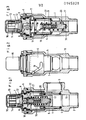
- Fig. 1 eine erfindungsgemäße Absperrarmatur im Vertikalschnitt, und zwar mit geöffnetem Hilfsschließkörper und in Schließstellung befindlichem Ventilschließkörper nach mechanischer Betätigung,
- Fig. 2 den Gegenstand nach Fig. 1 in Offenstellung,
- Fig. 3 den Gegenstand nach Fig. 1 mit in Offenstellung befindlichem Ventilschließkörper, jedoch thermisch geschlossenem Hilfsschließkörper, und
- Fig. 4 eine abgewandelte Ausführungsform nach Fig. 1.
- In den Figuren ist eine Absperrarmatur - beispielsweise Eckarmatur oder Durchflußarmatur - für Gasleitungen dargestellt, die in ihrem grundsätzlichen Aufbau aus einem Armaturengehäuse 1 mit Gaseintrittsstutzen 2 und Gasaustrittsstutzen 3 und mit einem Ventilsitz 4 zwischen Gaseintrittsstutzen 2 und Gasaustrittsstutzen 3 sowie aus einem gegen den Ventilsitz 4 geführten Ventilschließkörper 5 besteht, der mittels einer Betätigungsvorrichtung 6 in Schließstellung überführbar sowie unabhängig von der Betätigungsvorrichtung 6 in Schließstellung beweglich ist, wobei dem Ventilschließkörper 5 eine Dehnstoffpatrone 7 zugeordnet ist und die Dehnstoffpatrone 7 einen axialbeweglichen, koaxial auf den Ventielschließkörper 5 arbeitenden Dehnbolzen 8 aufweist. Die Dehnstoffpatrone 7 ist außerhalb des Armaturengehäuses 1 auf der Betätigungsvorrichtung 6 angeordnet. Die Betätigungsvorrichtung 6 wird in bekannter Weise mit einem Schlüssel 9 betätigt und weist Steuerkurven 10 auf, in welche in den Ventilschließkörper 5 radial eingesetzte Steuerzapfen 11 eingreifen. Die Dehnstoffpatrone 7 ist mittels einer in die Betätigungsvorrichtung 6 bzw. deren Grundkörper einschraubbaren Klemmschraube 12 auf der Betätigungsvorrichtung 6 koaxial zu dem Ventilschließkörper 5 fixierbar. Auf die Dehnstoffpatrone 7 ist ein Wärmeleitkörper 13 aufgesetzt. Der Wärmeleitkörper 13 ist als eine auf die Dehnstoffpatrone aufsteckbare Buchse mit sternartig angeordneten Wärmeleitrippen 14 ausgebildet. Dadurch wird die jeweilige Außentemperatur besonders schnell erfaßt und auf die Dehnstoffpatrone 7 bzw. ihren Dehnstoff übertragen. Die Dehnstoffpatrone 7 und der Wärmeleitkörper 13 sind von einer Schutzkappe 15 aus wärmeleitfähigem Material, beispielsweise Metall, umgeben.
- Der Ventilschließkörper 5 kann mittels einer Rückstellfeder in Offenstellung gehalten und mittels einer Betätigungsvorrichtung gegen Federbeaufschlagung in Schließstellung überführbar sein. Dargestellt ist in den Figuren 1 bis 3 eine Ausführungsform mit einem in dem Ventilschließkörper 5 geführten, in Offenstellung gehaltenen und mit einer Druckfeder 16 beaufschlagten Hilfsschließkörper 17, wobei der Dehnbolzen 8 auf den Hilfsschließkörper 17 arbeitet. Der Hilfsschließkörper 17 ist in Schließrichtung von der Druckfeder 16 beaufschlagt und mittels einer Verriegelungsvorrichtung 18 in Offenstellung gehalten, die bei ausfahrendem Dehnbolzen 8 entriegelt und den Hilfsschließkörper 17 zum Vorschnellen auf seinen Dichtsicht 19 freigibt. Der Hilfsschließkörper 17 ist als Topfzylinder ausgebildet. Die Druckfeder 16 ist zwischen dem Zylinderboden und der Betätigungsvorrichtung mit Vorspannung abgestützt. In dem Zylindertopf ist ein von der Druckfeder 16 umgebender Haltebolzen 20 fixiert. In dem Haltebolzen 20 ist ein entgegen Entriegelungsrichtung federbeaufschlagter Sperrkolben 21 für Verriegelungselemente 22, nämlich Kugeln, der Verriegelungsvorrichtung geführt, wobei der Sperrkolben 21 bei in Offenstellung befindlichem Hilfsschließkörper 17 die Verriegelungselemente 22 in Verriegelungsstellung hält und nach Betätigung durch den ausfahrenden Dehnbolzen 8 der Dehnstoffpatrone 7 in Entriegelungsstellung freigibt. Die Verriegelungselemente 22 greifen in Verriegelungsstellung teilweise in die Betätigungsvorrichtung 6 und teilweise in den Haltebolzen 20 ein, während sie nach Freigabe durch den Sperrkolben 21 hinter dem Sperrkolben vollständig in den Haltebolzen 20 eintreten. - Bei der in Fig. 4 dargestellten Ausführungsform ist der Ventilschließkörper 5 in Schließrichtung von einer Druckfeder 23 beaufschlagt sowie mittels einer Verriegelungsvorrichtung 24 in Offenstellung gehalten, welche bei ausfahrendem Dehnbolzen 8 entriegelt und den Ventilschließkörper 5 zum Vorschnellen auf den Ventilsitz 4 freigibt. Die Verriegelungsvorrichtung 24 ist in einer zentralen Führungsbuchse 25 am Deckel des Armaturengehäuses 1 mit federbeaufschlagtem Sperrkolben 26 und Verriegelungselementen 27 für den Ventilschließkörper 5 angeordnet. Auch in diesem Fall entriegelt der Sperrkolben 26 bei ausfahrendem Dehnbolzen 8 die Verriegelungsvorrichtung 24, so daß dann allerdings der Ventilschließkörper 5 in Schließstellung überführt wird. Diese Ausführungsform kommt also ohne einen Hilfsschließkörper aus.
Claims (11)
Priority Applications (1)
| Application Number | Priority Date | Filing Date | Title |
|---|---|---|---|
| AT84104053T ATE31209T1 (de) | 1983-12-10 | 1984-04-11 | Absperrarmatur fuer gasleitungen. |
Applications Claiming Priority (2)
| Application Number | Priority Date | Filing Date | Title |
|---|---|---|---|
| DE3344704A DE3344704C2 (de) | 1983-12-10 | 1983-12-10 | Absperrarmatur für Gasleitungen |
| DE3344704 | 1983-12-10 |
Publications (3)
| Publication Number | Publication Date |
|---|---|
| EP0145828A2 true EP0145828A2 (de) | 1985-06-26 |
| EP0145828A3 EP0145828A3 (en) | 1986-03-05 |
| EP0145828B1 EP0145828B1 (de) | 1987-12-02 |
Family
ID=6216587
Family Applications (1)
| Application Number | Title | Priority Date | Filing Date |
|---|---|---|---|
| EP84104053A Expired EP0145828B1 (de) | 1983-12-10 | 1984-04-11 | Absperrarmatur für Gasleitungen |
Country Status (3)
| Country | Link |
|---|---|
| EP (1) | EP0145828B1 (de) |
| AT (1) | ATE31209T1 (de) |
| DE (1) | DE3344704C2 (de) |
Cited By (8)
| Publication number | Priority date | Publication date | Assignee | Title |
|---|---|---|---|---|
| EP0257484A1 (de) * | 1986-08-20 | 1988-03-02 | Streif, Hans | Absperrarmatur für insbesondere Gasleitungen |
| EP0365106A3 (en) * | 1988-10-17 | 1990-08-01 | Cameron Iron Works Usa, Inc. (A Delaware Corp.) | Heat sensitive shaft locking apparatus and valve using same |
| EP0655574A1 (de) * | 1993-11-25 | 1995-05-31 | Pyromeca S.A. | Sicherheitsvorrichtung zur Öffnung oder Schliessung eines Schiebers |
| WO1996035899A1 (de) * | 1995-05-09 | 1996-11-14 | Siemens Aktiengesellschaft | Absperrventil |
| FR2736703A1 (fr) * | 1995-07-13 | 1997-01-17 | Pyromeca Sa | Dispositif de fermeture de securite pour vanne, comportant un verin exterieur |
| EP1199501A1 (de) * | 2000-10-20 | 2002-04-24 | Siemens Aktiengesellschaft | Stellantrieb für ein Ventil, insbesondere ein Turbinenventil |
| FR2822220A1 (fr) * | 2001-03-19 | 2002-09-20 | Air Liquide | Robinet de bouteille de gaz a ouverture lente et dispositif d'arret d'urgence |
| EP2587057A1 (de) * | 2011-10-28 | 2013-05-01 | Arquimea Ingenieria, S.L. | Linearschaltvorrichtung |
Families Citing this family (6)
| Publication number | Priority date | Publication date | Assignee | Title |
|---|---|---|---|---|
| DE3817970C1 (de) * | 1988-05-27 | 1989-10-26 | Streif, Hans, Magliaso, Lugano, Ch | |
| DE8812785U1 (de) * | 1988-10-12 | 1988-12-01 | Regel + Meßtechnik GmbH Regler- und Anlagenbau für Gas-Druckregelung, 34123 Kassel | Verschlußeinrichtung für ein Sicherheitsabsperrventil |
| DE4116429A1 (de) * | 1991-05-18 | 1992-11-19 | Vse Vakuumtechn Gmbh | Schnell oeffnendes oder schliessendes ventil |
| DE4422241A1 (de) * | 1994-06-24 | 1996-01-11 | Mertik Maxitrol Gmbh & Co Kg | Thermische Armaturensicherung zum automatischen Absperren von Leitungen |
| DE19608165C1 (de) * | 1996-03-04 | 1997-11-06 | Mertik Maxitrol Gmbh & Co Kg | Thermische Armaturensicherung zum automatischen Absperren von Leitungen |
| DE102016218684B4 (de) | 2016-09-28 | 2019-06-19 | Arianegroup Gmbh | Ventil zum Schließen einer Fluidleitung und Raumfahrzeugantriebssystem |
Family Cites Families (7)
| Publication number | Priority date | Publication date | Assignee | Title |
|---|---|---|---|---|
| GB946275A (en) * | 1962-09-17 | 1964-01-08 | Sulzer Bros London Ltd | Flow regulating valves |
| GB1063090A (en) * | 1963-07-09 | 1967-03-30 | Markaryds Metallarmatur Ab | Improvements in or relating to thermostatic fluid flow valves |
| CH522843A (de) * | 1970-10-06 | 1972-05-15 | Koch Hermann | Thermisches Sicherheitsventil |
| FR2343187A1 (fr) * | 1976-03-05 | 1977-09-30 | Pont A Mousson | Robinet de reglage, notamment pour radiateur |
| IT1051752B (it) * | 1978-02-28 | 1981-05-20 | Bortolan L | Valvola automatica di scarico rapido a elemento termosensibile |
| DE3127545A1 (de) * | 1981-07-11 | 1983-01-20 | Armaturenfabrik und Metallgießerei Koch und Müller GmbH, 4250 Bottrop | Absperrarmatur fuer insbesondere gasleitungen |
| DE8201171U1 (de) * | 1982-01-20 | 1982-06-24 | Armaturenfabrik und Metallgießerei Koch und Müller GmbH, 4250 Bottrop | Absperrarmatur fuer insbesondere gasleitungen |
-
1983
- 1983-12-10 DE DE3344704A patent/DE3344704C2/de not_active Expired
-
1984
- 1984-04-11 AT AT84104053T patent/ATE31209T1/de not_active IP Right Cessation
- 1984-04-11 EP EP84104053A patent/EP0145828B1/de not_active Expired
Cited By (14)
| Publication number | Priority date | Publication date | Assignee | Title |
|---|---|---|---|---|
| EP0257484A1 (de) * | 1986-08-20 | 1988-03-02 | Streif, Hans | Absperrarmatur für insbesondere Gasleitungen |
| EP0365106A3 (en) * | 1988-10-17 | 1990-08-01 | Cameron Iron Works Usa, Inc. (A Delaware Corp.) | Heat sensitive shaft locking apparatus and valve using same |
| EP0655574A1 (de) * | 1993-11-25 | 1995-05-31 | Pyromeca S.A. | Sicherheitsvorrichtung zur Öffnung oder Schliessung eines Schiebers |
| FR2712955A1 (fr) * | 1993-11-25 | 1995-06-02 | Pyromeca | Dispositif de manÓoeuvre d'une vanne à obturateur se déplaçant par translation. |
| FR2712954A1 (fr) * | 1993-11-25 | 1995-06-02 | Pyromeca | Dispositif d'ouverture et de fermeture de sécurité d'une vanne à obturateur se déplaçant par translation. |
| WO1996035899A1 (de) * | 1995-05-09 | 1996-11-14 | Siemens Aktiengesellschaft | Absperrventil |
| FR2736703A1 (fr) * | 1995-07-13 | 1997-01-17 | Pyromeca Sa | Dispositif de fermeture de securite pour vanne, comportant un verin exterieur |
| EP1199501A1 (de) * | 2000-10-20 | 2002-04-24 | Siemens Aktiengesellschaft | Stellantrieb für ein Ventil, insbesondere ein Turbinenventil |
| WO2002035123A1 (de) * | 2000-10-20 | 2002-05-02 | Siemens Aktiengesellschaft | Stellantrieb für ein ventil, insbesondere ein turbinenventil |
| US6915632B2 (en) | 2000-10-20 | 2005-07-12 | Siemens Aktiengesellschaft | Actuator for a valve, in particular a turbine valve |
| FR2822220A1 (fr) * | 2001-03-19 | 2002-09-20 | Air Liquide | Robinet de bouteille de gaz a ouverture lente et dispositif d'arret d'urgence |
| EP1243823A1 (de) * | 2001-03-19 | 2002-09-25 | L'AIR LIQUIDE, Société Anonyme à Directoire et Conseil de Surveillance pour l'Etude et l'Exploitation des | Ventil mit Notabschaltvorrichtung |
| EP2587057A1 (de) * | 2011-10-28 | 2013-05-01 | Arquimea Ingenieria, S.L. | Linearschaltvorrichtung |
| US9206790B2 (en) | 2011-10-28 | 2015-12-08 | Arquimea Ingenieria, S.L.V. | Linear actuator device |
Also Published As
| Publication number | Publication date |
|---|---|
| DE3344704C2 (de) | 1986-09-04 |
| EP0145828B1 (de) | 1987-12-02 |
| DE3344704A1 (de) | 1985-06-20 |
| EP0145828A3 (en) | 1986-03-05 |
| ATE31209T1 (de) | 1987-12-15 |
Similar Documents
| Publication | Publication Date | Title |
|---|---|---|
| EP0145828B1 (de) | Absperrarmatur für Gasleitungen | |
| EP0257484B1 (de) | Absperrarmatur für insbesondere Gasleitungen | |
| EP0701842B1 (de) | Sprühdüse zur Vernebelung von Wasser in Brandschutzanlagen | |
| DE2332895A1 (de) | Vorrichtung zum behandeln von fluessigkeiten und gasen | |
| DE112008000447T5 (de) | Sicherheitsventil | |
| DE1150253B (de) | Rohrbruchsicherung | |
| DE60121505T2 (de) | Ladeventil für Gas | |
| DE2920882A1 (de) | Ventilanordnung | |
| DE3707337A1 (de) | Elektrisches ventil, insbesondere fuer elektrische haushaltsmaschinen, wie waschmaschinen od. dgl. | |
| WO2001081803A1 (de) | Rückschlagventil | |
| DE69208996T2 (de) | System mit Doppelsitz- und Entlüftungsventil | |
| DE69001352T2 (de) | Dichtendes Absperrventil. | |
| DE3127545C2 (de) | ||
| DE3604031C2 (de) | ||
| DE3152977T1 (de) | Schmelzstopfen fuer feuersicheres ventil | |
| DE2627369A1 (de) | Notausloesevorrichtung | |
| DE3817970C1 (de) | ||
| DE2338782B2 (de) | Speicherladeventil | |
| DE102016008106A1 (de) | Tankventil | |
| EP0224825A2 (de) | Hydraulische Blockierfeder | |
| DE19747496C1 (de) | Absperrorgan mit einem Kugelhahn | |
| DE3126213A1 (de) | "absperrarmatur fuer insbesondere gasleitungen" | |
| DE729170C (de) | Sicherheitsvorrichtung fuer Fluessigkeitsbremsen, insbesondere von Kraftfahrzeugen | |
| DE3341123C2 (de) | ||
| DE3606560A1 (de) | Vorrichtung zur zwangsbetaetigung von insbesondere lueftungsklappen |
Legal Events
| Date | Code | Title | Description |
|---|---|---|---|
| PUAI | Public reference made under article 153(3) epc to a published international application that has entered the european phase |
Free format text: ORIGINAL CODE: 0009012 |
|
| AK | Designated contracting states |
Designated state(s): AT BE CH FR GB IT LI NL SE |
|
| PUAL | Search report despatched |
Free format text: ORIGINAL CODE: 0009013 |
|
| RAP1 | Party data changed (applicant data changed or rights of an application transferred) |
Owner name: KOCH, HEINRICH-FRIEDRICH Owner name: KOCH-STOFFERS, ELISABETH-ADELGUNDE |
|
| AK | Designated contracting states |
Kind code of ref document: A3 Designated state(s): AT BE CH FR GB IT LI NL SE |
|
| 17P | Request for examination filed |
Effective date: 19860326 |
|
| 17Q | First examination report despatched |
Effective date: 19870506 |
|
| RAP1 | Party data changed (applicant data changed or rights of an application transferred) |
Owner name: KOCH, HEINRICH-FRIEDRICH Owner name: STREIF, HANS |
|
| GRAA | (expected) grant |
Free format text: ORIGINAL CODE: 0009210 |
|
| RAP1 | Party data changed (applicant data changed or rights of an application transferred) |
Owner name: STREIF, HANS |
|
| AK | Designated contracting states |
Kind code of ref document: B1 Designated state(s): AT BE CH FR GB IT LI NL SE |
|
| REF | Corresponds to: |
Ref document number: 31209 Country of ref document: AT Date of ref document: 19871215 Kind code of ref document: T |
|
| ITF | It: translation for a ep patent filed | ||
| ET | Fr: translation filed | ||
| GBT | Gb: translation of ep patent filed (gb section 77(6)(a)/1977) | ||
| PLBE | No opposition filed within time limit |
Free format text: ORIGINAL CODE: 0009261 |
|
| STAA | Information on the status of an ep patent application or granted ep patent |
Free format text: STATUS: NO OPPOSITION FILED WITHIN TIME LIMIT |
|
| 26N | No opposition filed | ||
| ITTA | It: last paid annual fee | ||
| PGFP | Annual fee paid to national office [announced via postgrant information from national office to epo] |
Ref country code: GB Payment date: 19930322 Year of fee payment: 10 |
|
| PGFP | Annual fee paid to national office [announced via postgrant information from national office to epo] |
Ref country code: FR Payment date: 19930417 Year of fee payment: 10 |
|
| PGFP | Annual fee paid to national office [announced via postgrant information from national office to epo] |
Ref country code: SE Payment date: 19930422 Year of fee payment: 10 Ref country code: AT Payment date: 19930422 Year of fee payment: 10 |
|
| PGFP | Annual fee paid to national office [announced via postgrant information from national office to epo] |
Ref country code: NL Payment date: 19930430 Year of fee payment: 10 |
|
| PGFP | Annual fee paid to national office [announced via postgrant information from national office to epo] |
Ref country code: BE Payment date: 19930504 Year of fee payment: 10 |
|
| PGFP | Annual fee paid to national office [announced via postgrant information from national office to epo] |
Ref country code: CH Payment date: 19930519 Year of fee payment: 10 |
|
| PG25 | Lapsed in a contracting state [announced via postgrant information from national office to epo] |
Ref country code: GB Effective date: 19940411 Ref country code: AT Effective date: 19940411 |
|
| PG25 | Lapsed in a contracting state [announced via postgrant information from national office to epo] |
Ref country code: SE Effective date: 19940412 |
|
| PG25 | Lapsed in a contracting state [announced via postgrant information from national office to epo] |
Ref country code: LI Effective date: 19940430 Ref country code: CH Effective date: 19940430 Ref country code: BE Effective date: 19940430 |
|
| BERE | Be: lapsed |
Owner name: STREIF HANS Effective date: 19940430 |
|
| PG25 | Lapsed in a contracting state [announced via postgrant information from national office to epo] |
Ref country code: NL Effective date: 19941101 |
|
| GBPC | Gb: european patent ceased through non-payment of renewal fee |
Effective date: 19940411 |
|
| NLV4 | Nl: lapsed or anulled due to non-payment of the annual fee | ||
| PG25 | Lapsed in a contracting state [announced via postgrant information from national office to epo] |
Ref country code: FR Effective date: 19941229 |
|
| REG | Reference to a national code |
Ref country code: CH Ref legal event code: PL |
|
| EUG | Se: european patent has lapsed |
Ref document number: 84104053.8 Effective date: 19941110 |
|
| REG | Reference to a national code |
Ref country code: FR Ref legal event code: ST |