EP0145182B1 - Roue volante pour accumuler l'énergie - Google Patents
Roue volante pour accumuler l'énergie Download PDFInfo
- Publication number
- EP0145182B1 EP0145182B1 EP84307143A EP84307143A EP0145182B1 EP 0145182 B1 EP0145182 B1 EP 0145182B1 EP 84307143 A EP84307143 A EP 84307143A EP 84307143 A EP84307143 A EP 84307143A EP 0145182 B1 EP0145182 B1 EP 0145182B1
- Authority
- EP
- European Patent Office
- Prior art keywords
- flywheel
- dished
- rim
- radius
- members
- Prior art date
- Legal status (The legal status is an assumption and is not a legal conclusion. Google has not performed a legal analysis and makes no representation as to the accuracy of the status listed.)
- Expired
Links
Images


Classifications
-
- F—MECHANICAL ENGINEERING; LIGHTING; HEATING; WEAPONS; BLASTING
- F16—ENGINEERING ELEMENTS AND UNITS; GENERAL MEASURES FOR PRODUCING AND MAINTAINING EFFECTIVE FUNCTIONING OF MACHINES OR INSTALLATIONS; THERMAL INSULATION IN GENERAL
- F16C—SHAFTS; FLEXIBLE SHAFTS; ELEMENTS OR CRANKSHAFT MECHANISMS; ROTARY BODIES OTHER THAN GEARING ELEMENTS; BEARINGS
- F16C13/00—Rolls, drums, discs, or the like; Bearings or mountings therefor
-
- F—MECHANICAL ENGINEERING; LIGHTING; HEATING; WEAPONS; BLASTING
- F16—ENGINEERING ELEMENTS AND UNITS; GENERAL MEASURES FOR PRODUCING AND MAINTAINING EFFECTIVE FUNCTIONING OF MACHINES OR INSTALLATIONS; THERMAL INSULATION IN GENERAL
- F16C—SHAFTS; FLEXIBLE SHAFTS; ELEMENTS OR CRANKSHAFT MECHANISMS; ROTARY BODIES OTHER THAN GEARING ELEMENTS; BEARINGS
- F16C15/00—Construction of rotary bodies to resist centrifugal force
-
- F—MECHANICAL ENGINEERING; LIGHTING; HEATING; WEAPONS; BLASTING
- F16—ENGINEERING ELEMENTS AND UNITS; GENERAL MEASURES FOR PRODUCING AND MAINTAINING EFFECTIVE FUNCTIONING OF MACHINES OR INSTALLATIONS; THERMAL INSULATION IN GENERAL
- F16F—SPRINGS; SHOCK-ABSORBERS; MEANS FOR DAMPING VIBRATION
- F16F15/00—Suppression of vibrations in systems; Means or arrangements for avoiding or reducing out-of-balance forces, e.g. due to motion
- F16F15/30—Flywheels
-
- F—MECHANICAL ENGINEERING; LIGHTING; HEATING; WEAPONS; BLASTING
- F16—ENGINEERING ELEMENTS AND UNITS; GENERAL MEASURES FOR PRODUCING AND MAINTAINING EFFECTIVE FUNCTIONING OF MACHINES OR INSTALLATIONS; THERMAL INSULATION IN GENERAL
- F16C—SHAFTS; FLEXIBLE SHAFTS; ELEMENTS OR CRANKSHAFT MECHANISMS; ROTARY BODIES OTHER THAN GEARING ELEMENTS; BEARINGS
- F16C2361/00—Apparatus or articles in engineering in general
- F16C2361/55—Flywheel systems
-
- Y—GENERAL TAGGING OF NEW TECHNOLOGICAL DEVELOPMENTS; GENERAL TAGGING OF CROSS-SECTIONAL TECHNOLOGIES SPANNING OVER SEVERAL SECTIONS OF THE IPC; TECHNICAL SUBJECTS COVERED BY FORMER USPC CROSS-REFERENCE ART COLLECTIONS [XRACs] AND DIGESTS
- Y02—TECHNOLOGIES OR APPLICATIONS FOR MITIGATION OR ADAPTATION AGAINST CLIMATE CHANGE
- Y02E—REDUCTION OF GREENHOUSE GAS [GHG] EMISSIONS, RELATED TO ENERGY GENERATION, TRANSMISSION OR DISTRIBUTION
- Y02E60/00—Enabling technologies; Technologies with a potential or indirect contribution to GHG emissions mitigation
- Y02E60/16—Mechanical energy storage, e.g. flywheels or pressurised fluids
-
- Y—GENERAL TAGGING OF NEW TECHNOLOGICAL DEVELOPMENTS; GENERAL TAGGING OF CROSS-SECTIONAL TECHNOLOGIES SPANNING OVER SEVERAL SECTIONS OF THE IPC; TECHNICAL SUBJECTS COVERED BY FORMER USPC CROSS-REFERENCE ART COLLECTIONS [XRACs] AND DIGESTS
- Y10—TECHNICAL SUBJECTS COVERED BY FORMER USPC
- Y10T—TECHNICAL SUBJECTS COVERED BY FORMER US CLASSIFICATION
- Y10T74/00—Machine element or mechanism
- Y10T74/21—Elements
- Y10T74/2117—Power generating-type flywheel
- Y10T74/2119—Structural detail, e.g., material, configuration, superconductor, discs, laminated, etc.
Definitions
- This invention relates to energy storage flywheels.
- flywheels to accept and discharge energy over relatively short periods of time has been known for many years and energy storage flywheels have been used, or proposed for use, in a variety of applications.
- the amount of energy stored in a flywheel is dependent upon the mass of the flywheel and its rotational speed.
- the maximum amount of energy which can be stored is limited by the materials of construction and the manner in which the stresses which are created are distributed within the flywheel.
- Metals, which have traditionally been used for the manufacture of flywheels, are not as suitable for flywheels which are required to store relatively large amounts of energy in a relatively small space.
- the mass of a metal flywheel and of the necessary containment for the flywheel could negate the advantage of using such an energy storage system in a vehicle.
- the material of construction for a compact, high speed flywheel has a lower density than metal but is at least as strong. Suitable materials are fibre composite materials.
- a suitable flywheel construction is known to comprise a rim which has a relatively high mass mounted on a relatively low mass central portion which is capable of transferring the torque from the hub to the rim and vice versa.
- the central portion may, for example, be a disc or a spider comprising a central hub with radiating spokes.
- US Patent Number 4 266 442 discloses a flywheel comprising a rim which is a circular ring mounted on a central disc portion, the inner radius of the rim being smaller than the outer radius of the disc such that there is an interference fit between the rim and disc of at least 0.001 cm per cm of radius from the centre of the disc to the outer periphery of the rim when the flywheel is at rest.
- the patent discloses a method of making such a flywheel which comprises radially shrinking the flywheel disc by cooling it to a low temperature e.g. 4°K, fitting the rim over the shrunken disc and then expanding the disc to give the required interference fit.
- the flywheel according to the present invention overcomes or at least mitigates the problem of separation of the rim and central portion at high rotational speeds.
- the flywheels according to the invention do not require a large interference fit between the central portion and the rim when the flywheel is at rest and may be assembled without the need to thermally shrink the central portion or to expand the rim.
- Hamamoto JP 58-30548A describes an energy storage flywheel wherein on the outer side of a rotary shaft mounting portion at the centre of a disc the disc thickness is gradually reduced going towards the outer periphery and there are defined plural surfaces which are close to planes normal to said rotary shaft and have mutually different slopes, the outermost periphery of said disc goes via an arcuate curved surface to be formed as a cylinder, a ring made of high-strength carbon fibre reinforced plastic is fixed to the outer periphery of said cylinder and radially directed slits are formed in said disc's outer periphery and said cylinder.
- the present invention overcomes the problems of localised stress and reduced mechanical stiffness that may result from the use of slits in a central disc.
- a flywheel comprising a rim (1) which is a substantially circular ring mounted on a central portion (2) in the form of at least one substantially circular dished member (3) having at least one curved portion the radius of which is such that increasing rotational speed tends to elastically deform the dished member (3), straightening the curve, thereby increasing the diameter of the dished member (3), and the specific modulus of the dished member (3) being less than the specific modulus of the rim (1), characterised in that the dished member (3) is imperforate except for a central hole (5) and comprises three integrally formed, annular portions (6, 7, 8), two of the portions (6, 8) being curved and being positioned at each peripheral margin of the third portion (7) which is curved or straight.
- the central portion of a flywheel according to the present invention comprises two or more co-axial dished members.
- the two or more dished memebrs may be integrally formed but are preferably separate components.
- the dished members are preferably annular and are imperforate apart from the central hole (5).
- the dished members of flywheels according to the present invention may comprise two curved portions, separated by a straight portion, i.e. a portion having an infinite radius.
- the dished members may comprise three curved portions, i.e. each portion has a finite radius, and in this specification the three portions of the dished members will be referred to as 'curved portions'.
- references to the radii of the curved portions refer to the radii of curvature of these portions and not to their radial position in the circular plane of the dished members. The radii are measured to a portion midway through the sectional thickness of the material of the dished members.
- the curved portions will generally be arcs of circles. However, the curved portions may be non-circular curves. If a curve of the curved portions is an ellipsoidal, parabolic or hyperbolic arc, references to the radius of the curved portion should be taken to mean half of the sum of the distances from the focus to each end of the arc.
- the specific modulus of each of the dished members of a flywheel according to the invention i.e. the ratio of the in-plane modulus of the dished memebr to the density of the material of construction of the dished member, is preferably from 25% to 70% of the specific modulus of the rim of the flywheel, i.e. the ratio of the circumferential modulus of the rim to the density of the material of construction of the rim.
- the flywheel illustrated in Figures 1 and 2 comprises a rim (1), which is a substantially circular ring, mounted on a central portion (2).
- the central portion (2) comprises two co-axial, substantially circular dished members (3, 4) each of which has a central hole (5) and comprises three integrally formed curved portions (6,7,8).
- all three of the curved portions (6,7,8) are curved in the same direction. All of the curves are arcs of circles, but as indicated above, the curves may be non-circular.
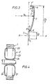
- Figure 3 is a sectional view of part of a dished member drawn on a larger scale.
- the dished member has a similar general shape to the dished members of Figure 2 and the figure illustrates the geometry of the dished members in greater detail.
- the dished members (3, 4) have two annular curved portions which have radii smaller than the third curved portion, the curved portion having the larger radius being positioned between the curved portions of smaller radii.
- the dished members (3, 4) illustrated in Figures 1 to 3 have an annular curved portion (6) with a radius, r 1 , adjacent the periphery of the dished member and an annular curved portion (8) with a radius, r 2 , adjacent the central hole (5) in the dished members; the radii r, and r . being substantially less than the radius r 3 of the annular curved portion 7 which is positioned between curved portions 6 and 8.
- the radii (r,, r 2 , r 3 ) are measured to a position midwaythrough the sectional thickness of the material of the dished members, as shown in Figure 3.
- the radii (r,, r 2 ) of the curved portions (6, 8) adjacent the periphery and the central hole of the dished member may be the same or different and are preferably in the range from 0.02 to 0.2 times the diameter of the dished member (D i ).
- the radius (r 2 ) of the curved portion (8) adjacent the central hole (5) is not less than and is typically not more than 3 times the radius (r 1 ) of the curved portion (6) adjacent the periphery of the dished member.
- the radius (r 3 ) of the third curved portion (7) is preferably in the range from 0.3 to 1.0 times the diameter of the dished member (D I ).
- the periphery of a dished member may tend to move axially when the dished member is rotated at varying speed in the absence of a rim.
- the extent and direction of this axial movement is determined, inter alia, by the relative positions of the centre of curvature (A) of the curved portion (6) adjacent to the periphery of the dished member and the centre of curvature (B) of the curved portion (8) adjacent the central hole (5) in the dished member.
- the centres of curvature (A, B) may both lie on the same plane which plane is perpendicular to the rotational axis of the flywheel.
- the centres of curvature (A, B) lie on different, planes, which planes are perpendicular to the rotational axis of the flywheel.
- An axial displacement of the centres of curvature (A, B) may be used to provide a small net compressive axial force between the dished members (3, 4) and the rim(1).
- a compressive force may be useful, it is necessary to compromise between the benefit obtained by the compressive force and the effect of the additional bending stresses which may be produced within the dished members.
- the diameter D 2 of the central hole (5) in the dished members is selected to enable the flywheel to be mounted on a shaft (9) passing through the central holes of the dished members.
- the radial stiffness of the dished member is affected by the ratio of the diameter of the central hole (D Z ) to the diameter of the dished member (D i ). Typically, this ratio is from 0.2 to 0.6.
- the cross-sectional thickness of the dished members (3, 4) is preferably substantially constant. However, a greater thickness of material may be used around the central hole (5) to facilitate the attachment of the flywheel to a shaft (9). Also additional mass may be provided at the periphery of the dished members to provide an additional force acting radially outwards when the flywheel is rotating. This additional force may assist the increase in the radius (R 1 ) of the dished members when the flywheel is rotated at high speed.
- the dished members (3, 4) should be stiff enough to transfer torque from the rotatable shaft (9) to the rim (1) and vice versa while at the same time being sufficiently flexible in the radial direction to allow the diameter (D 1 ) of the dished members to increase with increasing rotational speed thereby enabling the central portion (2) to remain in contact with the rim (1) over the range of operating speeds of the flywheel.
- This balance of stiffness and flexibility is achieved by the selection of the shape and dimensions of the dished members (3, 4).
- any particular shape of the dished members (3, 4) may be selected according to known engineering principles using for example, finite element analysis.
- the curved portions (6, 7, 8) impart sufficient flexibility in the dished members (3, 4) to enable the diameter (D 1 ) of the dished members to increase with increasing rotational speed.
- the dished members (3,4) should be capable of an increase in diameter (D l ) which is at least equal to the increase in the inner diameter of the rim (1) at the maximum design speed of the flywheel.
- the dished members (3, 4) are capable of an increase in diameter (D i ) which is from 1.15 to 2 times the expected increase in the inner diameter of the rim when rotated at the maximum speed at which the flywheel is to be used.
- the actual increase in the diameter (D l ) of the dished members (3,4) will be constrained by the rim (1) which is more radially stiff than the dished members (3, 4).
- the additional capacity for an increase in the diameter (D l ) provides a safety factor.
- the dished members (3, 4) are preferably manufactured from high strength fibres bonded in a matrix material.
- Suitable high strength fibres include aramid fibres, carbon fibres, or glass fibres.
- Suitable glass fibres include the low alkali borosilicate glass fibres known as E glass.
- Suitable matrix materials include epoxy resins and polyester resins.
- the fibres are in the form of a woven or knitted cloth having good drapability.
- the cloth preferably has substantially equal physical properties in both the warp and weft directions.
- a suitable method of manufacturing the dished members is the resin injection moulding technique.
- a plurality of layers of the fibres are laid out in a mould and the mould closed.
- the matrix material is then injected into the mould filling the voids without substantially displacing the fibres. Injection is stopped when the mould is full and the matrix material is then allowed to cure.
- the dished members preferably have quasi-isotropic properties and so the fibres are preferably arranged in the mould in layers in such a way that the bulk of the fibres of each layer are at an angle to the bulk of the fibres of adjacent layers.
- An alternative method of manufacturing the dished members is to use prepregnated fibres or cloth, i.e.
- the composite material from which the dished members 3 and 4 are made comprises from 40 to 60% by volume of high tensile strength fibres.
- the rim (1) is substantially circular and may, as shown in Figures 1 and 2, comprise a plurality of layers (10, 11, 12).
- the rim (1) is preferably constructed from fibres wound circumferentially and bonded in a suitable matrix material. Suitable materials include, carbon, aramid or glass fibres in epoxy resin or polyester resin. Metal wires e.g. steel wires, bonded in a suitable matrix material may also be suitable. If the rim (1) comprises a plurality of layers then the inner layers preferably have a lower specific modulus than the outer layers so that the radii of the inner layers will tend to increase more than the radii of the outer layers when the flywheel is rotating at a high speed. This arrangement resists separation of the layers at high rotational speed. When the flywheel is at rest, the ratio of the inner radius to the outer radius of the annular rim is preferably from 0.60:1 to 0.85:1.
- the rim (1) and central portion (2) may be manufactured such that the central portion (2) is a sliding fit with the rim (1).
- the central portion may be a tight fit with the rim i.e. there may be a small interference fit between the central portion (2) and the rim.
- the diameter (D 1 ) of the dished members of the central portion (2) is from 0.01% smaller to 0.05% larger than the internal diameter of the rim when the flywheel is at rest. If the central portion (2) has a diameter (D i ) which is initially less than the internal diameter of the rim then means for fixing the central portion to the rim is required. Mechanical fasteners are not used to attach the rim and central portion because such means of attachment may result in undesirable stress concentrations.
- a suitable means of fixing is to use an adhesive such as for example a toughened epoxy resin adhesive. If the diameter (D i ) of the central portion is not less than the internal diameter of the rim (1), then an attachment means such as an adhesive joint may not be required.
- the flywheels according to the present invention do not require a large interference fit and so the flywheels may be assembled without substantially distorting the rim or the central portion and without creating unacceptable levels of stress in the assembled flywheel.
- a relatively small temperature difference, e.g. 20 to 30°C, between the rim (1) and the central portion (2) may be used to facilitate assembly.
- An axial load may be applied around the central hole (5) of the dished members (3, 4) on assembly in order to pre-stress the dished members.
- the whole flywheel expands radially and the inner diameter of the rim increases.
- the centrifugal forces acting on the dished members (3, 4) cause the diameter (Di) of the central portion (2) to increase by elastically deforming the dished members (3, 4).
- the diameter (D 1 ) of the dished members (3, 4) is varied by increases or decreases in the radii of the curved portions (6, 7, 8). This increase in the diameter (D 1 ) of the dished members (3, 4) due to the elastic deformation of the dished members (3, 4) keeps the central portion (2) in contact with the rim.
- the dished portions (3, 4) are less stiff than the rim (1) and so the forces acting on the dished portions (3, 4) to urge them against the inner surface of the rim are not sufficient to substantially deform the rim.
- the shape of the dished members is selected so as to minimise any increase in the diameter (D 2 ) of the central hole (5) in the dished members (3, 4) when the flywheel is rotated at increasing speed.
- the central portion (2) of a flywheel according to the present invention is not attached to the rim (1) by means of a mechanical fastener because such a means of attachement may result in undesirable stress concentrations.
- a force other than a force acting in a radial direction, which is applied to a flywheel of the present invention, may cause the dished members to slip on the inner surface of the rim. Displacement of the dished members with respect to the rim could cause the flywheel to become unbalanced.
- a mechanical interlock may therefore be provided between the rim (1) and the dished members (3, 4). The mechanical interlock should restrict axial movement of the rim with respect to the dished members white not inerfering with their radial movement.
- a suitable mechanical interlock is illustrated in Figure 2 and simply comprises two recesses (13, 14) in the inner surface of the rim with which the outer edges of the dished portions are engaged. If the rim is made of a fibre composite material the recesses (13, 14) are preferably formed during the manufacture of the rim rather than being cut out of the produced article.
- any suitable means may be employed for mounting the flywheel on a rotatable shaft passing through the co-axial central holes in the dished members (3, 4).
- the flywheel may, for example, be clamped to the shaft using suitable retaining means.
- an interference fit may be used to secure the flywheel to the shaft.
- the flywheel illustrated in Figures 1 and 2 is mounted on the rotatable shaft (9) using a sleeve (15) and collars (16, 17).
- the sleeve (15) may be an axially slotted cylinder which has an axially tapered bore corresponding to a tapered portion of the shaft (9).
- Each of the collars (16, 17) comprises a cylinder the outer surface of which engages the dished members (3, 4).
- the collars (16, 17) may have recesses or other forms of mechanical interlock capable of engaging with and resisting axial movement of the dished members (3, 4). Assembling the components and driving the sleeve (15) up the tapered shaft (9) secures the flywheel to the shaft.
- FIGs 4 and 8 are sectional views of alternative embodiments of the flywheel according to the present invention.
- the flywheels of Figure 4 to 6 have dished members with a similar general shape to the dished members of the flywheel illustrated in Figures 1 and 2.
- Figures 7 and 8 illustrate flywheels having dished members with alternative shapes.
- the flywheel illustrated in Figure 4 is similar to the flywheel of Figures 1 and 2 in that it comprises a multi layered rim (1) mounted on a central portion (2).
- the central portion (2) comprises two dished members (20,21) each of which comprises three annular curved portions (22, 23, 24). All of the curved portions are curved in the same direction and are arcs of circles.
- the dished members (20, 21) are positioned with their substantially concave surfaces adjacent rather than having their substantially convex surfaces adjacent as in Figure 2.
- the dished members (20, 21) of Figure 4 are similar to the dished members (3, 4) of Figure 2, they are likely to have a different axial displacement of the centres of curvature of the curved portions 22 and 24.
- FIG 5 is a sectional view of a flywheel which uses four dished members (25, 26, 27, 28) to support the multi-layered rim (1).
- Each of the dished members has a similar general shape to the dished members illustrated in Figures 2 and 4.
- the dished members (25, 26, 27, 28) are arranged in pairs, such that the substantially concave surfaces of each pair are adjacent.
- the rotatable shaft (29) has two tapered portions for ease of assembly.
- FIG. 6 again shows four dished members (30, 31, 32, 33) arranged in pairs to support a multi-layered rim (1).
- each of the dished members is positioned with its substantially convex surface directed towards the centre line C-C of the flywheel.
- Flywheels having only two dished members such as those illustrated in Figures 2 and 4 have the advantage of simplicity.
- the use of more than two dished members provides additional support for the rim.
- the flywheel illustrated in Figure 7 uses two dished members (34, 35) which comprise three curved portions (36, 37, 38), two of which curved portions (36, 37) are curved is the same direction and the third (38) is curved in the opposite direction.
- the curved portions (36, 37, 38) are all arcs of circles.
- the radii of curved portions 36 and 38 are approximately equal and are substantially less than the radius of curved portions 37.
- the flywheel illustrated in Figure 8 uses two dished members (39,40) each of which comprises three annular curved portions (41,42,43). Like the dished members of the flywheel illustrated in Figure 7, two of the curved portions (41, 43) are curved in the same direction while the third (42) is curved in the opposite direction. All of the curved portions are arcs of circles.
- the radii of curved portions 41 and 43 are substantially smaller than the radius of the third curved portion 42, the radius of curved portion 43 being somewhat larger than the radius of curved portion 41.
- Reinforcing rings (44, 45) are shown positioned around the dished members (39, 40) adjacent the central hole in each dished member. Such rings may be used to improve the hoop strength around the central hole (5) in the dished members (39, 40) and may assist in securing the flywheel to the rotatable shaft.
- the reinforcing rings (44, 45) suitably comprise circumferentially wound high strength fibres bonded in a matrix material. Suitable fibres include aramid, carbon and glass fibres and suitable matrix materials include epoxy and polyester resins.
- the rings may be separately formed and positioned on assembly of the flywheel or may be an integrally formed part of the dished members.
- the rings (44, 45) are separately formed, they may be attached to the dished members using any suitable method, e.g. an interference fit.
- An adhesive joint may be used to fix the rings in position.
- Reinforcing rings may be used with any of the flywheels according to the present invention.
- dished members comprising three curved portions
- the dished members may, as indicated hereinbefore, have two curved portions on each side of a straight portion, i.e. a portion of infinite radius.
- dished members having the same general shapes as shown may have straight portions i.e. portions 7, 23, 37 and 42 may be straight.
Landscapes
- Engineering & Computer Science (AREA)
- General Engineering & Computer Science (AREA)
- Mechanical Engineering (AREA)
- Physics & Mathematics (AREA)
- Acoustics & Sound (AREA)
- Aviation & Aerospace Engineering (AREA)
- Turbine Rotor Nozzle Sealing (AREA)
- Connection Of Motors, Electrical Generators, Mechanical Devices, And The Like (AREA)
- Electromechanical Clocks (AREA)
- Braking Arrangements (AREA)
- Portable Nailing Machines And Staplers (AREA)
- Physical Or Chemical Processes And Apparatus (AREA)
- Non-Silver Salt Photosensitive Materials And Non-Silver Salt Photography (AREA)
Claims (12)
Applications Claiming Priority (2)
| Application Number | Priority Date | Filing Date | Title |
|---|---|---|---|
| GB838328295A GB8328295D0 (en) | 1983-10-22 | 1983-10-22 | Energy storage flywheels |
| GB8328295 | 1983-10-22 |
Publications (2)
| Publication Number | Publication Date |
|---|---|
| EP0145182A1 EP0145182A1 (fr) | 1985-06-19 |
| EP0145182B1 true EP0145182B1 (fr) | 1988-05-25 |
Family
ID=10550602
Family Applications (1)
| Application Number | Title | Priority Date | Filing Date |
|---|---|---|---|
| EP84307143A Expired EP0145182B1 (fr) | 1983-10-22 | 1984-10-17 | Roue volante pour accumuler l'énergie |
Country Status (12)
| Country | Link |
|---|---|
| US (1) | US4821599A (fr) |
| EP (1) | EP0145182B1 (fr) |
| JP (1) | JPS60109641A (fr) |
| AU (1) | AU562426B2 (fr) |
| CA (1) | CA1230992A (fr) |
| DE (1) | DE3471509D1 (fr) |
| DK (1) | DK160637C (fr) |
| ES (1) | ES289840Y (fr) |
| GB (1) | GB8328295D0 (fr) |
| IL (1) | IL73276A0 (fr) |
| NO (1) | NO163342C (fr) |
| NZ (1) | NZ209933A (fr) |
Families Citing this family (43)
| Publication number | Priority date | Publication date | Assignee | Title |
|---|---|---|---|---|
| GB8427875D0 (en) * | 1984-11-03 | 1984-12-12 | British Petroleum Co Plc | Storing kinetic energy |
| US5012694A (en) * | 1990-01-29 | 1991-05-07 | The United States Of America As Represented By The Department Of Energy | High speed flywheel |
| JPH0616152U (ja) * | 1992-02-14 | 1994-03-01 | 英輝 金谷 | 自動車 |
| DK70792A (da) * | 1992-05-27 | 1993-11-28 | Risoe Forskningscenter | Svinghjulsindretning |
| NL9201584A (nl) * | 1992-09-11 | 1994-04-05 | Ccm Beheer Bv | Werkwijze voor het met voorspanning bevestigen van een energieopslagvliegwiel op een ondersteuning en klemring te gebruiken bij toepassen van deze werkwijze. |
| FR2705749B1 (fr) * | 1993-05-28 | 1995-07-07 | Renault | Dispositif d'amortissement des vibrations de torsion dans une chaîne de transmission de puissance. |
| JPH09506310A (ja) * | 1993-11-08 | 1997-06-24 | ローゼン・モータース・エル・ピー | 可動エネルギ蓄積用はずみ車装置 |
| US5628232A (en) * | 1994-01-14 | 1997-05-13 | Rosen Motors Lp | Flywheel rotor with conical hub and methods of manufacture therefor |
| US5566588A (en) * | 1994-01-14 | 1996-10-22 | Rosen Motors Lp | Flywheel rotor with conical hub and methods of manufacture therefor |
| US5614777A (en) * | 1995-02-06 | 1997-03-25 | U.S. Flywheel Systems | Flywheel based energy storage system |
| US5760506A (en) * | 1995-06-07 | 1998-06-02 | The Boeing Company | Flywheels for energy storage |
| GB2305993A (en) * | 1995-10-03 | 1997-04-23 | British Nuclear Fuels Plc | An energy storage rotor with axial length compensating means |
| US5720205A (en) * | 1995-12-15 | 1998-02-24 | Harrington; David | Viscous torsional vibration damper with multi-component housing weldment |
| US5732603A (en) * | 1996-03-08 | 1998-03-31 | Hughes Electronics | Flywheel with expansion-matched, self-balancing hub |
| US5778736A (en) * | 1996-06-12 | 1998-07-14 | Dow-United Technologies Composite Products, Inc. | Spiral woven composite flywheel rim |
| US5784926A (en) * | 1996-08-27 | 1998-07-28 | Dow-United Technologies Composite Products, Inc. | Integral composite flywheel rim and hub |
| DE19647513A1 (de) * | 1996-11-16 | 1998-05-20 | Schenck Komeg Gmbh | Rotierbare Schwungscheibenaufnahme |
| JP3763009B2 (ja) * | 1997-04-15 | 2006-04-05 | 弘三 安岡 | 軽重二分割離間はずみ車 |
| US6044726A (en) * | 1997-06-30 | 2000-04-04 | Lockheed Martin Energy Research Corporation | Optimum rotationally symmetric shells for flywheel rotors |
| US6014911A (en) * | 1998-01-13 | 2000-01-18 | Swett; Dwight W. | Flywheel with self-expanding hub |
| JP2000055134A (ja) * | 1998-08-06 | 2000-02-22 | Fuji Heavy Ind Ltd | 複合材フライホイール装置 |
| RU2181170C2 (ru) * | 1999-03-03 | 2002-04-10 | Папук Светлана Николаевна | Маховик со смещенным относительно оси вращения центром масс |
| US7263912B1 (en) * | 1999-08-19 | 2007-09-04 | Toray Composites (America), Inc. | Flywheel hub-to-rim coupling |
| US6633106B1 (en) | 1999-09-30 | 2003-10-14 | Dwight W. Swett | Axial gap motor-generator for high speed operation |
| DE19961643A1 (de) | 1999-12-21 | 2001-06-28 | Canders Wolf R | Schwungrad mit Speichern von Rotationsenergie |
| US6817266B1 (en) | 2000-11-03 | 2004-11-16 | Beacon Power Corporation | Stiff metal hub for an energy storage rotor |
| RU2232929C2 (ru) * | 2001-12-18 | 2004-07-20 | Папук Светлана Николаевна | Маховик со смещенным относительно оси вращения центром масс |
| KR100598846B1 (ko) * | 2004-07-16 | 2006-07-11 | 하성규 | 에너지 저장 시스템의 플라이휠 |
| FR2910738A1 (fr) * | 2006-12-20 | 2008-06-27 | Dominique Mareau | Dispositif de stockage d'energie cinetique en couches cloisonnees |
| US20080168858A1 (en) * | 2007-01-11 | 2008-07-17 | Daniel Bakholdin | Flywheel stability sleeve |
| US8373368B2 (en) * | 2009-02-09 | 2013-02-12 | Ioan Achiriloaie | Energy storage device |
| KR101009715B1 (ko) * | 2010-10-01 | 2011-01-19 | 한양대학교 산학협력단 | 플라이휠용 허브 및 이를 구비한 에너지 저장용 플라이휠 |
| FR2981603B1 (fr) * | 2011-10-25 | 2014-01-17 | Eads Europ Aeronautic Defence | Architecture de roue d'inertie pour le stockage d'energie |
| US9464685B2 (en) | 2013-02-07 | 2016-10-11 | Orbital Atk, Inc. | Composite dome connectors for flywheel rim to shaft attachment |
| GB2504217B (en) | 2013-07-19 | 2016-09-14 | Gkn Hybrid Power Ltd | Flywheels for energy storage and methods of manufacture thereof |
| GB2504218B (en) | 2013-07-19 | 2016-09-14 | Gkn Hybrid Power Ltd | Flywheels for energy storage and methods of manufacture thereof |
| CN103423374B (zh) * | 2013-08-05 | 2015-11-04 | 刘行 | 一种定向做功提速飞轮 |
| NL2012577B1 (en) * | 2014-04-07 | 2016-03-08 | S4 Energy B V | A flywheel system. |
| US10050491B2 (en) | 2014-12-02 | 2018-08-14 | Management Services Group, Inc. | Devices and methods for increasing energy and/or power density in composite flywheel energy storage systems |
| JP6506640B2 (ja) * | 2015-07-02 | 2019-04-24 | 株式会社 エマージー | 回転装置 |
| CN105317924B (zh) * | 2015-11-09 | 2017-08-11 | 清华大学 | 大型变截面无键连接的合金钢惯性储能飞轮 |
| CN105591493A (zh) * | 2016-02-24 | 2016-05-18 | 曾宪林 | 一种飞轮储能转子 |
| EP3460287A4 (fr) * | 2016-04-12 | 2020-03-25 | Kest Gmbh | Volant d'inertie à bande |
Citations (2)
| Publication number | Priority date | Publication date | Assignee | Title |
|---|---|---|---|---|
| DD102781A5 (fr) * | 1972-03-23 | 1973-12-20 | ||
| JPS5830548A (ja) * | 1981-08-19 | 1983-02-23 | Ishikawajima Harima Heavy Ind Co Ltd | エネルギ−貯蔵用フライホイ−ル |
Family Cites Families (21)
| Publication number | Priority date | Publication date | Assignee | Title |
|---|---|---|---|---|
| US422606A (en) * | 1890-03-04 | Manufacture of pulleys | ||
| US1165919A (en) * | 1912-08-05 | 1915-12-28 | Schieble Toy And Novelty Company | Stamped inertia unit. |
| US1265899A (en) * | 1917-07-25 | 1918-05-14 | John C Forster | Fly-wheel. |
| US1451818A (en) * | 1922-07-15 | 1923-04-17 | John C Forster | Gyroscopic top and method of making same |
| US3296886A (en) * | 1965-01-12 | 1967-01-10 | Jr Theodore J Reinhart | Laminated rotary structures |
| US3788162A (en) * | 1972-05-31 | 1974-01-29 | Univ Johns Hopkins | Pseudo-isotropic filament disk structures |
| DE2418831A1 (de) * | 1974-04-19 | 1975-10-30 | Vulkan Kupplung Getriebe | Nachgiebige wellenkupplung |
| DE2540625A1 (de) * | 1975-09-12 | 1977-03-24 | Barmag Barmer Maschf | Vorrichtung zur speicherung kinetischer energie |
| DE2606577A1 (de) * | 1976-02-19 | 1977-08-25 | Barmag Barmer Maschf | Vorrichtung zur speicherung kinetischer energie |
| US4207778A (en) * | 1976-07-19 | 1980-06-17 | General Electric Company | Reinforced cross-ply composite flywheel and method for making same |
| US4102221A (en) * | 1976-07-19 | 1978-07-25 | General Electric Company | Cross-ply composite flywheel |
| US4080845A (en) * | 1976-09-17 | 1978-03-28 | General Electric Company | Shaped disc flywheel |
| SE401548B (sv) * | 1976-09-22 | 1978-05-16 | Volvo Penta Ab | Svenghjul |
| US4176563A (en) * | 1976-10-27 | 1979-12-04 | Electric Power Research Institute | Inertial energy storage rotor with tension-balanced catenary spokes |
| US4370899A (en) * | 1978-09-13 | 1983-02-01 | U.S. Flywheels, Inc. | Flywheel for kinetic energy storage |
| US4341001A (en) * | 1978-09-13 | 1982-07-27 | U.S. Flywheels, Inc. | Hub for use in flywheels for kinetic energy storage |
| SU846889A1 (ru) * | 1979-10-12 | 1981-07-15 | За витель Н.н.Рахманов | Супермаховик |
| US4289251A (en) * | 1980-05-09 | 1981-09-15 | The Continental Group, Inc. | Non-detach easy opening container unit |
| US4660435A (en) * | 1981-05-26 | 1987-04-28 | Rockwell International Corporation | Fiber composite flywheel rim |
| CA1166040A (fr) * | 1981-05-29 | 1984-04-24 | Kenneth T. Ingham | Montage d'un volant d'equilibrage |
| EP0081968A1 (fr) * | 1981-12-11 | 1983-06-22 | The British Petroleum Company p.l.c. | Volant d'inertie accumulateur d'énergie |
-
1983
- 1983-10-22 GB GB838328295A patent/GB8328295D0/en active Pending
-
1984
- 1984-10-17 DE DE8484307143T patent/DE3471509D1/de not_active Expired
- 1984-10-17 EP EP84307143A patent/EP0145182B1/fr not_active Expired
- 1984-10-19 CA CA000465939A patent/CA1230992A/fr not_active Expired
- 1984-10-19 AU AU34504/84A patent/AU562426B2/en not_active Ceased
- 1984-10-19 NO NO844198A patent/NO163342C/no unknown
- 1984-10-19 NZ NZ209933A patent/NZ209933A/en unknown
- 1984-10-21 IL IL73276A patent/IL73276A0/xx unknown
- 1984-10-22 ES ES1984289840U patent/ES289840Y/es not_active Expired
- 1984-10-22 JP JP59220657A patent/JPS60109641A/ja active Pending
- 1984-10-22 DK DK503784A patent/DK160637C/da not_active IP Right Cessation
-
1987
- 1987-09-14 US US07/097,310 patent/US4821599A/en not_active Expired - Fee Related
Patent Citations (2)
| Publication number | Priority date | Publication date | Assignee | Title |
|---|---|---|---|---|
| DD102781A5 (fr) * | 1972-03-23 | 1973-12-20 | ||
| JPS5830548A (ja) * | 1981-08-19 | 1983-02-23 | Ishikawajima Harima Heavy Ind Co Ltd | エネルギ−貯蔵用フライホイ−ル |
Also Published As
| Publication number | Publication date |
|---|---|
| AU3450484A (en) | 1985-11-21 |
| DK503784D0 (da) | 1984-10-22 |
| US4821599A (en) | 1989-04-18 |
| CA1230992A (fr) | 1988-01-05 |
| ES289840Y (es) | 1987-06-16 |
| DE3471509D1 (en) | 1988-06-30 |
| NO163342C (no) | 1990-05-09 |
| IL73276A0 (en) | 1985-01-31 |
| EP0145182A1 (fr) | 1985-06-19 |
| NO844198L (no) | 1985-04-23 |
| ES289840U (es) | 1986-10-16 |
| DK160637C (da) | 1991-09-30 |
| GB8328295D0 (en) | 1983-11-23 |
| JPS60109641A (ja) | 1985-06-15 |
| NZ209933A (en) | 1986-07-11 |
| DK160637B (da) | 1991-04-02 |
| DK503784A (da) | 1985-04-23 |
| NO163342B (no) | 1990-01-05 |
| AU562426B2 (en) | 1987-06-11 |
Similar Documents
| Publication | Publication Date | Title |
|---|---|---|
| EP0145182B1 (fr) | Roue volante pour accumuler l'énergie | |
| US5784926A (en) | Integral composite flywheel rim and hub | |
| EP0081968A1 (fr) | Volant d'inertie accumulateur d'énergie | |
| US4860611A (en) | Energy storage rotor with flexible rim hub | |
| US4207778A (en) | Reinforced cross-ply composite flywheel and method for making same | |
| EP2232098B1 (fr) | Volant | |
| US4266442A (en) | Flywheel including a cross-ply composite core and a relatively thick composite rim | |
| US5816114A (en) | High speed flywheel | |
| US5397272A (en) | Braided composite shaft with yoke member | |
| CA1284279C (fr) | Rotor composite souple d'ultracentrifugeuse | |
| JPS5952307B2 (ja) | はずみ車 | |
| EP0719392B1 (fr) | Dispositif de volant d'inertie a stockage d'energie | |
| US4080845A (en) | Shaped disc flywheel | |
| JPS6025319B2 (ja) | 振動吸収装置 | |
| US7316327B2 (en) | Apparatus and method for reinforcing a pressure vessel | |
| JPH0655456B2 (ja) | 繊維強化樹脂マトリツクス複合材料構造体及びその製造方法 | |
| EP0026570B1 (fr) | Structure centrale pour volants et volants contenant des structures de ce genre | |
| EP0642635B1 (fr) | Dispositif pour volant d'inertie | |
| US9909645B2 (en) | Flywheels for energy storage and methods of manufacture thereof | |
| US4634399A (en) | Structural component for transmitting torque | |
| JPS6241070B2 (fr) | ||
| US6044726A (en) | Optimum rotationally symmetric shells for flywheel rotors | |
| JPS6146695B2 (fr) | ||
| CA1270665A (fr) | Rotor composite d'ultracentrifuge | |
| US11473663B1 (en) | Continuous fiber composite power transfer structures |
Legal Events
| Date | Code | Title | Description |
|---|---|---|---|
| PUAI | Public reference made under article 153(3) epc to a published international application that has entered the european phase |
Free format text: ORIGINAL CODE: 0009012 |
|
| AK | Designated contracting states |
Designated state(s): BE DE FR GB IT NL SE |
|
| 17P | Request for examination filed |
Effective date: 19850719 |
|
| 17Q | First examination report despatched |
Effective date: 19860428 |
|
| ITF | It: translation for a ep patent filed |
Owner name: LENZI & C. |
|
| GRAA | (expected) grant |
Free format text: ORIGINAL CODE: 0009210 |
|
| AK | Designated contracting states |
Kind code of ref document: B1 Designated state(s): BE DE FR GB IT NL SE |
|
| REF | Corresponds to: |
Ref document number: 3471509 Country of ref document: DE Date of ref document: 19880630 |
|
| ET | Fr: translation filed | ||
| PLBE | No opposition filed within time limit |
Free format text: ORIGINAL CODE: 0009261 |
|
| STAA | Information on the status of an ep patent application or granted ep patent |
Free format text: STATUS: NO OPPOSITION FILED WITHIN TIME LIMIT |
|
| 26N | No opposition filed | ||
| PGFP | Annual fee paid to national office [announced via postgrant information from national office to epo] |
Ref country code: NL Payment date: 19931031 Year of fee payment: 10 |
|
| PGFP | Annual fee paid to national office [announced via postgrant information from national office to epo] |
Ref country code: SE Payment date: 19940325 Year of fee payment: 10 |
|
| PGFP | Annual fee paid to national office [announced via postgrant information from national office to epo] |
Ref country code: DE Payment date: 19940327 Year of fee payment: 10 |
|
| PGFP | Annual fee paid to national office [announced via postgrant information from national office to epo] |
Ref country code: GB Payment date: 19940328 Year of fee payment: 10 Ref country code: FR Payment date: 19940328 Year of fee payment: 10 |
|
| PGFP | Annual fee paid to national office [announced via postgrant information from national office to epo] |
Ref country code: BE Payment date: 19940413 Year of fee payment: 10 |
|
| PG25 | Lapsed in a contracting state [announced via postgrant information from national office to epo] |
Ref country code: GB Effective date: 19941017 |
|
| PG25 | Lapsed in a contracting state [announced via postgrant information from national office to epo] |
Ref country code: SE Effective date: 19941018 |
|
| ITTA | It: last paid annual fee | ||
| PG25 | Lapsed in a contracting state [announced via postgrant information from national office to epo] |
Ref country code: BE Effective date: 19941031 |
|
| EAL | Se: european patent in force in sweden |
Ref document number: 84307143.2 |
|
| BERE | Be: lapsed |
Owner name: THE BRITISH PETROLEUM CY P.L.C. Effective date: 19941031 |
|
| PG25 | Lapsed in a contracting state [announced via postgrant information from national office to epo] |
Ref country code: NL Effective date: 19950501 |
|
| GBPC | Gb: european patent ceased through non-payment of renewal fee |
Effective date: 19941017 |
|
| NLV4 | Nl: lapsed or anulled due to non-payment of the annual fee | ||
| PG25 | Lapsed in a contracting state [announced via postgrant information from national office to epo] |
Ref country code: FR Effective date: 19950630 |
|
| PG25 | Lapsed in a contracting state [announced via postgrant information from national office to epo] |
Ref country code: DE Effective date: 19950701 |
|
| EUG | Se: european patent has lapsed |
Ref document number: 84307143.2 |
|
| REG | Reference to a national code |
Ref country code: FR Ref legal event code: ST |