EP0142885B1 - Verfahren zur Herstellung von Bürsten mit Selbstbefestigung der Borsten sowie nach diesem Verfahren hergestellte Bürsten - Google Patents
Verfahren zur Herstellung von Bürsten mit Selbstbefestigung der Borsten sowie nach diesem Verfahren hergestellte Bürsten Download PDFInfo
- Publication number
- EP0142885B1 EP0142885B1 EP84201599A EP84201599A EP0142885B1 EP 0142885 B1 EP0142885 B1 EP 0142885B1 EP 84201599 A EP84201599 A EP 84201599A EP 84201599 A EP84201599 A EP 84201599A EP 0142885 B1 EP0142885 B1 EP 0142885B1
- Authority
- EP
- European Patent Office
- Prior art keywords
- tuft
- brush
- mass
- mold
- bristles
- Prior art date
- Legal status (The legal status is an assumption and is not a legal conclusion. Google has not performed a legal analysis and makes no representation as to the accuracy of the status listed.)
- Expired - Lifetime
Links
Images


Classifications
-
- A—HUMAN NECESSITIES
- A46—BRUSHWARE
- A46D—MANUFACTURE OF BRUSHES
- A46D3/00—Preparing, i.e. Manufacturing brush bodies
-
- A—HUMAN NECESSITIES
- A46—BRUSHWARE
- A46D—MANUFACTURE OF BRUSHES
- A46D3/00—Preparing, i.e. Manufacturing brush bodies
- A46D3/005—Preparing, i.e. Manufacturing brush bodies by moulding or casting a body around bristles or tufts of bristles
-
- A—HUMAN NECESSITIES
- A46—BRUSHWARE
- A46B—BRUSHES
- A46B3/00—Brushes characterised by the way in which the bristles are fixed or joined in or on the brush body or carrier
- A46B3/04—Brushes characterised by the way in which the bristles are fixed or joined in or on the brush body or carrier by mouldable materials, e.g. metals, cellulose derivatives, plastics
-
- A—HUMAN NECESSITIES
- A46—BRUSHWARE
- A46B—BRUSHES
- A46B3/00—Brushes characterised by the way in which the bristles are fixed or joined in or on the brush body or carrier
- A46B3/06—Brushes characterised by the way in which the bristles are fixed or joined in or on the brush body or carrier by welding together bristles made of metal wires or plastic materials
-
- A—HUMAN NECESSITIES
- A46—BRUSHWARE
- A46B—BRUSHES
- A46B5/00—Brush bodies; Handles integral with brushware
-
- A—HUMAN NECESSITIES
- A46—BRUSHWARE
- A46B—BRUSHES
- A46B9/00—Arrangements of the bristles in the brush body
- A46B9/02—Position or arrangement of bristles in relation to surface of the brush body, e.g. inclined, in rows, in groups
- A46B9/04—Arranged like in or for toothbrushes
-
- B—PERFORMING OPERATIONS; TRANSPORTING
- B29—WORKING OF PLASTICS; WORKING OF SUBSTANCES IN A PLASTIC STATE IN GENERAL
- B29C—SHAPING OR JOINING OF PLASTICS; SHAPING OF MATERIAL IN A PLASTIC STATE, NOT OTHERWISE PROVIDED FOR; AFTER-TREATMENT OF THE SHAPED PRODUCTS, e.g. REPAIRING
- B29C45/00—Injection moulding, i.e. forcing the required volume of moulding material through a nozzle into a closed mould; Apparatus therefor
- B29C45/14—Injection moulding, i.e. forcing the required volume of moulding material through a nozzle into a closed mould; Apparatus therefor incorporating preformed parts or layers, e.g. injection moulding around inserts or for coating articles
- B29C45/14336—Coating a portion of the article, e.g. the edge of the article
- B29C45/14385—Coating a portion of a bundle of inserts, e.g. making brushes
-
- A—HUMAN NECESSITIES
- A46—BRUSHWARE
- A46B—BRUSHES
- A46B2200/00—Brushes characterized by their functions, uses or applications
- A46B2200/10—For human or animal care
- A46B2200/1066—Toothbrush for cleaning the teeth or dentures
-
- B—PERFORMING OPERATIONS; TRANSPORTING
- B29—WORKING OF PLASTICS; WORKING OF SUBSTANCES IN A PLASTIC STATE IN GENERAL
- B29C—SHAPING OR JOINING OF PLASTICS; SHAPING OF MATERIAL IN A PLASTIC STATE, NOT OTHERWISE PROVIDED FOR; AFTER-TREATMENT OF THE SHAPED PRODUCTS, e.g. REPAIRING
- B29C45/00—Injection moulding, i.e. forcing the required volume of moulding material through a nozzle into a closed mould; Apparatus therefor
- B29C45/14—Injection moulding, i.e. forcing the required volume of moulding material through a nozzle into a closed mould; Apparatus therefor incorporating preformed parts or layers, e.g. injection moulding around inserts or for coating articles
- B29C45/14336—Coating a portion of the article, e.g. the edge of the article
- B29C45/14385—Coating a portion of a bundle of inserts, e.g. making brushes
- B29C2045/14393—Coating a portion of a bundle of inserts, e.g. making brushes preventing leakage of injected material into tuft insertion holes of the mould
-
- B—PERFORMING OPERATIONS; TRANSPORTING
- B29—WORKING OF PLASTICS; WORKING OF SUBSTANCES IN A PLASTIC STATE IN GENERAL
- B29C—SHAPING OR JOINING OF PLASTICS; SHAPING OF MATERIAL IN A PLASTIC STATE, NOT OTHERWISE PROVIDED FOR; AFTER-TREATMENT OF THE SHAPED PRODUCTS, e.g. REPAIRING
- B29C45/00—Injection moulding, i.e. forcing the required volume of moulding material through a nozzle into a closed mould; Apparatus therefor
- B29C45/14—Injection moulding, i.e. forcing the required volume of moulding material through a nozzle into a closed mould; Apparatus therefor incorporating preformed parts or layers, e.g. injection moulding around inserts or for coating articles
- B29C45/14336—Coating a portion of the article, e.g. the edge of the article
- B29C45/14385—Coating a portion of a bundle of inserts, e.g. making brushes
- B29C2045/14401—Coating a portion of a bundle of inserts, e.g. making brushes using a hot gas for forming a knob on the tuft end
-
- B—PERFORMING OPERATIONS; TRANSPORTING
- B29—WORKING OF PLASTICS; WORKING OF SUBSTANCES IN A PLASTIC STATE IN GENERAL
- B29L—INDEXING SCHEME ASSOCIATED WITH SUBCLASS B29C, RELATING TO PARTICULAR ARTICLES
- B29L2031/00—Other particular articles
- B29L2031/42—Brushes
- B29L2031/425—Toothbrush
Definitions
- This invention relates to brush making and in particular to a method for manufacturing a brush having bristles securely anchored in a molded body, and to brush thus manufactured.
- Stapleless brush making processess have been known since at least 1870, when U.S. Patent 105,373 issued.
- This patent discloses a brush making process in which a molding material is introduced into the cavity of a mold having peforations in one side through which bristle tufts have been inserted such that the looped ends of the tufts project onto the cavity.
- This side of the mold is made of parallel strips which can be separated along the perforations after the molding material forming the brush body has hardened, to facilitate removal of the bristles from the mold side without loosening or extracting the bristles from the body.
- the use of separable strips is an indication of the inability of the molded back to securely hold the bristles.
- Such a separable side is also incompatible with the high pressure injection molding techniques used today for high speed brush production, because the areas between facing surfaces of the strips would provide leakage paths for the injected molding material.
- the ends of the bristle tufts are then inserted into the cavity through the aligned perforations and the molding material is injected around the insert, which becomes an integral part of the brush body. While such inserts might improve bristle retention, they cannot be used in the manufacture of small thin brushes.
- the use of inserts also increases the cost of materials needed to produce brushes, complicates the manufacturing process, and increases the probability of producing defective brushes.
- the inserts must be specially made, means must be provided to position them in the mold cavity and to align their perforations with those in the perforated mold side, and any deformed or misaligned inserts which prevent proper bristle insertion will cause the respective brushes to be rejected.
- heating is effected by bringing an iron into contact with only the very ends of the bristles. Although fusion of the ends of the bristles in this manner might secure individual bristles within a tuft, it does little to improve retention of the tufts themselves.
- DE-C-845 933 discloses a method and apparatus for manufacturing brushes in which each tuft projecting through a hole into the mold cavity is provided at its end with a fused portion having a somewhat larger dimension then the tuft itself. This will improve the retention of the tuft in the molding material but this enlarged fused portion will not close the opening through which the tuft projects into the mold cavity and thus molding material will leak through the holes. This disadvantage in fact adheres to all the methods disclosed by the above documents.
- a brush making process comprises the steps of:
- fusion is defined as the transformation of a substance to a plastic state by heat or other means, including chemical means. Accordingly, fusion of the end of a tuft may be effected by a wide variety of techniques including heat transfer from hot fluid flowing across the end, radiant heat application, exothermic chemical reaction, ultrasonic vibration, and application of a solvent. In a preferred embodiment, fusion is accomplished by electrically heating an inert gas and blowing the heated gas across the end of the tuft.
- the brush making process is simplified and yet produces a new type of brush featuring self-retention of the bristles.
- Injection molding and bristle retention are effectively combined into one operation while eliminating the need for supplementary means for anchoring the bristles in place. Due to the fact that the entire protruding length of the tuft is fused into a mass effective plugging of the hole is obtained and leakage of the molding material is prevented.
- the present invention also provides a brush made in accordance with the above method and comprising an injection molded body and at least one tuft of bristles having an end thereof retained in said body, the said end comprising a fused mass having a cross-sectional area larger than that of the tuft.
- the brush being characterized in that said fused mass is disposed immediately adjacent a face of the body from which the tuft projects, thereby facilitating plugging of a tuft receiving hole in a mold in which the body is formed, said body being molded around said fused mass such that it defines a cavity confor- mig to the shape of the fused mass and having in said face an opening with a cross-sectional area smaller than that of the fused mass, thereby effecting retention of the tuft end in the body.
- the tufts are very securely retained in the body by means of the fused end mass which at the same time during manufacturing provides a plugging of the tuft receiving holes.
- the enlarged fused end mass can have a circular cross-section or an elongated cross-section.
- Figure 1A depicts the insertion of bristle tufts 10 into a pattern of bristle receiving holes 12 formed through an index plate 14 which is shown in section to expose the interiors of some of the holes.
- the index plate 14 is preferably disc-shaped and is mounted to rotate around a central axis (not shown) such that the pattern of bristle receiving holes can be easily indexed from one station to the next during the steps of the brush making process.
- Each of the holes formed through the plate has a widened portion 15 near a front side 16 of the plate to facilitate insertion of the bristle tufts.
- a bristle insertion machine located at a first station inserts the tufts into the holes.
- the tufts can be either precut and fed to the machine, or the machine itself can cut tufts from a bundle of continuous strands of bristle material. If precut tufts are used, they can be either looped at the end to be inserted or cut on both ends, as shown.
- the thickness of the index plate is approximately equal to the desired length of the tufts in the finished brush.
- the tufts 10 should be sufficiently long so that approximately 3 to 5 millimeters protrudes from the back side 18 of the plate after the tufts are pushed into their final positions in the holes.
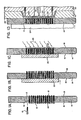
- FIG. 1 B Final positioning is illustrated in Figure 1 B where a backing plate 20 has been pushed against exposed ends of the tufts until they are flush with the front side 16 of the index plate 14.
- the bristle contacting surface of the backing plate can be planar as shown, thus forming the end of each tuft into a flat shape, or it can be configured to form the ends of the tufts into other shapes more suitable to a particular use for which the brush being manufactured is intended.
- Some useful tuft end shapes include the convex, conical and concave shapes shown in Figures 2A, 2B and 2C, respectively.
- This material does not blacken when a flame from a burner utilizing a common gas such as natural gas, propane gas or oxyacetylene is passed across the tuft ends. It is desirable that the ends of the tufts which are heated do not blacken if a transparent molding material is used to form the brush body, because the blackened ends would be visible through the body.
- an inert gas such as nitrogen is heated by passing it through an electric heating coil, and the heated gas is then blown down across the tuft ends until the individual bristles in each tuft end melt together and deform to the ball-shaped mass shown in Figures 3.
- Heated air can also be used, but the temperature of the air and the duration of the heat application to the tuft ends must be more carefully controlled to ensure that they are not heated to their ignition temperature.
- Other fusion techniques which may be utilized include heat radiation, ultrasonic vibration, and the temporary application of a solvent or a hot solution to the tuft ends. Such a solution could be preheated or could be chemical bath undergoing an exothermic reaction.
- the backing plate 20 is withdrawn and the index plate 14 is rotated to an injection molding station as illustrated in Figure 1D, where a clamp plate 24 and a mold part 26 are pressed against opposite sides of the index plate 14.
- the clamp plate 24 functions to support the index plate 145 against the relatively high force applied thereto by the mold part 26 to prevent leakage of injected molding material between the juncture of the plate 14 and part 26.
- the complete mold includes both the portion of the index plate containing the bristles, which forms one side of a mold cavity 28, and the mold part 26, which forms the remainder of the cavity.
- Mold part 26 is itself formed by two separable mold members - a cavity plate 30 and a mold core 32. As is more fully explained below, the part 26 is made separable to facilitate removal of a completed brush.
- a plastic molding material 34 is injected into the cavity through a port 36 with sufficient pressure to fill the cavity and take the form of the brush body. It is during this injection step that the fused masses 22 cooperate with the injected material to both prevent leakage through the tuft receiving holes 12 and to form integral tuft remaining means.
- Figure 4 is an enlarged view of the circled portion of Figure 1 D showing an exemplary one of the fused masses 22 surrounded by molding material 34 which is still in its liquid state.
- the arrows in Figure 4 represent the forces applied to the fused mass by the pressurized molding material and make clear both how the fused mass plugs the hole 12 against leakage and how the respective integral retaining portion of the brush body is formed.
- the forces F 4 , F 6 and F 5 , F 7 respectively, counteract each other, and primarily serve to make the molding material surround the fused mass 22.
- the molding material flows around the fused mass and up to the seal 38, forming an integral tuft retaining structure having a C-shaped cross-section as viewed in Figure 4.
- the entire injection molding step including injection and hardening of the molding material to a degree sufficient to enable removal of the completed brush from the mold, typically takes only about 20 seconds.
- the bristle tufts 10 are removed from the index plate 14 by withdrawing the entire mold part 26 from the index plate, as illustrated in figure 1E.
- the tufts are securely anchored in the hardened plastic material 34 of the brush body by the integral retaining structures formed in the body around the fused masses 22 at the ends of the tufts 10.
- the mold part 26 is then opened, as shown in Figure 1 F, by separating the cavity plate 30 from the mold core 32, enabling ejection of the finished brush from the mold. As illustrated in Figure 1G, ejection is accomplished by using knockout pins 40,42 to push the brush body away from the mold core 32.
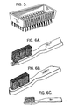
- the finished brush is illustrated in Figure 5.
- Figures 1F and 1G show the index plate 14 still in position at the injection molding station, this plate can be rotated toward the bristling station illustrated in Figure 1A at any time after the bristle tufts are removed from the plate, as illustrated in Figure 1E.
- This and other modifications can be made to increase the production rate.
- a plurality of bristle receiving hole patterns can be provided in the index plate, each moving to a different station as the plate is rotated.
- the finished brush illustrated in Figure 5 looks the same as prior art brushes, unless the places where the bristle tufts enter the brush body are closely examined. Such an examination will show the absence of supplementary bristle retaining means such as the wire staples commonly used in brush making, and it will show an unusually close fit of the body material to the bristle tufts.
- the unique configuration of brushes in accordance with the invention is more readily apparent in Figures 6A, 6B, 6C illustrating a variety of brushes which highlight an additional advantage of the invention. These figures show toothbrushes with bristle tufts having elongated cross-sections.
Claims (5)
Applications Claiming Priority (2)
| Application Number | Priority Date | Filing Date | Title |
|---|---|---|---|
| US55253383A | 1983-11-16 | 1983-11-16 | |
| US552533 | 1983-11-16 |
Publications (3)
| Publication Number | Publication Date |
|---|---|
| EP0142885A2 EP0142885A2 (de) | 1985-05-29 |
| EP0142885A3 EP0142885A3 (en) | 1987-09-02 |
| EP0142885B1 true EP0142885B1 (de) | 1991-02-06 |
Family
ID=24205748
Family Applications (1)
| Application Number | Title | Priority Date | Filing Date |
|---|---|---|---|
| EP84201599A Expired - Lifetime EP0142885B1 (de) | 1983-11-16 | 1984-11-05 | Verfahren zur Herstellung von Bürsten mit Selbstbefestigung der Borsten sowie nach diesem Verfahren hergestellte Bürsten |
Country Status (7)
| Country | Link |
|---|---|
| EP (1) | EP0142885B1 (de) |
| JP (1) | JPH0616725B2 (de) |
| KR (1) | KR910001942B1 (de) |
| AU (1) | AU573644B2 (de) |
| DE (1) | DE3484093D1 (de) |
| HK (1) | HK32893A (de) |
| NO (1) | NO164953C (de) |
Cited By (1)
| Publication number | Priority date | Publication date | Assignee | Title |
|---|---|---|---|---|
| DE19515294B4 (de) * | 1995-04-26 | 2004-04-15 | Zahoransky Formenbau Gmbh | Bürstenherstellungsmaschine |
Families Citing this family (35)
| Publication number | Priority date | Publication date | Assignee | Title |
|---|---|---|---|---|
| DE3511528C1 (de) * | 1985-03-29 | 1991-01-03 | Coronet - Werke Heinrich Schlerf Gmbh, 6948 Wald-Michelbach | Verfahren zur Herstellung von Borstenwaren |
| DE3642124C2 (de) * | 1986-12-10 | 1995-11-23 | Coronet Werke Gmbh | Verfahren zur Herstellung von Borstenwaren und Vorrichtung zur Durchführung des Verfahrens |
| DE3718811C1 (de) * | 1987-06-05 | 1988-03-31 | Schlerf Coronet Werke | Verfahren und Vorrichtung zur Herstellung von Borstenwaren aus Kunststoff |
| DE3820372C2 (de) * | 1988-06-15 | 1997-07-24 | Coronet Werke Gmbh | Verfahren und Vorrichtung zur Herstellung von Borstenwaren |
| ES2071703T3 (es) * | 1990-06-28 | 1995-07-01 | Boucherie Nv G B | Maquina para fabricar cepillos. |
| JP2560181Y2 (ja) * | 1991-10-09 | 1998-01-21 | 大平工業株式会社 | ブラシ |
| US5165761A (en) * | 1991-12-30 | 1992-11-24 | The Procter & Gamble Company | Method of making improved toothbrush having multi-level tufts with substantially uniformly rounded bristle ends in each tuft |
| JPH0650532U (ja) * | 1992-12-21 | 1994-07-12 | ライオン株式会社 | 歯ブラシ |
| DE4302870A1 (de) * | 1993-02-02 | 1994-08-04 | Zahoransky Anton Fa | Verfahren zum Herstellen von Bürsten und Bürstenherstellungsmaschine |
| GB2296184A (en) * | 1993-09-02 | 1996-06-26 | Lingner & Fischer Gmbh | Bristle arrangement for a toothbrush |
| KR100334375B1 (ko) * | 1993-09-02 | 2002-10-18 | 링네어+피셔 게엠베하 | 칫솔에대한칫솔모구성물 |
| DE4415886A1 (de) * | 1994-05-05 | 1995-11-09 | Coronet Werke Gmbh | Verfahren zur Herstellung von Borstenwaren im Wege des Spritzgießens |
| DE19506597A1 (de) * | 1995-02-27 | 1996-08-29 | Coronet Werke Gmbh | Borstenware sowie Verfahren und Vorrichtung zu ihrer Herstellung |
| US6036277A (en) * | 1996-02-14 | 2000-03-14 | Coronet-Werke Gmbh | Method for the manufacture of brushware |
| US5813728A (en) * | 1996-03-07 | 1998-09-29 | Nowiteck Establishment | Process for making rotating brushes for automatic car washes |
| DE19616112A1 (de) * | 1996-04-23 | 1997-10-30 | Coronet Werke Gmbh | Verfahren zur Herstellung von Borstenwaren |
| ES2177106T3 (es) | 1997-10-30 | 2002-12-01 | Schlesinger Maschb Gmbh | Procedimiento y dispositivo para la fabricacion de productos de cerdas. |
| DE19754762C1 (de) * | 1997-11-28 | 1998-12-24 | Stiawa Paul Dipl Oec Ing | Verfahren zur Herstellung von Borstenerzeugnissen unter Nutzung endloser Borstenschnüre |
| EP1056368A2 (de) * | 1998-02-20 | 2000-12-06 | Gillette Canada Company | Zahnbürste und verfahren zum herstellen eines büschels von borsten für eine zahnbürste |
| FI107989B (fi) * | 1998-08-19 | 2001-11-15 | Sajakorpi Oy | Menetelmä ja laitteisto erityisesti metalliharjaksisen harjakiekon valmistukseen |
| DE19853030A1 (de) | 1998-11-18 | 2000-05-25 | Coronet Werke Gmbh | Verfahren zur Herstellung von Borstenwaren und Vorrichtung zur Durchführung des Verfahrens |
| WO2000074917A1 (de) * | 1999-06-02 | 2000-12-14 | M + C Schiffer Gmbh | Verfahren und vorrichtung zur herstellung von bürsten |
| US6352313B1 (en) * | 1999-08-25 | 2002-03-05 | Gillette Canada Company' | Brush tufting |
| DE10017465B4 (de) * | 2000-03-01 | 2010-06-02 | M + C Schiffer Gmbh | Verfahren und Vorrichtung zur Herstellung von Borstenwaren |
| GB0020021D0 (en) | 2000-08-16 | 2000-10-04 | Smithkline Beecham Gmbh & Co | Process |
| DE10217527B4 (de) * | 2002-04-19 | 2012-06-21 | Anton Zahoransky Gmbh & Co. | Verfahren zum Herstellen von Bürsten sowie danach hergestellte Bürste |
| GB0317539D0 (en) | 2003-07-25 | 2003-08-27 | Glaxosmithkline Consumer Healt | Toothbrush |
| KR101203086B1 (ko) | 2004-03-09 | 2012-11-20 | 글락소스미스클라인 컨수머 헬쓰케어 게엠베하 운트 코.카게 | 칫솔 |
| ES2280859T3 (es) | 2004-05-07 | 2007-09-16 | GLAXOSMITHKLINE CONSUMER HEALTHCARE GMBH & CO KG | Cabezal de cepillo. |
| US8202611B2 (en) * | 2004-12-21 | 2012-06-19 | Basell Poliolefine Italia, s.r.l. | Process compositions and permeable films therefrom |
| EP2534974B1 (de) * | 2011-06-15 | 2015-04-29 | Braun GmbH | Verfahren zur Herstellung eines Bürstenkopfs |
| JP2015507987A (ja) | 2012-02-24 | 2015-03-16 | ヴァイカン・エー/エス | 衛生的なブラシヘッド |
| KR101370281B1 (ko) * | 2013-05-22 | 2014-03-06 | 신예현 | 소독성과 세척성이 우수한 실리콘 세척기구 제조장치 및 그 제조방법 |
| DE102016107759A1 (de) * | 2015-07-13 | 2017-01-19 | Gb Boucherie Nv | Verfahren und Vorrichtung zum Herstellen einer Bürste |
| JP6523900B2 (ja) * | 2015-09-28 | 2019-06-05 | 三菱鉛筆株式会社 | ブラシ及びブラシの製造方法 |
Family Cites Families (13)
| Publication number | Priority date | Publication date | Assignee | Title |
|---|---|---|---|---|
| US105373A (en) | 1870-07-12 | Improvement in the manufacture of brushes | ||
| US2317110A (en) | 1938-08-04 | 1943-04-20 | Du Pont | Method of making brushes |
| US2298156A (en) | 1940-12-13 | 1942-10-06 | Du Pont | Manufacture of brushes |
| US2643158A (en) | 1947-06-25 | 1953-06-23 | Columbia Protektosite Co Inc | Method of making molded brushes |
| US2664316A (en) * | 1948-02-05 | 1953-12-29 | Lambert Company | Method of making brushes |
| DE845933C (de) * | 1949-07-28 | 1953-06-11 | Maximilian Schiffer | Verfahren und Maschine zum Herstellen von Buersten, insbesondere von Zahnbuersten |
| GB704590A (en) * | 1952-03-25 | 1954-02-24 | Henry Mortimer | Improved method of making and securing in their ferrules bristle tufts for brushes |
| US3026146A (en) | 1959-12-24 | 1962-03-20 | Szabo Gyozo | Method of and apparatus for the manufacture of brushes |
| FR1453829A (fr) * | 1965-03-05 | 1966-07-22 | Procédé de fabrication de brosses et analogues | |
| US3604043A (en) * | 1969-01-24 | 1971-09-14 | Tucel Industries | Brush and brush constructions |
| US3610692A (en) | 1970-03-03 | 1971-10-05 | Hendrik R Van Der Molen | Apparatus for making brushes |
| JPS5424349B2 (de) * | 1973-06-11 | 1979-08-20 | ||
| JPS5249152B2 (de) * | 1973-07-25 | 1977-12-15 |
-
1984
- 1984-11-05 DE DE8484201599T patent/DE3484093D1/de not_active Expired - Lifetime
- 1984-11-05 EP EP84201599A patent/EP0142885B1/de not_active Expired - Lifetime
- 1984-11-13 NO NO844524A patent/NO164953C/no unknown
- 1984-11-14 JP JP59240403A patent/JPH0616725B2/ja not_active Expired - Fee Related
- 1984-11-14 KR KR1019840007121A patent/KR910001942B1/ko not_active IP Right Cessation
- 1984-11-16 AU AU35499/84A patent/AU573644B2/en not_active Ceased
-
1993
- 1993-04-01 HK HK328/93A patent/HK32893A/xx unknown
Cited By (1)
| Publication number | Priority date | Publication date | Assignee | Title |
|---|---|---|---|---|
| DE19515294B4 (de) * | 1995-04-26 | 2004-04-15 | Zahoransky Formenbau Gmbh | Bürstenherstellungsmaschine |
Also Published As
| Publication number | Publication date |
|---|---|
| KR850003840A (ko) | 1985-06-29 |
| AU573644B2 (en) | 1988-06-16 |
| HK32893A (en) | 1993-04-08 |
| KR910001942B1 (ko) | 1991-03-30 |
| NO164953B (no) | 1990-08-27 |
| JPH0616725B2 (ja) | 1994-03-09 |
| NO844524L (no) | 1985-05-20 |
| EP0142885A3 (en) | 1987-09-02 |
| NO164953C (no) | 1990-12-05 |
| DE3484093D1 (de) | 1991-03-14 |
| EP0142885A2 (de) | 1985-05-29 |
| AU3549984A (en) | 1985-05-23 |
| JPS60116303A (ja) | 1985-06-22 |
Similar Documents
| Publication | Publication Date | Title |
|---|---|---|
| EP0142885B1 (de) | Verfahren zur Herstellung von Bürsten mit Selbstbefestigung der Borsten sowie nach diesem Verfahren hergestellte Bürsten | |
| US4635313A (en) | Brush with self retaining bristles | |
| EP1844677B1 (de) | Verfahren zum herstellen einer zahnbürste | |
| US5474366A (en) | Method of assembling a brush having bristles | |
| US5224763A (en) | Method of fastening bristle tufts to bristle carrier | |
| US4637660A (en) | Method for connecting bristles to a bristle carrier | |
| US4892698A (en) | Method for manufacturing products with bristles | |
| US5609890A (en) | Molding machine for injection molding of tooth brushes | |
| KR20010080485A (ko) | 솔제품의 제조방법 및 이 방법을 실현하는 장치 | |
| KR100465576B1 (ko) | 자동또는수동세차용브러쉬의제조방법 | |
| US20020056941A1 (en) | Method and device for producing brushes | |
| JP3459323B2 (ja) | ブラシの製造方法およびその装置 | |
| JP2003102552A (ja) | 歯ブラシの製造方法 | |
| JP2002086508A (ja) | 射出成形装置 | |
| KR20120056311A (ko) | 칫솔 제조 방법 및 이 방법으로 제조된 칫솔 | |
| CA2251929C (en) | Method for the production of bristle goods | |
| CN114145560B (zh) | 一种刷头组件的制备方法 | |
| CN113453582A (zh) | 制造刷子的方法以及用于执行该方法的刷毛载体和料匣 | |
| JPH0956479A (ja) | ブラシおよびその製造方法 | |
| JPH04348706A (ja) | ブラシの製造方法及びブラシ | |
| US20220240663A1 (en) | Method for Manufacturing a Brush | |
| JPH0956477A (ja) | ブラシ製造方法 | |
| JP2560181Y2 (ja) | ブラシ | |
| JPH09182629A (ja) | ブラシの製造方法およびその装置 | |
| KR100487004B1 (ko) | 브러쉬의제조방법 |
Legal Events
| Date | Code | Title | Description |
|---|---|---|---|
| PUAI | Public reference made under article 153(3) epc to a published international application that has entered the european phase |
Free format text: ORIGINAL CODE: 0009012 |
|
| AK | Designated contracting states |
Designated state(s): BE CH DE FR GB IT LI |
|
| PUAL | Search report despatched |
Free format text: ORIGINAL CODE: 0009013 |
|
| AK | Designated contracting states |
Kind code of ref document: A3 Designated state(s): BE CH DE FR GB IT LI |
|
| 17P | Request for examination filed |
Effective date: 19880301 |
|
| 17Q | First examination report despatched |
Effective date: 19890404 |
|
| GRAA | (expected) grant |
Free format text: ORIGINAL CODE: 0009210 |
|
| AK | Designated contracting states |
Kind code of ref document: B1 Designated state(s): BE CH DE FR GB IT LI |
|
| REF | Corresponds to: |
Ref document number: 3484093 Country of ref document: DE Date of ref document: 19910314 |
|
| ITF | It: translation for a ep patent filed |
Owner name: ING. C. GREGORJ S.P.A. |
|
| ET | Fr: translation filed | ||
| PGFP | Annual fee paid to national office [announced via postgrant information from national office to epo] |
Ref country code: GB Payment date: 19911031 Year of fee payment: 8 |
|
| PGFP | Annual fee paid to national office [announced via postgrant information from national office to epo] |
Ref country code: BE Payment date: 19911113 Year of fee payment: 8 |
|
| PLBI | Opposition filed |
Free format text: ORIGINAL CODE: 0009260 |
|
| PGFP | Annual fee paid to national office [announced via postgrant information from national office to epo] |
Ref country code: FR Payment date: 19911118 Year of fee payment: 8 |
|
| 26 | Opposition filed |
Opponent name: FIRMA CORONET-WERKE, HEINRICH SCHLERF GMBH Effective date: 19911105 |
|
| PGFP | Annual fee paid to national office [announced via postgrant information from national office to epo] |
Ref country code: DE Payment date: 19920127 Year of fee payment: 8 |
|
| PGFP | Annual fee paid to national office [announced via postgrant information from national office to epo] |
Ref country code: CH Payment date: 19920227 Year of fee payment: 8 |
|
| RAP2 | Party data changed (patent owner data changed or rights of a patent transferred) |
Owner name: ANCHOR ADVANCED PRODUCTS, INC. |
|
| PG25 | Lapsed in a contracting state [announced via postgrant information from national office to epo] |
Ref country code: GB Effective date: 19921105 |
|
| PG25 | Lapsed in a contracting state [announced via postgrant information from national office to epo] |
Ref country code: LI Effective date: 19921130 Ref country code: CH Effective date: 19921130 Ref country code: BE Effective date: 19921130 |
|
| BERE | Be: lapsed |
Owner name: NORTH AMERICAN PHILIPS CORP. Effective date: 19921130 |
|
| GBPC | Gb: european patent ceased through non-payment of renewal fee |
Effective date: 19921105 |
|
| PG25 | Lapsed in a contracting state [announced via postgrant information from national office to epo] |
Ref country code: FR Effective date: 19930730 |
|
| REG | Reference to a national code |
Ref country code: CH Ref legal event code: PL |
|
| PG25 | Lapsed in a contracting state [announced via postgrant information from national office to epo] |
Ref country code: DE Effective date: 19930803 |
|
| REG | Reference to a national code |
Ref country code: FR Ref legal event code: ST |
|
| PLAB | Opposition data, opponent's data or that of the opponent's representative modified |
Free format text: ORIGINAL CODE: 0009299OPPO |
|
| R26 | Opposition filed (corrected) |
Opponent name: CORONET-WERKE GMBH Effective date: 19911105 |
|
| PLBN | Opposition rejected |
Free format text: ORIGINAL CODE: 0009273 |
|
| STAA | Information on the status of an ep patent application or granted ep patent |
Free format text: STATUS: OPPOSITION REJECTED |
|
| 27O | Opposition rejected |
Effective date: 19950601 |
|
| APAH | Appeal reference modified |
Free format text: ORIGINAL CODE: EPIDOSCREFNO |