EP0142115A2 - Roue de véhicule automobile - Google Patents
Roue de véhicule automobile Download PDFInfo
- Publication number
- EP0142115A2 EP0142115A2 EP84113337A EP84113337A EP0142115A2 EP 0142115 A2 EP0142115 A2 EP 0142115A2 EP 84113337 A EP84113337 A EP 84113337A EP 84113337 A EP84113337 A EP 84113337A EP 0142115 A2 EP0142115 A2 EP 0142115A2
- Authority
- EP
- European Patent Office
- Prior art keywords
- rim
- tire
- tyre
- vehicle wheel
- bead
- Prior art date
- Legal status (The legal status is an assumption and is not a legal conclusion. Google has not performed a legal analysis and makes no representation as to the accuracy of the status listed.)
- Granted
Links
Images


Classifications
-
- B—PERFORMING OPERATIONS; TRANSPORTING
- B60—VEHICLES IN GENERAL
- B60B—VEHICLE WHEELS; CASTORS; AXLES FOR WHEELS OR CASTORS; INCREASING WHEEL ADHESION
- B60B21/00—Rims
- B60B21/02—Rims characterised by transverse section
- B60B21/021—Rims characterised by transverse section with inwardly directed flanges, i.e. the tyre-seat being reversed
Definitions
- the invention relates to a pneumatic tire vehicle wheel with a rigid rim and with a pneumatic vehicle tire made of rubber or gunmi-like plastics, which has a carcass which is anchored in beads by means of tensile and / or pressure-resistant bead cores, in which the rim laterally outside rim horns and next to these seats for the tire beads and in which the rim is provided on the radially outer side with emergency running support surfaces for the inner wall of the tire.
- Such a vehicle wheel in which the rim flanges extend radially inwards and in which the tire beads are arranged on the radially inner circumference of the rim, has already been proposed.
- a so-called emergency operation mode in which the tire can still be driven to a considerable extent with escaped air without permanent damage.
- the rim has support surfaces on the radially outer side for supporting the tire and in that the tire can bulge sideways outwards so that it does not touch the roadway with its side wall parts in an emergency operation.
- the invention is therefore based on the object of specifying a vehicle wheel of the type mentioned at the outset, in which the tire can be reliably mounted on a one-piece rim which is provided with support surfaces for the tire.
- the rim envelope curve leading through the axis of rotation of the rim has a circumferential length which is at most 0.96 -fold the radially inner circumferential length of the tire in the bead area (inner bead circumference WU) in the mounting position of the tire.
- the rim envelope curve H is to be understood as a curve which takes up a binding thread which is laid tightly around the rim at the largest diameter of the rim transverse to the rim circumferential direction.
- the assembly of a tire insofar as it relates to the introduction of a one-piece rim into the interior of a tire, is considerably simplified.
- An additional simplification in the sense of a lower expenditure of force is achieved in that even before the rim is introduced into the interior of the tire, the tire is brought into an oval shape in its one bead area by external forces.
- the dimensioning specification according to the invention makes it possible to ensure the rim support while ensuring that the tire can be fitted to optimally design the surface in axial and radial extension, so that the emergency running properties of the wheel can be significantly improved again. Furthermore, with the specified design specification, the diameter difference of the rim in the area of the rim flanges and the support surfaces can be optimized, so that on one side the rim flanges are not chosen unnecessarily high, but on the other hand it is ensured that the bead cores behind the rim flanges are sufficient for sufficient throwing resistance dive deep.
- the invention is applicable both to vehicle wheels with a tire attached radially on the inside of the rim and to those in which the tire beads are arranged radially on the outside of the rim.
- the rim and tire are not brought into one another in a parallel position of their axes of rotation, but in a position in which the axes of rotation enclose a relatively large angle, preferably one of approximately 90 ° .
- the vehicle wheel includes a one-piece rigid rim 1 and a tire 2 in which the beads 3 are very far apart.
- the beads 3 In the vulcanizing position, their axial distance is approximately twice the tread width.
- the two beads 3 there are bead cores 4 which can be designed to be tensile and / or pressure-resistant. If necessary, the beads 3 can be designed to be pivotable about the bead core 4. This is particularly necessary for relatively short side walls.
- the side walls 5 and the beads 3 are curved inwards, and the tire 2 is also mounted in this position.
- the rim 1 is moved toward the tire 2 with the axis of rotation according to FIGS. 1 and 2, preferably perpendicular to the axis of rotation of the tire 2, and then inserted into its interior.
- it can be advantageous to deviate from the vertical position of the two axes of rotation.
- a movement of the tire 2 or a movement of both is synonymous with the movement of the rim 1, since only the relative movement is important.
- the insertion of the rim 1 is particularly simple and gentle on the tire if the deformation of the tire 2 is already carried out by external forces before the insertion of the rim 1, for example by clamping the tire by means of a holding device.
- the oval deformation of the tire 2 in its one bead area is particularly good in FIG. 3 can be seen, which represents a top view of tire 2 and rim 1 according to FIG.
- the largest diameter of the rim 1 is also the maximum support surface diameter O ST .
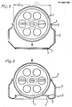
- Fig. 4 shows the fully assembled tire on a one-piece rim 1, the radially inwardly extending rim flanges 6, next to it on the radially inner side of the rim 1 seat 8 for the tire 2, next to mounting recesses 7 and a circumferential on the radially outer side Has support surface 9 for the tire 2.
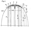
- Fig. 5 the geometric relationships are shown schematically on a tire of the dimension 200/45 R 450 and on a rim of size 135 x 450.
- the inner bead circumference WU of the tire used is 1303 mm (inner bead diameter 415 mm), so that the ratio of the circumferential length of the rim envelope curve to the inner bead circumference has a value of 0.936.
- the table below summarizes test results from tests in which the possibility of fitting three tires of sizes 200/45 R 400, 200/45 R 425 and 200/45 R 450 on rims with nominal diameters 400, 425 and 450 and different inner widths was examined has been.
- the rims all had a support surface diameter D ST that was 35 mm above the nominal diameter D N.
- the value in brackets in the last column "mountable mouth width" means that with the corresponding mouth width the tire is no longer or at most still at risk of tire Damage can be mounted, so that the immediately preceding value indicates the maximum jaw width.
- the penultimate column shows the surprising result that a tire can be fitted to all examined tires and rims if the ratio of rim envelope length H to inner bead circumference WU is less than or equal to 0.96.
Landscapes
- Engineering & Computer Science (AREA)
- Mechanical Engineering (AREA)
- Tires In General (AREA)
- Arrangement Or Mounting Of Propulsion Units For Vehicles (AREA)
- Vehicle Body Suspensions (AREA)
Priority Applications (1)
| Application Number | Priority Date | Filing Date | Title |
|---|---|---|---|
| AT84113337T ATE26949T1 (de) | 1983-11-12 | 1984-11-06 | Fahrzeugrad. |
Applications Claiming Priority (2)
| Application Number | Priority Date | Filing Date | Title |
|---|---|---|---|
| DE3341043 | 1983-11-12 | ||
| DE19833341043 DE3341043A1 (de) | 1983-11-12 | 1983-11-12 | Fahrzeugrad |
Publications (3)
| Publication Number | Publication Date |
|---|---|
| EP0142115A2 true EP0142115A2 (fr) | 1985-05-22 |
| EP0142115A3 EP0142115A3 (en) | 1985-09-11 |
| EP0142115B1 EP0142115B1 (fr) | 1987-05-06 |
Family
ID=6214214
Family Applications (1)
| Application Number | Title | Priority Date | Filing Date |
|---|---|---|---|
| EP84113337A Expired EP0142115B1 (fr) | 1983-11-12 | 1984-11-06 | Roue de véhicule automobile |
Country Status (7)
| Country | Link |
|---|---|
| EP (1) | EP0142115B1 (fr) |
| JP (1) | JPS60174303A (fr) |
| AT (1) | ATE26949T1 (fr) |
| CA (1) | CA1237161A (fr) |
| DE (2) | DE3341043A1 (fr) |
| ES (1) | ES282477Y (fr) |
| GR (1) | GR80875B (fr) |
Cited By (1)
| Publication number | Priority date | Publication date | Assignee | Title |
|---|---|---|---|---|
| EP0217078A1 (fr) * | 1985-08-31 | 1987-04-08 | Continental Aktiengesellschaft | Roue de véhicule pourvue d'un pneumatique |
Families Citing this family (2)
| Publication number | Priority date | Publication date | Assignee | Title |
|---|---|---|---|---|
| DE3541188A1 (de) * | 1985-11-21 | 1987-05-27 | Continental Gummi Werke Ag | Verfahren und vorrichtung zur messung des rundlaufs bei einem fahrzeugluftreifen |
| GB8617729D0 (en) * | 1986-07-19 | 1986-08-28 | Sp Tyres Uk Ltd | Vehicle wheels |
Citations (6)
| Publication number | Priority date | Publication date | Assignee | Title |
|---|---|---|---|---|
| EP0012694A1 (fr) * | 1978-12-15 | 1980-06-25 | MICHELIN & CIE (Compagnie Générale des Etablissements Michelin) Société dite: | Pneumatique à carcasse radiale précontrainte |
| DE3000428A1 (de) * | 1980-01-08 | 1981-07-09 | Continental Gummi-Werke Ag, 3000 Hannover | Fahrzeugrad |
| DE3019742A1 (de) * | 1980-05-23 | 1981-12-10 | Continental Gummi-Werke Ag, 3000 Hannover | Fahrzeugrad |
| AU521469B2 (en) * | 1976-06-04 | 1982-04-01 | Dunlop Limited | Wheel rim for tubless tyre |
| DE3201985A1 (de) * | 1981-02-12 | 1982-10-28 | Michelin & Cie. (Compagnie Générale des Etablissements Michelin), 63040 Clermont-Ferrand | "luftreifen, insbesondere fuer flugzeuge, und verfahren zu seiner herstellung" |
| EP0105204B1 (fr) * | 1982-09-09 | 1986-01-15 | Continental Aktiengesellschaft | Procédé pour le montage d'un pneumatique |
-
1983
- 1983-11-12 DE DE19833341043 patent/DE3341043A1/de not_active Withdrawn
-
1984
- 1984-11-06 DE DE8484113337T patent/DE3463474D1/de not_active Expired
- 1984-11-06 EP EP84113337A patent/EP0142115B1/fr not_active Expired
- 1984-11-06 AT AT84113337T patent/ATE26949T1/de not_active IP Right Cessation
- 1984-11-07 GR GR80875A patent/GR80875B/el unknown
- 1984-11-08 ES ES1984282477U patent/ES282477Y/es not_active Expired
- 1984-11-09 CA CA000467447A patent/CA1237161A/fr not_active Expired
- 1984-11-12 JP JP59236874A patent/JPS60174303A/ja active Pending
Patent Citations (6)
| Publication number | Priority date | Publication date | Assignee | Title |
|---|---|---|---|---|
| AU521469B2 (en) * | 1976-06-04 | 1982-04-01 | Dunlop Limited | Wheel rim for tubless tyre |
| EP0012694A1 (fr) * | 1978-12-15 | 1980-06-25 | MICHELIN & CIE (Compagnie Générale des Etablissements Michelin) Société dite: | Pneumatique à carcasse radiale précontrainte |
| DE3000428A1 (de) * | 1980-01-08 | 1981-07-09 | Continental Gummi-Werke Ag, 3000 Hannover | Fahrzeugrad |
| DE3019742A1 (de) * | 1980-05-23 | 1981-12-10 | Continental Gummi-Werke Ag, 3000 Hannover | Fahrzeugrad |
| DE3201985A1 (de) * | 1981-02-12 | 1982-10-28 | Michelin & Cie. (Compagnie Générale des Etablissements Michelin), 63040 Clermont-Ferrand | "luftreifen, insbesondere fuer flugzeuge, und verfahren zu seiner herstellung" |
| EP0105204B1 (fr) * | 1982-09-09 | 1986-01-15 | Continental Aktiengesellschaft | Procédé pour le montage d'un pneumatique |
Cited By (1)
| Publication number | Priority date | Publication date | Assignee | Title |
|---|---|---|---|---|
| EP0217078A1 (fr) * | 1985-08-31 | 1987-04-08 | Continental Aktiengesellschaft | Roue de véhicule pourvue d'un pneumatique |
Also Published As
| Publication number | Publication date |
|---|---|
| DE3341043A1 (de) | 1985-05-23 |
| CA1237161A (fr) | 1988-05-24 |
| GR80875B (en) | 1985-03-08 |
| ATE26949T1 (de) | 1987-05-15 |
| ES282477Y (es) | 1986-08-01 |
| EP0142115A3 (en) | 1985-09-11 |
| ES282477U (es) | 1986-01-01 |
| DE3463474D1 (en) | 1987-06-11 |
| JPS60174303A (ja) | 1985-09-07 |
| EP0142115B1 (fr) | 1987-05-06 |
Similar Documents
| Publication | Publication Date | Title |
|---|---|---|
| DE3050922C2 (fr) | ||
| DE3711696A1 (de) | Wulstkern fuer einen fahrzeugluftreifen | |
| DE2724996A1 (de) | Luftreifen-felgen-anordnung | |
| DE2714054C3 (de) | Faltbarer Fahrzeugluftreifen auf Tiefbettfelge | |
| EP0156009B1 (fr) | Roue de véhicule automobile | |
| EP0105204B1 (fr) | Procédé pour le montage d'un pneumatique | |
| EP0142115B1 (fr) | Roue de véhicule automobile | |
| DE69933482T2 (de) | Reifen mit abgerundeter Wulstzehe und Form zum Formen des Reifens | |
| DE602006000404T2 (de) | PKW-Reifen | |
| DE112004001518T5 (de) | Reifenradanordnung und Geräuschreduktionsvorrichtung | |
| EP0328873B1 (fr) | Bandage pneumatique pour véhicules | |
| EP0212333B1 (fr) | Roue de véhicule automobile | |
| DE3936231A1 (de) | Kraftwagenreifen | |
| EP0168688A2 (fr) | Roue de véhicule | |
| EP0664228B1 (fr) | Roue à pneumatique d'un véhicule | |
| DE3246624A1 (de) | Fahrzeugluftreifen | |
| DE3420402A1 (de) | Fahrzeugrad | |
| DE1605553A1 (de) | Luftreifen und dazu passende Felge | |
| DE1011303B (de) | Wulsteinlagering fuer einen Luftreifen | |
| DE3343890A1 (de) | Fahrzeugrad | |
| EP0152567A2 (fr) | Roue de véhicule automobile | |
| DE2937272A1 (de) | Luftreifen-radfelgenanordnung | |
| DE1261766B (de) | Fahrzeugrad mit einem vorzugsweise schlauchlosen Luftreifen | |
| EP0146715A2 (fr) | Tringle pour talons de pneumatiques | |
| EP0418762A1 (fr) | Roue de véhicule à pneumatique |
Legal Events
| Date | Code | Title | Description |
|---|---|---|---|
| PUAI | Public reference made under article 153(3) epc to a published international application that has entered the european phase |
Free format text: ORIGINAL CODE: 0009012 |
|
| AK | Designated contracting states |
Designated state(s): AT BE CH DE FR GB IT LI LU NL SE |
|
| PUAL | Search report despatched |
Free format text: ORIGINAL CODE: 0009013 |
|
| AK | Designated contracting states |
Designated state(s): AT BE CH DE FR GB IT LI LU NL SE |
|
| 17P | Request for examination filed |
Effective date: 19850713 |
|
| 17Q | First examination report despatched |
Effective date: 19860922 |
|
| GRAA | (expected) grant |
Free format text: ORIGINAL CODE: 0009210 |
|
| AK | Designated contracting states |
Kind code of ref document: B1 Designated state(s): AT BE CH DE FR GB IT LI LU NL SE |
|
| REF | Corresponds to: |
Ref document number: 26949 Country of ref document: AT Date of ref document: 19870515 Kind code of ref document: T |
|
| ITF | It: translation for a ep patent filed |
Owner name: ING. C. GREGORJ S.P.A. |
|
| REF | Corresponds to: |
Ref document number: 3463474 Country of ref document: DE Date of ref document: 19870611 |
|
| ET | Fr: translation filed | ||
| PG25 | Lapsed in a contracting state [announced via postgrant information from national office to epo] |
Ref country code: LU Free format text: LAPSE BECAUSE OF NON-PAYMENT OF DUE FEES Effective date: 19871130 |
|
| PLBE | No opposition filed within time limit |
Free format text: ORIGINAL CODE: 0009261 |
|
| STAA | Information on the status of an ep patent application or granted ep patent |
Free format text: STATUS: NO OPPOSITION FILED WITHIN TIME LIMIT |
|
| 26N | No opposition filed | ||
| PGFP | Annual fee paid to national office [announced via postgrant information from national office to epo] |
Ref country code: LU Payment date: 19891108 Year of fee payment: 6 |
|
| PGFP | Annual fee paid to national office [announced via postgrant information from national office to epo] |
Ref country code: NL Payment date: 19891130 Year of fee payment: 6 |
|
| PG25 | Lapsed in a contracting state [announced via postgrant information from national office to epo] |
Ref country code: NL Effective date: 19910601 |
|
| NLV4 | Nl: lapsed or anulled due to non-payment of the annual fee | ||
| ITTA | It: last paid annual fee | ||
| PGFP | Annual fee paid to national office [announced via postgrant information from national office to epo] |
Ref country code: CH Payment date: 19931110 Year of fee payment: 10 |
|
| PGFP | Annual fee paid to national office [announced via postgrant information from national office to epo] |
Ref country code: SE Payment date: 19931123 Year of fee payment: 10 |
|
| PGFP | Annual fee paid to national office [announced via postgrant information from national office to epo] |
Ref country code: AT Payment date: 19931130 Year of fee payment: 10 |
|
| PGFP | Annual fee paid to national office [announced via postgrant information from national office to epo] |
Ref country code: BE Payment date: 19931201 Year of fee payment: 10 |
|
| PGFP | Annual fee paid to national office [announced via postgrant information from national office to epo] |
Ref country code: DE Payment date: 19940127 Year of fee payment: 10 |
|
| PG25 | Lapsed in a contracting state [announced via postgrant information from national office to epo] |
Ref country code: AT Effective date: 19941106 |
|
| PG25 | Lapsed in a contracting state [announced via postgrant information from national office to epo] |
Ref country code: SE Effective date: 19941107 |
|
| PG25 | Lapsed in a contracting state [announced via postgrant information from national office to epo] |
Ref country code: LI Effective date: 19941130 Ref country code: CH Effective date: 19941130 Ref country code: BE Effective date: 19941130 |
|
| EAL | Se: european patent in force in sweden |
Ref document number: 84113337.4 |
|
| BERE | Be: lapsed |
Owner name: CONTINENTAL GUMMI-WERKE A.G. Effective date: 19941130 |
|
| REG | Reference to a national code |
Ref country code: CH Ref legal event code: PL |
|
| PG25 | Lapsed in a contracting state [announced via postgrant information from national office to epo] |
Ref country code: DE Effective date: 19950801 |
|
| EUG | Se: european patent has lapsed |
Ref document number: 84113337.4 |
|
| PGFP | Annual fee paid to national office [announced via postgrant information from national office to epo] |
Ref country code: GB Payment date: 19981009 Year of fee payment: 15 |
|
| PGFP | Annual fee paid to national office [announced via postgrant information from national office to epo] |
Ref country code: FR Payment date: 19981126 Year of fee payment: 15 |
|
| PG25 | Lapsed in a contracting state [announced via postgrant information from national office to epo] |
Ref country code: GB Free format text: LAPSE BECAUSE OF NON-PAYMENT OF DUE FEES Effective date: 19991106 |
|
| GBPC | Gb: european patent ceased through non-payment of renewal fee |
Effective date: 19991106 |
|
| PG25 | Lapsed in a contracting state [announced via postgrant information from national office to epo] |
Ref country code: FR Free format text: LAPSE BECAUSE OF NON-PAYMENT OF DUE FEES Effective date: 20000731 |
|
| REG | Reference to a national code |
Ref country code: FR Ref legal event code: ST |