EP0141218A2 - Détecteur pour l'indication des perturbations de réception dans un récepteur M.F. de radio-diffusion - Google Patents
Détecteur pour l'indication des perturbations de réception dans un récepteur M.F. de radio-diffusion Download PDFInfo
- Publication number
- EP0141218A2 EP0141218A2 EP84111154A EP84111154A EP0141218A2 EP 0141218 A2 EP0141218 A2 EP 0141218A2 EP 84111154 A EP84111154 A EP 84111154A EP 84111154 A EP84111154 A EP 84111154A EP 0141218 A2 EP0141218 A2 EP 0141218A2
- Authority
- EP
- European Patent Office
- Prior art keywords
- level
- circuit
- detector according
- detector
- interference
- Prior art date
- Legal status (The legal status is an assumption and is not a legal conclusion. Google has not performed a legal analysis and makes no representation as to the accuracy of the status listed.)
- Granted
Links
Images


Classifications
-
- H—ELECTRICITY
- H04—ELECTRIC COMMUNICATION TECHNIQUE
- H04B—TRANSMISSION
- H04B1/00—Details of transmission systems, not covered by a single one of groups H04B3/00 - H04B13/00; Details of transmission systems not characterised by the medium used for transmission
- H04B1/06—Receivers
- H04B1/10—Means associated with receiver for limiting or suppressing noise or interference
- H04B1/1027—Means associated with receiver for limiting or suppressing noise or interference assessing signal quality or detecting noise/interference for the received signal
Definitions
- the invention relates to a detector for displaying reception interference during FM radio broadcast reception.
- Such detectors are preferably used to improve radio reception in motor vehicles.
- the detector has the task of recognizing and displaying a reception fault.
- a switchover measure is then initiated, which is generally carried out electronically.
- the published patent application DE-A1-3122057 presents a tuner control with a detector for perceiving the signal level in a radio receiver.
- Farther is mentioned in US Pat. No. 3,825,697 of a switchover device which switches from stereo operation to mono operation after detection of a malfunction as a result of the multipath reception. In all of the cases described, a detector is required to detect the fault.
- a disadvantageous basic idea of the present invention resides in the combination of the output signals of a detector for displaying frequency interference and an AM detector for displaying interference amplitude modulation. All previously known detectors for displaying reception interference are limited to evaluating the interference-related amplitude modulation of the frequency-modulated high-frequency carrier. This creates the false indications of reception disorders described above. In systems based on switching between different antennas, this leads to additional reception interference and to long switching times.
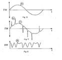
- the inadequacy of the detection of reception interference from the time profile of the carrier amplitude according to the methods known on the filing date can be seen, for example, from the following consideration of the signal-time profiles shown in FIGS. 10 to 12.
- the signal 25 to be transmitted is sinusoidal
- the time profile 25 of the useful frequency swing is likewise sinusoidal in the case of undisturbed transmission, as shown in FIG. 10.
- the antenna moves in the reception wave field, which is composed of a series of superimposed waves from different directions due to multipath propagation with small transit time differences, then a temporal course of the carrier amplitude can occur at the receiver input, as can be seen, for example, from curve 28 in Fig. 12 is shown.
- the RF signal resulting from the superposition of the waves superimposed on Rayleigh does not lead to a distortion in the demodulated signal if the noise level of the receiving system is not fallen below during the drop in amplitude.
- the amplitude modulation shown in FIG. 12 becomes ineffective due to the amplitude limitation before the frequency demodulation. If the transit time difference of the waves overlapping in the wave field exceeds a certain value, then an interference frequency deviation arises depending on the frequency useful stroke and on the amplitude ratios of the superimposed waves, which leads to frequency interference stroke peaks 26, which are represented by curve 27 in FIG. 11.
- FIGS. 11 and 12 it can be seen that at times when frequency interference peaks occur in the distorted signal, an amplitude dip occurs in the curve below.
- This correlation is used by the present invention in order to determine reception disturbances particularly quickly and reliably. From the time course of the amplitude modulation, the occurrence of reception interference cannot be concluded with certainty. This is particularly true in the moving vehicle, where the resulting amplitude modulation depends on the one hand on the movement within a wave field with partial waves with small transit time differences, and on the system-related interference as a result of the superposition of several waves with large transit time differences. With the help of the simultaneous evaluation of frequency interference peaks and the amplitude modulation according to the invention, the display of the reception interference detector is fast and reliable enough to initiate switchover measures sufficiently early in the event of a disturbance.
- both the amplitude of the high-frequency carrier and the instantaneous frequency of the resulting received high-frequency oscillation are falsified at the moment of the interference.
- a disturbance can therefore be reliably recognized by the simultaneous occurrence of amplitude and frequency disturbances.
- a longer observation time of the fault is not necessary for its accurate detection.
- a suitable switchover measure to avoid these receiving errors in the receiving system.
- the detection times for reception disturbances which can be realized with the detector according to the invention for displaying reception disturbances can be reduced to the range of ⁇ s. Switching measures can be derived from this, which, if suitably designed, ensure that audible reception interference is avoided.
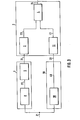
- the 1 shows a detector for displaying reception interference. This consists of a detector 1 for displaying frequency interference, an AM detector 10 for displaying interference amplitude modulation and an evaluation circuit 2 which has two inputs. The possibly disturbed signal on the high or intermediate frequency carrier 21 is fed to both detectors 1 and 10. The two output signals 31 and 33 of these detectors are fed to the evaluation circuit 2 via one input each.
- the evaluation circuit 2 is designed in such a way that the output signal 24 depends both on the interference amplitude modulation of the high-frequency carrier 21 and on its frequency interference stroke.
- the evaluation circuit 2 is designed in such a way that the output signal 24 has a binary character and is designed in such a way that the occurrence of a disturbance is only indicated when both the frequency disturbance stroke and the disturbance amplitude modulation of the received high-frequency or intermediate-frequency signal 21 each exceed a certain threshold.
- the binary decision for the presence of a reception fault is made by a logic circuit 4.
- the exceeding of the interference amplitude modulation or the frequency interference stroke based on suitably set thresholds values, determined.
- a suitable setting of the threshold values is expediently measured at the audibility threshold of the received disturbances.
- the AM detector 10 is designed as an envelope curve demodulator for displaying interference amplitude modulation. It is advisable to choose a frequency bandwidth of the AM detector that is not smaller than the FM channel bandwidth.
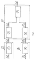
- FIG. 2 shows an advantageous embodiment of the evaluation circuit 2.
- This has a unipolar or bipolar level discriminator 3, to which the output signal 31 of the detector 1 is fed to indicate frequency interference.
- a unipolar level discriminator 11, to which the output signal 33 of the AM detector 10 is fed, is present in the signal branch for determining interference amplitude modulation.
- the output signals 23 and 41 of the two level discriminators 3 and 11 are evaluated by the logic circuit 4 in such a way that the output signal 24 of the evaluation circuit 2 indicates in binary fashion the occurrence of a reception disturbance.
- the output signal 24 only indicates a fault if both thresholds of the level discriminators 3 and 11 are exceeded.
- Reception interference occurs in the output voltages 31 and 33 of the two detectors 1 and 10 in pulse form.
- these pulses are worked out of the rest of the signal with the aid of a circuit which increases the slope of the pulse edges. This leads to a further improvement in the accuracy of the detection of reception problems.
- filters with a high-pass character are provided in the present invention, which do not force a long detection time of the interference by delaying action.
- FIG. 3 shows for the FM detector 1 a circuit 5 which increases the slope of the pulse edges and which is connected downstream of the FM demodulator 8.
- the interference-related pulse peaks in the output signal 31 are therefore larger than the corresponding peaks in the signal 22, the output signal of the FM demodulator 8, and can be more easily separated from the rest of the useful signal by the level discriminator 3.
- a circuit 5 which increases the slope of the pulse edges can be connected downstream of the AM demodulator 18 in a manner similar to that in the branch for detecting frequency interference.
- the interference pulses in the output signal 33 are more strongly emphasized here compared to the amplitude profile, which results from movement of the vehicle in the standing waves in the reception field, than in signal 40, the output signal of the AM demodulator 18. This is shown in FIG. 4 .
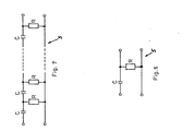
- FIG. 5 shows a combination of the measures according to FIGS. 4 and 3.
- a circuit 5 which increases the slope of the pulse edges can be produced in a particularly simple embodiment by an RC high-pass element.
- the time constant of this RC circuit can be set by selecting the series capacitance and the parallel resistance. This time constant is advantageously set in such a way that the best possible detection of the interference pulses is made possible in the case of the reception disturbances which usually occur.
- Such a differentiator shown in Fig. 6 can be in another Ausge staltung of the invention as an RC chain circuit, as in rig. 7, can be realized.
- the steepness of the pulse edges increases with the number of chain links.
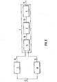
- a unipolar level discriminator 7 and 11 are used both in the branch for determining frequency interference peaks and in the branch for determining interference amplitude modulation.
- a two-way rectifier 9 with the output signal 29 is connected upstream of the unipolar level discriminator 7. Without this two-way rectifier, only interference pulses of one polarity in signal 31 would be evaluated. By additional evaluation of the interference pulses of the other polarity, the security for the detection of the interference can be further increased in a short time.
- the slope of the pulse edge raising circuit 5 is realized by a frequency-dependent network with a high-pass character.
- a circuit can be designed to be frequency-independent.
- a circuit is selected which, in a manner known per se, consists of a power function with even-numbered exponents or a sum of such power functions with the same sign with respect to the relationship between output and input signal, the smallest occurring exponent being greater than the number 1
- the full-wave rectifier 9 can be omitted.
- Such a circuit which increases the slope of the pulse edges, can be assembled in a particularly advantageous manner from semiconductor diode characteristics.
- a circuit is of particular importance, in the context of which there is a hyperbolic cosine function between the output signal and the input signal.
- the logic circuit 4 is designed as an AND gate.
- a unipolar or bipolar level discriminator 3 is used in FIG. 9.
- the output voltage 28 of this circuit 14 increases with the input signals 31 and 33. If the output voltage 28 exceeds the threshold value predetermined in the level discriminator 3, its output signal 23 results in a binary indication of the occurrence of the reception interference.
- the downstream logic circuit 4 could be used for further logical processing of the signal 23.
- the other system components of the detector according to the invention are characterized in claims 17 to 24 with a circuit 14 for analog connection of the output signals 31 and 33.
- the level threshold of the level discriminator or the level discriminators is set dynamically depending on the time-averaged frequency swing.
- This time-averaged frequency deviation can be derived in a manner known per se, for example from the signal 22 at the output of the FM demodulator 8.
- the level threshold is increased accordingly with increasing peaks of this useful frequency swing.
- a detector K em according to the present invention will also indicate the noise as a disturbance in the case of an unfavorable signal-to-noise ratio in the high-frequency channel.
- the level threshold is additionally set depending on the signal-to-noise ratio.
- This setting is designed according to the invention in such a way that if there is pure noise, a reception disturbance is still displayed, so that switchover measures can be carried out with the aid of this detection even when there is no signal. As the signal-to-noise ratio becomes smaller, only the sensitivity of the interference detection is reduced. Since the receiver noise often determines the total noise in the system, the level threshold can be set in a particularly simple embodiment of the invention on the basis of the time-averaged amplitude of the high-frequency carrier.
- the level threshold of the level discriminator 7 or the level discriminators 3 and 11 can be set to be suitable exclusively or additionally as a function of the carrier amplitude averaged over time.
- the level threshold or level thresholds are expediently raised as the carrier amplitude decreases.
Landscapes
- Engineering & Computer Science (AREA)
- Computer Networks & Wireless Communication (AREA)
- Signal Processing (AREA)
- Noise Elimination (AREA)
- Monitoring And Testing Of Transmission In General (AREA)
Applications Claiming Priority (4)
| Application Number | Priority Date | Filing Date | Title |
|---|---|---|---|
| DE19833334735 DE3334735A1 (de) | 1983-09-26 | 1983-09-26 | Detektor zum anzeigen von empfangsstoerungen bei mehrwegeempfang |
| DE3334735 | 1983-09-26 | ||
| JP60015241A JPH0771016B2 (ja) | 1983-09-26 | 1985-01-29 | Uhf−fm放送受信時の受信妨害検出器 |
| US07/009,115 US4777659A (en) | 1983-09-26 | 1987-01-28 | Detector for indicating reception disturbances during ultrashort wave broadcast reception |
Publications (3)
| Publication Number | Publication Date |
|---|---|
| EP0141218A2 true EP0141218A2 (fr) | 1985-05-15 |
| EP0141218A3 EP0141218A3 (en) | 1986-01-08 |
| EP0141218B1 EP0141218B1 (fr) | 1989-05-31 |
Family
ID=27191299
Family Applications (1)
| Application Number | Title | Priority Date | Filing Date |
|---|---|---|---|
| EP84111154A Expired EP0141218B1 (fr) | 1983-09-26 | 1984-09-19 | Détecteur pour l'indication des perturbations de réception dans un récepteur M.F. de radio-diffusion |
Country Status (3)
| Country | Link |
|---|---|
| EP (1) | EP0141218B1 (fr) |
| JP (1) | JPH0771016B2 (fr) |
| DE (2) | DE3334735A1 (fr) |
Cited By (7)
| Publication number | Priority date | Publication date | Assignee | Title |
|---|---|---|---|---|
| EP0201977A2 (fr) * | 1985-05-13 | 1986-11-20 | Koninklijke Philips Electronics N.V. | Dispositif de réception à diversité d'antenne destiné à éliminer des perturbations de réception |
| EP0217475A1 (fr) * | 1985-10-02 | 1987-04-08 | Koninklijke Philips Electronics N.V. | Récepteur comprenant un détecteur de transmission par chemins multiples |
| EP0274157A1 (fr) * | 1986-12-18 | 1988-07-13 | Koninklijke Philips Electronics N.V. | Détecteur modifié de chemins multiples |
| EP0335141A2 (fr) * | 1988-03-26 | 1989-10-04 | Blaupunkt-Werke GmbH | Récepteur radio pour voiture avec circuit pour détecter du bruit de réception locale |
| WO1992002995A1 (fr) * | 1990-07-30 | 1992-02-20 | Richard Hirschmann Gmbh & Co. | Procede pour la reception mobile de signaux stereo multiplex a frequence modulee |
| WO2000031882A1 (fr) * | 1998-11-24 | 2000-06-02 | Robert Bosch Gmbh | Procede et dispositif pour reconnaitre et eliminer des impulsions parasites dans un signal utile |
| CN113067789A (zh) * | 2021-03-25 | 2021-07-02 | 沸蓝建设咨询有限公司 | 一种通信工程特征识别的智能化监测系统 |
Families Citing this family (7)
| Publication number | Priority date | Publication date | Assignee | Title |
|---|---|---|---|---|
| DE3836046A1 (de) * | 1987-10-31 | 1989-05-11 | Hirschmann Radiotechnik | Empfangsverfahren und empfangs-antennensystem zur durchfuehrung des verfahrens |
| DE3802131A1 (de) * | 1988-01-26 | 1989-08-03 | Hirschmann Radiotechnik | Antennensystem fuer den rundfunkempfang in kraftfahrzeugen |
| DE3802130A1 (de) * | 1988-01-26 | 1989-08-03 | Hirschmann Radiotechnik | Antennensystem fuer den rundfunkempfang in kraftfahrzeugen |
| JPH0750860B2 (ja) * | 1988-03-07 | 1995-05-31 | パイオニア株式会社 | Fm受信機におけるパルス性雑音除去装置 |
| DE3814899A1 (de) | 1988-05-03 | 1989-11-16 | Hirschmann Richard Gmbh Co | Empfangsverfahren und empfangs-antennensystem fuer mobilen empfang |
| JPH0750861B2 (ja) * | 1988-08-10 | 1995-05-31 | パイオニア株式会社 | Fm受信機のパルス性ノイズ抑圧装置 |
| DE4008502A1 (de) * | 1990-03-16 | 1991-09-19 | Hirschmann Richard Gmbh Co | Verfahren zum mobilen empfang von digitalen signalen |
Citations (5)
| Publication number | Priority date | Publication date | Assignee | Title |
|---|---|---|---|---|
| DE1282746B (de) * | 1966-10-27 | 1968-11-14 | Telefunken Patent | Empfaenger fuer frequenz-, phasen- oder amplitudenmodulierte Schwingungen mit einer Krachsperre |
| JPS5442913A (en) * | 1977-09-09 | 1979-04-05 | Matsushita Electric Ind Co Ltd | Multi-path detection circuit |
| JPS556972A (en) * | 1978-06-30 | 1980-01-18 | Victor Co Of Japan Ltd | Indicating unit for interference distortion amount of eliminating device for interference distortion occurring in modulation signal due to mutual interference of fm wave signal |
| EP0010552A1 (fr) * | 1978-10-25 | 1980-05-14 | Theodor Tobias Dipl.-Phys. Bossert | Procédé et circuit pour mesurer la qualité de réception d'un signal en ondes ultra-courtes modulé en fréquence |
| JPS58151735A (ja) * | 1982-03-05 | 1983-09-09 | Nippon Telegr & Teleph Corp <Ntt> | 無線干渉検出方式 |
Family Cites Families (3)
| Publication number | Priority date | Publication date | Assignee | Title |
|---|---|---|---|---|
| DE2724376C3 (de) * | 1977-05-28 | 1979-11-15 | Institut Fuer Rundfunktechnik Gmbh, 8000 Muenchen | Verfahren und Einrichtung zum Messen der Empfangsqualität eines frequenzmodulierten UKW-Signals |
| JPS5550746A (en) * | 1978-10-07 | 1980-04-12 | Honda Motor Co Ltd | Noise reduction unit for automobile audio equipment |
| JPS5830338U (ja) * | 1981-08-25 | 1983-02-28 | 横河電機株式会社 | マルチプレクサ駆動回路 |
-
1983
- 1983-09-26 DE DE19833334735 patent/DE3334735A1/de not_active Ceased
-
1984
- 1984-09-19 EP EP84111154A patent/EP0141218B1/fr not_active Expired
- 1984-09-19 DE DE8484111154T patent/DE3478555D1/de not_active Expired
-
1985
- 1985-01-29 JP JP60015241A patent/JPH0771016B2/ja not_active Expired - Lifetime
Patent Citations (5)
| Publication number | Priority date | Publication date | Assignee | Title |
|---|---|---|---|---|
| DE1282746B (de) * | 1966-10-27 | 1968-11-14 | Telefunken Patent | Empfaenger fuer frequenz-, phasen- oder amplitudenmodulierte Schwingungen mit einer Krachsperre |
| JPS5442913A (en) * | 1977-09-09 | 1979-04-05 | Matsushita Electric Ind Co Ltd | Multi-path detection circuit |
| JPS556972A (en) * | 1978-06-30 | 1980-01-18 | Victor Co Of Japan Ltd | Indicating unit for interference distortion amount of eliminating device for interference distortion occurring in modulation signal due to mutual interference of fm wave signal |
| EP0010552A1 (fr) * | 1978-10-25 | 1980-05-14 | Theodor Tobias Dipl.-Phys. Bossert | Procédé et circuit pour mesurer la qualité de réception d'un signal en ondes ultra-courtes modulé en fréquence |
| JPS58151735A (ja) * | 1982-03-05 | 1983-09-09 | Nippon Telegr & Teleph Corp <Ntt> | 無線干渉検出方式 |
Non-Patent Citations (4)
| Title |
|---|
| PATENTS ABSTRACTS OF JAPAN, Band 3, Nr. 64 (E-114), 31. Mai 1979, Seite 113 E114; & JP-A-54 042 913 (MATSUSHITA DENKI SANGYO K.K.) 04.05.1979 * |
| PATENTS ABSTRACTS OF JAPAN, Band 4, Nr. 36 (E-3)(518), 26 März 1980, Seite 23 E 3; & JP - A - 55 6972 & JP - A - 55 6973 * |
| PATENTS ABSTRACTS OF JAPAN, Band 4, Nr. 36 (E-3)(518), 26 März 1980, Seite 23 E 3; & JP-A-55 006 972 (NIPPON VICTOR K.K.) 18.01.1980 & JP - A - 55 6973 (NIIPPON VICTOR K.K.) 18.01.1980 * |
| PATENTS ABSTRACTS OF JAPAN, Band 7, Nr. 272 (E-214)(1417), 3. Dezember 1983; & JP-A-58 151 735 (NIPPON DENSHIN DENWA KOSHA) 09.09.1983 * |
Cited By (11)
| Publication number | Priority date | Publication date | Assignee | Title |
|---|---|---|---|---|
| EP0201977A2 (fr) * | 1985-05-13 | 1986-11-20 | Koninklijke Philips Electronics N.V. | Dispositif de réception à diversité d'antenne destiné à éliminer des perturbations de réception |
| EP0201977A3 (en) * | 1985-05-13 | 1988-08-24 | N.V. Philips' Gloeilampenfabrieken | Antenna diversity reception arrangement for eliminating reception disturbances |
| EP0217475A1 (fr) * | 1985-10-02 | 1987-04-08 | Koninklijke Philips Electronics N.V. | Récepteur comprenant un détecteur de transmission par chemins multiples |
| EP0274157A1 (fr) * | 1986-12-18 | 1988-07-13 | Koninklijke Philips Electronics N.V. | Détecteur modifié de chemins multiples |
| US4878252A (en) * | 1986-12-18 | 1989-10-31 | U. S. Philips Corporation | Modified multi-path detector |
| EP0335141A2 (fr) * | 1988-03-26 | 1989-10-04 | Blaupunkt-Werke GmbH | Récepteur radio pour voiture avec circuit pour détecter du bruit de réception locale |
| EP0335141A3 (fr) * | 1988-03-26 | 1991-08-28 | Blaupunkt-Werke GmbH | Récepteur radio pour voiture avec circuit pour détecter du bruit de réception locale |
| WO1992002995A1 (fr) * | 1990-07-30 | 1992-02-20 | Richard Hirschmann Gmbh & Co. | Procede pour la reception mobile de signaux stereo multiplex a frequence modulee |
| WO2000031882A1 (fr) * | 1998-11-24 | 2000-06-02 | Robert Bosch Gmbh | Procede et dispositif pour reconnaitre et eliminer des impulsions parasites dans un signal utile |
| CN113067789A (zh) * | 2021-03-25 | 2021-07-02 | 沸蓝建设咨询有限公司 | 一种通信工程特征识别的智能化监测系统 |
| CN113067789B (zh) * | 2021-03-25 | 2022-08-02 | 沸蓝建设咨询有限公司 | 一种通信工程特征识别的智能化监测系统 |
Also Published As
| Publication number | Publication date |
|---|---|
| EP0141218B1 (fr) | 1989-05-31 |
| DE3478555D1 (en) | 1989-07-06 |
| JPS61174827A (ja) | 1986-08-06 |
| JPH0771016B2 (ja) | 1995-07-31 |
| DE3334735A1 (de) | 1985-04-18 |
| EP0141218A3 (en) | 1986-01-08 |
Similar Documents
| Publication | Publication Date | Title |
|---|---|---|
| EP0141218B1 (fr) | Détecteur pour l'indication des perturbations de réception dans un récepteur M.F. de radio-diffusion | |
| DE4319457C2 (de) | Schaltungsanordnung zur Nachbarkanalerkennung und -unterdrückung in einem FM-Rundfunkempfänger | |
| DE4208605A1 (de) | Schaltungsanordnung zur nachbarkanalerkennung und -unterdrueckung in einem rundfunkempfaenger | |
| WO2002041537A1 (fr) | Systeme d'antennes | |
| DE3517247A1 (de) | Antennendiversity-empfangsanlage zur elimination von empfangsstoerungen | |
| EP1825602B1 (fr) | Systeme et procede pour determiner un maximum de correlation | |
| EP0132752B1 (fr) | Détecteur pour l'indication des pointes de déviation de fréquence parasitaire | |
| DE10249866B4 (de) | Vorrichtung zur Positionsbestimmung wenigstens einer zweiten Sende- und Empfangseinrichtung bezüglich einer ersten Sende- und Empfangseinrichtung in einem GHz-Bereich arbeitenden passiven Zugangskontrollsystem | |
| DE2921792A1 (de) | Anordnung zur auffindung der anwesenheit schmaler impulse in einem elektrischen signal | |
| DE4338700C2 (de) | Schaltungsanordnung zum Erkennen von Nachbarkanalstörungen in einem Stereo-Multiplex-Rundfunkempfänger | |
| DE3126224C2 (fr) | ||
| US4777659A (en) | Detector for indicating reception disturbances during ultrashort wave broadcast reception | |
| DE2902616C3 (de) | UKW-Empfänger, insbesondere Autoempfänger, mit feldstärkeabhängiger Lautstärkesteuerung | |
| EP1525729A1 (fr) | Dispositif de reception pour un signal radio | |
| DE3138395C2 (fr) | ||
| DE19722385C2 (de) | Verfahren zur Erkennung von Multipathstörungen beim FM-Rundfunkempfang und Schaltungsanordnung zur Durchführung des Verfahrens | |
| DE3211104A1 (de) | Verfahren und anordnung zur automatischen erkennung eines nachrichtensignals | |
| DE3400859A1 (de) | Automatisches sendersuchverfahren und suchempfaenger zur durchfuehrung des verfahrens | |
| EP0824818B1 (fr) | Production d'un signal de commande de frequence dans un recepteur a gamme de frequences | |
| DE1290605B (de) | Anordnung zur Feststellung der zeitlichen Lage des Halbwertpunktes der Anstiegsflanke eines Impulses in einem Transponder zur Entfernungsabfrage bei Funknavigationsanlagen | |
| WO1993015568A1 (fr) | Procede pour la generation d'un signal indiquant les brouillages par un canal adjacent | |
| DE3040854C2 (fr) | ||
| DE2600687A1 (de) | Schaltung zur vergleichenden vektormessung von bei mehreren empfaengern nahezu gleichzeitig eintreffenden funksignalimpulsen | |
| EP2677663B1 (fr) | Squelch de niveau avec une immunité élevée contre les interférences d'impulsions | |
| DE2517389C2 (de) | Anordnung zum Umschalten der Empfindlichkeit von Empfangsgeräten |
Legal Events
| Date | Code | Title | Description |
|---|---|---|---|
| PUAI | Public reference made under article 153(3) epc to a published international application that has entered the european phase |
Free format text: ORIGINAL CODE: 0009012 |
|
| AK | Designated contracting states |
Designated state(s): DE FR GB IT NL SE |
|
| PUAL | Search report despatched |
Free format text: ORIGINAL CODE: 0009013 |
|
| AK | Designated contracting states |
Designated state(s): DE FR GB IT NL SE |
|
| 17P | Request for examination filed |
Effective date: 19860701 |
|
| RAP1 | Party data changed (applicant data changed or rights of an application transferred) |
Owner name: N.V. PHILIPS' GLOEILAMPENFABRIEKEN Owner name: HANS KOLBE & CO. |
|
| 17Q | First examination report despatched |
Effective date: 19871126 |
|
| GRAA | (expected) grant |
Free format text: ORIGINAL CODE: 0009210 |
|
| AK | Designated contracting states |
Kind code of ref document: B1 Designated state(s): DE FR GB IT NL SE |
|
| REF | Corresponds to: |
Ref document number: 3478555 Country of ref document: DE Date of ref document: 19890706 |
|
| ITF | It: translation for a ep patent filed |
Owner name: ING. C. GREGORJ S.P.A. |
|
| ET | Fr: translation filed | ||
| GBT | Gb: translation of ep patent filed (gb section 77(6)(a)/1977) | ||
| PLBE | No opposition filed within time limit |
Free format text: ORIGINAL CODE: 0009261 |
|
| STAA | Information on the status of an ep patent application or granted ep patent |
Free format text: STATUS: NO OPPOSITION FILED WITHIN TIME LIMIT |
|
| 26N | No opposition filed | ||
| ITTA | It: last paid annual fee | ||
| EAL | Se: european patent in force in sweden |
Ref document number: 84111154.5 |
|
| ITPR | It: changes in ownership of a european patent |
Owner name: CAMBIO RAGIONE SOCIALE;PHILIPS ELECTRONICS N.V. |
|
| REG | Reference to a national code |
Ref country code: FR Ref legal event code: CD |
|
| NLT1 | Nl: modifications of names registered in virtue of documents presented to the patent office pursuant to art. 16 a, paragraph 1 |
Owner name: PHILIPS ELECTRONICS N.V. |
|
| REG | Reference to a national code |
Ref country code: GB Ref legal event code: 732E |
|
| REG | Reference to a national code |
Ref country code: FR Ref legal event code: TP |
|
| NLS | Nl: assignments of ep-patents |
Owner name: PHILIPS ELECTRONICS N.V.;FUBA AUTOMOTIVE GMBH |
|
| NLT1 | Nl: modifications of names registered in virtue of documents presented to the patent office pursuant to art. 16 a, paragraph 1 |
Owner name: HANS KOLBE & CO.;PHILIPS ELECTRONICS N.V. |
|
| NLT1 | Nl: modifications of names registered in virtue of documents presented to the patent office pursuant to art. 16 a, paragraph 1 |
Owner name: KONINKLIJKE PHILIPS ELECTRONICS N.V.;FUBA AUTOMOTI |
|
| REG | Reference to a national code |
Ref country code: FR Ref legal event code: CD |
|
| REG | Reference to a national code |
Ref country code: FR Ref legal event code: TQ |
|
| NLS | Nl: assignments of ep-patents |
Owner name: FUBA AUTOMOTIVE GMBH |
|
| REG | Reference to a national code |
Ref country code: GB Ref legal event code: IF02 |
|
| PGFP | Annual fee paid to national office [announced via postgrant information from national office to epo] |
Ref country code: SE Payment date: 20030904 Year of fee payment: 20 |
|
| PGFP | Annual fee paid to national office [announced via postgrant information from national office to epo] |
Ref country code: FR Payment date: 20030909 Year of fee payment: 20 |
|
| PGFP | Annual fee paid to national office [announced via postgrant information from national office to epo] |
Ref country code: GB Payment date: 20030917 Year of fee payment: 20 |
|
| PGFP | Annual fee paid to national office [announced via postgrant information from national office to epo] |
Ref country code: NL Payment date: 20030922 Year of fee payment: 20 |
|
| PGFP | Annual fee paid to national office [announced via postgrant information from national office to epo] |
Ref country code: DE Payment date: 20031002 Year of fee payment: 20 |
|
| PG25 | Lapsed in a contracting state [announced via postgrant information from national office to epo] |
Ref country code: GB Free format text: LAPSE BECAUSE OF EXPIRATION OF PROTECTION Effective date: 20040918 |
|
| PG25 | Lapsed in a contracting state [announced via postgrant information from national office to epo] |
Ref country code: NL Free format text: LAPSE BECAUSE OF EXPIRATION OF PROTECTION Effective date: 20040919 |
|
| REG | Reference to a national code |
Ref country code: GB Ref legal event code: PE20 |
|
| NLV7 | Nl: ceased due to reaching the maximum lifetime of a patent |
Effective date: 20040919 |
|
| EUG | Se: european patent has lapsed |