EP0140756B2 - Dispositif d'entraînement des câbles d'une installation de transport à câbles aériens - Google Patents
Dispositif d'entraînement des câbles d'une installation de transport à câbles aériens Download PDFInfo
- Publication number
- EP0140756B2 EP0140756B2 EP84401920A EP84401920A EP0140756B2 EP 0140756 B2 EP0140756 B2 EP 0140756B2 EP 84401920 A EP84401920 A EP 84401920A EP 84401920 A EP84401920 A EP 84401920A EP 0140756 B2 EP0140756 B2 EP 0140756B2
- Authority
- EP
- European Patent Office
- Prior art keywords
- motors
- cables
- cable
- armature
- coupled
- Prior art date
- Legal status (The legal status is an assumption and is not a legal conclusion. Google has not performed a legal analysis and makes no representation as to the accuracy of the status listed.)
- Expired - Lifetime
Links
- 230000005284 excitation Effects 0.000 claims abstract description 5
- 238000004804 winding Methods 0.000 claims abstract 3
- 238000009434 installation Methods 0.000 claims description 10
- 239000000725 suspension Substances 0.000 abstract 1
- 239000003638 chemical reducing agent Substances 0.000 description 3
- 230000001360 synchronised effect Effects 0.000 description 3
- 230000005540 biological transmission Effects 0.000 description 2
- 230000008878 coupling Effects 0.000 description 2
- 238000010168 coupling process Methods 0.000 description 2
- 238000005859 coupling reaction Methods 0.000 description 2
- 238000010586 diagram Methods 0.000 description 2
- 230000001105 regulatory effect Effects 0.000 description 2
- 230000033228 biological regulation Effects 0.000 description 1
- 239000000969 carrier Substances 0.000 description 1
- 230000007423 decrease Effects 0.000 description 1
- 239000006185 dispersion Substances 0.000 description 1
- 238000005259 measurement Methods 0.000 description 1
- 230000011664 signaling Effects 0.000 description 1
Images
Classifications
-
- H—ELECTRICITY
- H02—GENERATION; CONVERSION OR DISTRIBUTION OF ELECTRIC POWER
- H02P—CONTROL OR REGULATION OF ELECTRIC MOTORS, ELECTRIC GENERATORS OR DYNAMO-ELECTRIC CONVERTERS; CONTROLLING TRANSFORMERS, REACTORS OR CHOKE COILS
- H02P5/00—Arrangements specially adapted for regulating or controlling the speed or torque of two or more electric motors
- H02P5/68—Arrangements specially adapted for regulating or controlling the speed or torque of two or more electric motors controlling two or more DC dynamo-electric motors
-
- B—PERFORMING OPERATIONS; TRANSPORTING
- B61—RAILWAYS
- B61B—RAILWAY SYSTEMS; EQUIPMENT THEREFOR NOT OTHERWISE PROVIDED FOR
- B61B12/00—Component parts, details or accessories not provided for in groups B61B7/00 - B61B11/00
- B61B12/10—Cable traction drives
-
- Y—GENERAL TAGGING OF NEW TECHNOLOGICAL DEVELOPMENTS; GENERAL TAGGING OF CROSS-SECTIONAL TECHNOLOGIES SPANNING OVER SEVERAL SECTIONS OF THE IPC; TECHNICAL SUBJECTS COVERED BY FORMER USPC CROSS-REFERENCE ART COLLECTIONS [XRACs] AND DIGESTS
- Y10—TECHNICAL SUBJECTS COVERED BY FORMER USPC
- Y10T—TECHNICAL SUBJECTS COVERED BY FORMER US CLASSIFICATION
- Y10T74/00—Machine element or mechanism
- Y10T74/19—Gearing
- Y10T74/19023—Plural power paths to and/or from gearing
Definitions
- the present invention relates to a device for driving a transport installation with two endless loops of overhead cables.
- the object of the present invention is to allow the production of a simple and reliable electrical differential, suitable for driving the two pulleys of such an installation.
- the device for driving a transport installation with two endless loops of overhead cables in which each loop passes through the end stations on a deflection pulley and in which the two pulleys of the one of the stations is each driven in rotation by an electric motor
- the two motors being connected by an electric differential system and each vehicle being coupled in line to a pair of parallel cables, one of which belongs to one of said loops and whose l the other belongs to the other of said flanges, and is such that said vehicles are uncoupled from said cables and re-coupled to the end stations
- a device for regulating the supply of said electric motors comprises a source of DC power common to the two motors, two tachogenerators for measuring the rotational speed of the respective motors and a block of co comparison of the highest speed signal with a speed reference value to generate a signal for correcting the supply voltage of the motors
- said motors are identical motors with independent excitation and each comprising an electrical resistance with fixed value and of identical characteristics inserted in series
- the excitation current of each motor can be adjusted in particular at the outset, so as to compensate for inevitable slight differences in the characteristics of the motors or of their supply circuit.
- the electric differential according to the invention ensures the synchronous movement of the two cables and a balanced traction of the vehicles coupled to these cables. This is no longer the case during transitional periods, in particular mechanical service or emergency braking, and a simple device for maintaining the synchronism of the two cables during these transitional periods, avoiding any crossing of vehicles coupled to the cables. , is described below by way of example not forming part of the present invention, but is the subject of European application EP-A-0 226 838
- the drive device with speed reducers comprises a disengageable mechanical coupling device for the high speed shafts of said reducers to couple and impose a synchronous rotation of the two drive pulleys. in the engaged position of the coupling device.
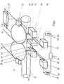
- two loops of carrier-tractor cables 10, 12 of a gondola extend in a closed circuit between two stations of which only the driving station 14 is shown, passing through the stations on pulleys 16, 18 at the ends with vertical axis 20, 22.
- the end pulleys 16, 18 of the station 14 are drive pulleys driving the cables 10, 12 continuously at the same speed.
- Each vehicle 24 is coupled by clamps 25 to the two cables 10, 12 in line, several vehicles 24 being able to follow one another or be staggered along the cables 10, 12.
- the vehicles 24 are uncoupled from the cables 10, 12 and supported by transfer rails passing in front of landing and boarding docks (not shown).
- the passengers get on and off the vehicles 24 at a standstill or traveling at low speed and at the exit from the station the vehicles 24 are accelerated wherever appropriate before being re-coupled to the cables 10, 12 on the opposite lane.
- This operation of cable cars is well known to specialists.
- the cables 10, 12 tractor-carriers are parallel and at the same level in line, their constant spacing being close to 75 cm.
- the axes 20, 22 of the driving pulleys 16,18 are the low speed shafts of reducers 26,28 whose high speed shafts 30, 32 are aligned and mechanically connected by a clutch 34.
- the shaft 30 is connected by a belt transmission 36 to a motor 38 while the shaft 32 is connected by a belt transmission 40 to an electric motor 42.
- the two kinematic chains are identical the whole being perfectly symmetrical.
- the two motors 38, 42 are supplied by the same current source 44 via control blocks 46, 48 described in detail below.
- a mechanical braking system diagrammatically represented by a braking caliper 50 enclosing the pulley 16 and a braking caliper 52 enclosing the pulley 18 is controlled by a control block 54.
- the brakes can of course be of a different type and cooperate with other parts of the drive.
- the block 54 also controls the clutch 34, so as to rigidly couple the high speed shafts 30, 32 as soon as the pulleys 16,18 are braked.
- the clutch 34 can be of the electric type or any other suitable type.
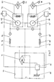
- FIG. 2 represents the electrical diagram for supplying the motors 38, 42
- these DC motors are independently energized, the inductor 56, 58 being supplied by a current source continuous, represented by a thyristor bridge 60, 62 controlled by an adjustment potentiometer 64, 66.
- the armatures 68, 70 are connected to a thyristor bridge 72 of the current source 44 by armature circuits 74, 76 in which resistors 78, 80 are inserted in series.
- the ignition of the thyristors is controlled by a control unit 82 receiving the real speed signals from the motors 38, 42 by dynamotachymetric 84, 86 a value of setpoint being provided by a potentiometer 88 for displaying the desired speed.
- Block 82 constantly compares the highest actual speed signal with the set speed and controls the conduction angle of thyristors 72 to vary the armature voltage and thereby the speed of motors 38, 42.
- Cruise control systems are well known to specialists and need not be described in more detail.
- Measuring devices in particular voltmeters V1, V2, connected to the terminals of the armatures 68, 70, measure the armature voltage and ammeters 1 1 , 1 2 , connected in the armature circuits, indicate the armature currents .
- the inductor current can also be measured and the measurement signals can be processed in signaling and control blocks (not shown).
- the drive device according to the invention operates as follows:
- the clutch 34 is disengaged and the brakes 50, 52 released.
- the motor 38 drives the pulley 16 and the motor 40 the pulley 18.
- the vehicles 24 coupled to the drive cables 10,12 constitute a connection between these cables 10, 12. If the traction force of the vehicles 24 is distributed between the cables 10, 12 the motors 38, 42 supply the pulleys 16, 18 with the same power, the currents 1 1 , 1 2 in their armature circuits being equal. Being supplied by the same current source 44 through identical resistors 78.80 their armature voltage V 1, V 2 are equal and therefore their speed of rotation.
- the cables 10, 12 move in perfect synchronism. Their speed can be adjusted by potentiometer 88 which controls the thyristor 72 ignition control block 82.
- the cable 10 in advance will ensure a greater share of the tensile force and the armature current I 1 , increases accordingly.
- the voltage drop across the resistor 78 which is equal at R 1 l 1 ' R 1 being the value of the resistance, increases and causes a drop in the armature voltage V i .
- the speed of the motor38 decreases until the balance of the powers supplied to the cables 10, 12 is restored.
- This self-regulation carried out by the resistors 78, 80 is simple and reliable and it is independent of the load of the installation or of the speed Operating. The correct operation can be checked using instruments J 1 , 1 2 , V 1 0 V 2 and the like.
- the motors 38, 42 and the resistors 78, 80 are identical, but small dispersions are inevitable. The latter can easily be compensated for by an initial calibration by means of potentiometers 64, 66 for adjusting the current of the inductors 56, 58.
- the braking order issued by the block 54 is transmitted to the clutch 34 which couples the shafts 30, 32. From this moment the pulleys 16, 18 rotate in synchronism and drive the cables 10, 12 at the same speed. Compensation for a delay of one of the cables is no longer ensured, but the deviations remain small during the braking period and are admissible.
- the friction resistances of the cables 10, 12 due in particular to frost and ice can be very different.
- the clutch 34 is engaged for synchronous movement of the cables 10, 12. After declutching the installation is ready for launching the vehicles in line.
- the clutch 34 can also be controlled by any safety device detecting a significant imbalance between the two loops 10, 12, this control generally being accompanied by emergency braking.
Landscapes
- Engineering & Computer Science (AREA)
- Power Engineering (AREA)
- Transportation (AREA)
- Mechanical Engineering (AREA)
- Electric Propulsion And Braking For Vehicles (AREA)
- Control Of Multiple Motors (AREA)
- Insulated Conductors (AREA)
- Vehicle Body Suspensions (AREA)
- Lift-Guide Devices, And Elevator Ropes And Cables (AREA)
- Electric Cable Installation (AREA)
- Ropes Or Cables (AREA)
- Refuge Islands, Traffic Blockers, Or Guard Fence (AREA)
- Braking Arrangements (AREA)
- Electrical Discharge Machining, Electrochemical Machining, And Combined Machining (AREA)
Priority Applications (1)
| Application Number | Priority Date | Filing Date | Title |
|---|---|---|---|
| AT84401920T ATE33595T1 (de) | 1983-10-03 | 1984-09-26 | Kabelantrieb einer seilbahn. |
Applications Claiming Priority (2)
| Application Number | Priority Date | Filing Date | Title |
|---|---|---|---|
| FR8315838 | 1983-10-03 | ||
| FR8315838A FR2552726B1 (fr) | 1983-10-03 | 1983-10-03 | Dispositif d'entrainement des cables d'une installation de transport a cables aeriens |
Related Child Applications (1)
| Application Number | Title | Priority Date | Filing Date |
|---|---|---|---|
| EP86116258.4 Division-Into | 1986-11-24 |
Publications (3)
| Publication Number | Publication Date |
|---|---|
| EP0140756A1 EP0140756A1 (fr) | 1985-05-08 |
| EP0140756B1 EP0140756B1 (fr) | 1988-04-20 |
| EP0140756B2 true EP0140756B2 (fr) | 1991-06-12 |
Family
ID=9292832
Family Applications (2)
| Application Number | Title | Priority Date | Filing Date |
|---|---|---|---|
| EP86116258A Expired - Lifetime EP0226838B1 (fr) | 1983-10-03 | 1984-09-26 | Dispositif d'entraînement des câbles d'une installation de transport à cables aériens |
| EP84401920A Expired - Lifetime EP0140756B2 (fr) | 1983-10-03 | 1984-09-26 | Dispositif d'entraînement des câbles d'une installation de transport à câbles aériens |
Family Applications Before (1)
| Application Number | Title | Priority Date | Filing Date |
|---|---|---|---|
| EP86116258A Expired - Lifetime EP0226838B1 (fr) | 1983-10-03 | 1984-09-26 | Dispositif d'entraînement des câbles d'une installation de transport à cables aériens |
Country Status (6)
| Country | Link |
|---|---|
| US (1) | US4619206A (en:Method) |
| EP (2) | EP0226838B1 (en:Method) |
| JP (1) | JPS60157955A (en:Method) |
| AT (2) | ATE49544T1 (en:Method) |
| DE (2) | DE3481045D1 (en:Method) |
| FR (1) | FR2552726B1 (en:Method) |
Families Citing this family (6)
| Publication number | Priority date | Publication date | Assignee | Title |
|---|---|---|---|---|
| FR2615812B1 (fr) * | 1987-05-27 | 1994-03-25 | Pomagalski Sa | Dispositif d'entrainement de plusieurs cables d'une installation de transport fonctionnant en synchronisme, et procede de regulation automatique de l'entrainement en synchrone de ces cables |
| DE9106965U1 (de) * | 1991-06-06 | 1991-08-08 | Siemens AG, 80333 München | Einzelfelderregung für Mehrmotorenantriebe |
| CA2143503A1 (en) * | 1994-03-11 | 1995-09-12 | Ernst Egli | Bypass for the cars of a circuit cable railway system |
| CA2143504A1 (en) * | 1994-03-11 | 1995-09-12 | Ernst Egli | Rope guide system for an aerial ropeway, particularly a circuital aerial ropeway |
| FR2774053B1 (fr) | 1998-01-29 | 2003-05-23 | Denis Creissels | Mecanisme d'entrainemement d'une installation de transport a cables ayant une poulie motrice a double adherence |
| FR3019126B1 (fr) * | 2014-03-28 | 2017-12-15 | Pomagalski Sa | Systeme de transport par cable |
Family Cites Families (20)
| Publication number | Priority date | Publication date | Assignee | Title |
|---|---|---|---|---|
| DE441183C (de) * | 1926-02-01 | 1927-02-25 | Foerderanlagen Ernst Heckel M | Treibscheibenantrieb |
| US1745094A (en) * | 1926-02-20 | 1930-01-28 | Frederic W Hild | Regulating device |
| DE517409C (de) * | 1930-01-19 | 1931-02-04 | Pohlig A G J | Elektrischer Antrieb fuer Seilbahnen, insbesondere fuer Personen-Seilschwebebahnen mit festem Tragseil und mehreren Zugseilen |
| DE630022C (de) * | 1935-04-14 | 1936-05-23 | Bleichert Transportanlagen G M | Drahtseilbahn mit zwei Teilstrecken und Antrieb in der Zwischenstation |
| US2168777A (en) * | 1937-05-05 | 1939-08-08 | Jones & Laughlin Steel Corp | Tension control for strip mills |
| US2586412A (en) * | 1948-06-19 | 1952-02-19 | Westinghouse Electric Corp | Control system for dynamoelectric machines |
| US2771790A (en) * | 1954-07-12 | 1956-11-27 | Niagara Machine & Tool Works | Double drive power punch press |
| FR1249949A (fr) * | 1959-11-24 | 1961-01-06 | Const Aero Navales | Installation de téléphérage |
| GB1078195A (en) * | 1964-01-15 | 1967-08-02 | Kh Elektromekhanic Hesky Zd | Arrangements for equalizing loads on d.c. machines operating in parallel |
| CA905527A (en) * | 1970-11-12 | 1972-07-18 | Canadian Westinghouse Company Limited | Twin double drum hoisting system |
| US3688167A (en) * | 1970-11-19 | 1972-08-29 | Westinghouse Electric Corp | Slave current control system for a plurality of electric motors coupled to a common load |
| US3788606A (en) * | 1972-05-09 | 1974-01-29 | Schat Davits Ltd | Winch mechanism for lowering a lifeboat, launch or the like, suspended from two falls, into the water and hoisting it out of the water |
| GB1370181A (en) * | 1973-03-05 | 1974-10-16 | British Ropeway Eng Co Ltd | Aerial ropeways rope conveyors and other rope haulage systems |
| US3991349A (en) * | 1975-01-03 | 1976-11-09 | Westinghouse Electric Corporation | Droop adjustable control apparatus for direct current motor drives |
| DE2518753B2 (de) * | 1975-04-26 | 1981-03-12 | Eisenhütte Prinz Rudolph, Zweigniederlassung der Salzgitter Maschinen und Anlagen AG, 4408 Dülmen | Zweiträumige Schachtfördermaschine, insbesondere Ab- und Weiterteufhaspel |
| US4100822A (en) * | 1976-04-19 | 1978-07-18 | Allan Rosman | Drive system for a moving mechanism |
| FR2448464A1 (en) * | 1979-02-07 | 1980-09-05 | Creissels Denis | Overhead cable transporter system - has two endless driven cables supporting trolley with duplicate system by side for sharing heavy loads |
| FR2450187A1 (fr) * | 1979-02-27 | 1980-09-26 | Ogoque Cie Miniere Comilog | Dispositif de stabilisation de vitesse pour installation de transport a cable aerien |
| CA1153449A (en) * | 1979-07-16 | 1983-09-06 | Gordon M. Sommer | Drive system |
| FR2525981B1 (fr) * | 1982-04-28 | 1985-06-07 | Creissels Denis | Telecabine a deux cables porteurs tracteurs |
-
1983
- 1983-10-03 FR FR8315838A patent/FR2552726B1/fr not_active Expired
-
1984
- 1984-09-26 AT AT86116258T patent/ATE49544T1/de not_active IP Right Cessation
- 1984-09-26 US US06/654,657 patent/US4619206A/en not_active Expired - Lifetime
- 1984-09-26 EP EP86116258A patent/EP0226838B1/fr not_active Expired - Lifetime
- 1984-09-26 DE DE8686116258T patent/DE3481045D1/de not_active Expired - Lifetime
- 1984-09-26 AT AT84401920T patent/ATE33595T1/de not_active IP Right Cessation
- 1984-09-26 DE DE8484401920T patent/DE3470500D1/de not_active Expired
- 1984-09-26 EP EP84401920A patent/EP0140756B2/fr not_active Expired - Lifetime
- 1984-10-02 JP JP59205716A patent/JPS60157955A/ja active Granted
Also Published As
| Publication number | Publication date |
|---|---|
| US4619206A (en) | 1986-10-28 |
| JPS60157955A (ja) | 1985-08-19 |
| ATE49544T1 (de) | 1990-02-15 |
| EP0226838A2 (fr) | 1987-07-01 |
| DE3481045D1 (de) | 1990-02-22 |
| EP0226838A3 (en) | 1987-08-26 |
| EP0140756B1 (fr) | 1988-04-20 |
| ATE33595T1 (de) | 1988-05-15 |
| FR2552726B1 (fr) | 1985-11-29 |
| EP0226838B1 (fr) | 1990-01-17 |
| EP0140756A1 (fr) | 1985-05-08 |
| JPH0441112B2 (en:Method) | 1992-07-07 |
| DE3470500D1 (en) | 1988-05-26 |
| FR2552726A1 (fr) | 1985-04-05 |
Similar Documents
| Publication | Publication Date | Title |
|---|---|---|
| EP0491632B1 (fr) | Télécabine ou télésiège débrayable à deux boucles de câble | |
| FR2730968A1 (fr) | Mecanisme de frein de voie pour wagons | |
| EP0093680B1 (fr) | Télécabine à deux câbles porteurs-tracteurs | |
| CA2378636C (fr) | Procede et dispositif de pilotage de l'alimentation en energie electrique d'un vehicule a traction electrique destine a fonctionner en mode d'alimentation externe ou en mode d'alimentation autonome | |
| EP0140756B2 (fr) | Dispositif d'entraînement des câbles d'une installation de transport à câbles aériens | |
| FR2600302A1 (fr) | Dispositif d'entrainement avec un systeme variable de limitation de couple, notamment pour la commande des volets d'atterrissage d'aeronefs | |
| FR2571675A1 (fr) | Installation de transport a cable aerien a plusieurs sections | |
| EP0210085A1 (fr) | Installation de transport à câble aérien à arrêt du câble pour le débrayage des cabines en station | |
| EP0181243B1 (fr) | Telecabine ou telesiege debrayable a transmission electrique | |
| EP0461954B1 (fr) | Dispositif cadenceur d'un téléporteur débrayable | |
| US3071083A (en) | Monocable aerial ropeway | |
| FR3025163A1 (fr) | Installation et procede de transport par cable aerien | |
| EP0922620B1 (fr) | Procédé de stockage et déstockage de cabines dans les gares d'une installation de transport à cable aérien | |
| EP0015211B1 (fr) | Dispositif de stabilisation de vitesse pour installation de transport à câble aérien | |
| FR2605574A1 (fr) | Installation de transport ayant un cable aerien a defilement continu et des systemes lanceur et ralentisseur | |
| EP2014533A1 (fr) | Installation de transport par cable aérien comportant un circuit de transfert des véhicules muni d'un moteur-couple | |
| EP0293296B1 (fr) | Dispositif d'entrainement de plusieurs cables d'une installation de transport fonctionnant en synchronisme, et procédé de régulation automatique de l'entrainement en synchronisme de ces cables | |
| FR2473441A1 (fr) | Systeme de convoyeur perfectionne, permettant une modification simple et efficace des caracteristiques de transport, et commande simple de cette modification | |
| FR2933359A1 (fr) | Installation de transport a deux boucles de cable raccordees dans un local intermediaire | |
| EP2691278B1 (fr) | Téléporteur aérien à va-et-vient et à tronçons multiples | |
| EP3805036A1 (fr) | Dispositif de freinage à courants de foucault | |
| SU1093634A1 (ru) | Магнитно-фрикционный электропривод ленточного конвейера | |
| FR2639304A1 (fr) | Telepherique debrayable a dispositif de deceleration ou d'acceleration des vehicules | |
| FR2521949A1 (fr) | Treuil de remorquage double | |
| PL190082B1 (pl) | Wózek podwieszony napędowy zasilany bateryjnie |
Legal Events
| Date | Code | Title | Description |
|---|---|---|---|
| PUAI | Public reference made under article 153(3) epc to a published international application that has entered the european phase |
Free format text: ORIGINAL CODE: 0009012 |
|
| AK | Designated contracting states |
Designated state(s): AT CH DE IT LI SE |
|
| RAP1 | Party data changed (applicant data changed or rights of an application transferred) |
Owner name: CREISSELS, DENIS |
|
| 17P | Request for examination filed |
Effective date: 19850827 |
|
| 17Q | First examination report despatched |
Effective date: 19860731 |
|
| ITF | It: translation for a ep patent filed | ||
| GRAA | (expected) grant |
Free format text: ORIGINAL CODE: 0009210 |
|
| AK | Designated contracting states |
Kind code of ref document: B1 Designated state(s): AT CH DE IT LI SE |
|
| REF | Corresponds to: |
Ref document number: 33595 Country of ref document: AT Date of ref document: 19880515 Kind code of ref document: T |
|
| REF | Corresponds to: |
Ref document number: 3470500 Country of ref document: DE Date of ref document: 19880526 |
|
| PLBI | Opposition filed |
Free format text: ORIGINAL CODE: 0009260 |
|
| 26 | Opposition filed |
Opponent name: POMAGALSKI S.A. Effective date: 19890113 |
|
| PUAH | Patent maintained in amended form |
Free format text: ORIGINAL CODE: 0009272 |
|
| STAA | Information on the status of an ep patent application or granted ep patent |
Free format text: STATUS: PATENT MAINTAINED AS AMENDED |
|
| 27A | Patent maintained in amended form |
Effective date: 19910612 |
|
| AK | Designated contracting states |
Kind code of ref document: B2 Designated state(s): AT CH DE IT LI SE |
|
| ITF | It: translation for a ep patent filed | ||
| REG | Reference to a national code |
Ref country code: CH Ref legal event code: AEN |
|
| ITTA | It: last paid annual fee | ||
| EAL | Se: european patent in force in sweden |
Ref document number: 84401920.8 |
|
| PGFP | Annual fee paid to national office [announced via postgrant information from national office to epo] |
Ref country code: SE Payment date: 19970918 Year of fee payment: 14 |
|
| PGFP | Annual fee paid to national office [announced via postgrant information from national office to epo] |
Ref country code: DE Payment date: 19971010 Year of fee payment: 14 |
|
| PGFP | Annual fee paid to national office [announced via postgrant information from national office to epo] |
Ref country code: AT Payment date: 19980914 Year of fee payment: 15 |
|
| PG25 | Lapsed in a contracting state [announced via postgrant information from national office to epo] |
Ref country code: SE Free format text: LAPSE BECAUSE OF NON-PAYMENT OF DUE FEES Effective date: 19980927 |
|
| PGFP | Annual fee paid to national office [announced via postgrant information from national office to epo] |
Ref country code: CH Payment date: 19981009 Year of fee payment: 15 |
|
| EUG | Se: european patent has lapsed |
Ref document number: 84401920.8 |
|
| PG25 | Lapsed in a contracting state [announced via postgrant information from national office to epo] |
Ref country code: DE Free format text: LAPSE BECAUSE OF NON-PAYMENT OF DUE FEES Effective date: 19990701 |
|
| PG25 | Lapsed in a contracting state [announced via postgrant information from national office to epo] |
Ref country code: AT Free format text: LAPSE BECAUSE OF NON-PAYMENT OF DUE FEES Effective date: 19990926 |
|
| PG25 | Lapsed in a contracting state [announced via postgrant information from national office to epo] |
Ref country code: LI Free format text: LAPSE BECAUSE OF NON-PAYMENT OF DUE FEES Effective date: 19990930 Ref country code: CH Free format text: LAPSE BECAUSE OF NON-PAYMENT OF DUE FEES Effective date: 19990930 |
|
| REG | Reference to a national code |
Ref country code: CH Ref legal event code: PL |