EP0140364B1 - Schraubkupplung für Rohrstutzen mit Aussengewinde - Google Patents
Schraubkupplung für Rohrstutzen mit Aussengewinde Download PDFInfo
- Publication number
- EP0140364B1 EP0140364B1 EP84113041A EP84113041A EP0140364B1 EP 0140364 B1 EP0140364 B1 EP 0140364B1 EP 84113041 A EP84113041 A EP 84113041A EP 84113041 A EP84113041 A EP 84113041A EP 0140364 B1 EP0140364 B1 EP 0140364B1
- Authority
- EP
- European Patent Office
- Prior art keywords
- screw
- screw caps
- sleeve
- bottoms
- caps
- Prior art date
- Legal status (The legal status is an assumption and is not a legal conclusion. Google has not performed a legal analysis and makes no representation as to the accuracy of the status listed.)
- Expired
Links
Images
Classifications
-
- F—MECHANICAL ENGINEERING; LIGHTING; HEATING; WEAPONS; BLASTING
- F16—ENGINEERING ELEMENTS AND UNITS; GENERAL MEASURES FOR PRODUCING AND MAINTAINING EFFECTIVE FUNCTIONING OF MACHINES OR INSTALLATIONS; THERMAL INSULATION IN GENERAL
- F16L—PIPES; JOINTS OR FITTINGS FOR PIPES; SUPPORTS FOR PIPES, CABLES OR PROTECTIVE TUBING; MEANS FOR THERMAL INSULATION IN GENERAL
- F16L15/00—Screw-threaded joints; Forms of screw-threads for such joints
- F16L15/006—Screw-threaded joints; Forms of screw-threads for such joints with straight threads
- F16L15/008—Screw-threaded joints; Forms of screw-threads for such joints with straight threads with sealing rings
Definitions
- the present invention relates to an improved screw coupling for pipes and pipe sockets.
- Such screw couplings consist of two screw caps with an internal thread and a perforated bottom, which are arranged facing each other with a bottom, and a sleeve which extends through these holes in the screw caps and is flanged at its two open ends in such a way that it engages around the inside of the bottom of the screw caps , whereby the two screw caps are rotatably connected to one another about their longitudinal axis.
- This sleeve preferably has a circumferential bead on the middle of its outer wall, which serves as a spacer between the two screw caps.
- the two screw caps can be rotated independently about their common axis, and as a result the two pipe sockets can be easily detached from one another.
- the aim of the present invention is therefore a pipe coupling of the type described, which has the required tightness, without the pipe ends having to be subjected to a complex grinding process.
- This goal is achieved according to the invention in that a ring made of elastic material is placed between the flanging of the sleeve and the inside of the bottom of the screw cap.
- the screw caps are preferably made of hard plastic and the sleeve is preferably made of polytetrafluoroethylene.
- the ring which is the subject of the present invention, can consist of any suitable material and is preferably made of an elastomer; a suitable material is, for example, silicone rubber.
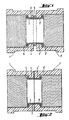
- the two screw caps 1, 1 ' are connected to one another by the sleeve 2, which engages around the inside of the bases 4, 4' of the screw caps (flange 6, 6 '); the bead 5 of the sleeve 2 acts as a spacer (Fig. 1).
- Fig. 2 differs from Fig. 1 in that the bead 5 is not present.
- the screw coupling described is used in a particularly advantageous manner on glass tubes and apparatus in the chemical laboratory area.
Landscapes
- Engineering & Computer Science (AREA)
- General Engineering & Computer Science (AREA)
- Mechanical Engineering (AREA)
- Mutual Connection Of Rods And Tubes (AREA)
- Joints With Pressure Members (AREA)
- Non-Disconnectible Joints And Screw-Threaded Joints (AREA)
Description
- Die vorliegende Erfindung betrifft eine verbesserte Schraubkupplung für Rohre und Rohrstutzen.
- Derartige Schraubkupplungen sind bekannt. Sie bestehen aus zwei Schraubkappen mit Innengewinde und durchbohrtem Boden, die mit diesen Böden zueinandergekehrt angeordnet sind, und aus einer Hülse, welche durch diese Bohrungen der Schraubkappen hindurchreicht und an ihren beiden offenen Enden derart umbördelt ist, dass sie die Innenseiten der Böden der Schraubkappen umgreift, wodurch die beiden Schraubkappen um ihre Längsachse drehbar miteinander verbunden sind. Vorzugsweise weist diese Hülse an der Mitte ihrer Aussenwand eine umlaufende Wulst auf, die als Abstandhalter zwischen den beiden Schraubkappen dient.
- Dank ihrer Anordnung und Bauweise sind die beiden Schraubkappen um ihre gemeinsame Achse unabhängig drehbar, und dadurch sind die beiden Rohrstutzen leicht voneinander lösbar.
- Ein Nachteil dieser bekannten Schraubkupplung besteht jedoch darin, dass, da die Rohrenden im allgemeinen nicht plan und nicht exakt rechtwinklig zur Rohrlängsachse sind, derartige Verbindungen nicht dicht sind. Um ausreichende Dichtheit zu erzielen, müssten beide Rohrenden plan und genau rechtwinklig zur Rohrlängsachse geschliffen werden. Das ist ein wirtschaftlich kaum vertretbarer Aufwand.
- Ziel der vorliegenden Erfindung ist daher eine Rohrkupplung der geschilderten Art, die die erforderliche Dichtigkeit aufweist, ohne dass die Rohrenden einem aufwendigen Schleifprozess unterzogen werden müssen.
- Dieses Ziel wird gemäss der Erfindung dadurch erreicht, dass jeweils zwischen die Umbördelung der Hülse und die Innenseite des Bodens der Schraubkappe ein Ring aus elastischem Werkstoff gelegt ist.
- Die Schraubkappen bestehen vorzugsweise aus Hartkunststoff, und die Hülse besteht vorzugsweise aus Polytetrafluoräthylen.
- Der Ring, der Gegenstand der vorliegenden Erfindung ist, kann aus beliebigem geeignetem Material bestehen und ist vorzugsweise aus einem Elastomeren gefertigt; ein geeignetes Material ist beispielsweise Silikongummi.
- Die Erfindung wird durch die Zeichnung näher erläutert. Es zeigen:
- Fig. 1 einen Schnitt einer ersten Ausführungsform der Schraubkupplung gemäss der Erfindung.
- Fig. 2 einen Schnitt einer zweiten Ausführungsform der Schraubkupplung gemäss der Erfindung.
- Die beiden Schraubkappen 1,1' sind durch die Hülse 2 miteinander verbunden, welche die Böden 4, 4' der Schraubkappen innen umgreift (Umbördelung 6,6'); der Wulst 5 der Hülse 2 wirkt als Abstandhalter (Fig. 1).
- Zwischen die Umbördelung 6,6' und die Innenseite des Bodens 4, 4' ist jeweils ein Ring 3, 3' aus Silikongummi gelegt. Fig. 2 unterscheidet sich von Fig. 1 dadurch, dass der Wulst 5 nicht vorhanden ist.
- Die geschilderte Schraubkupplung findet in besonders vorteilhafter Weise Verwendung an Glasrohren und -apparaturen im Chemielaborbereich.
Claims (2)
Priority Applications (1)
| Application Number | Priority Date | Filing Date | Title |
|---|---|---|---|
| AT84113041T ATE32939T1 (de) | 1983-11-02 | 1984-10-30 | Schraubkupplung fuer rohrstutzen mit aussengewinde. |
Applications Claiming Priority (2)
| Application Number | Priority Date | Filing Date | Title |
|---|---|---|---|
| DE19838331373U DE8331373U1 (de) | 1983-11-02 | 1983-11-02 | Schraubkupplung fuer rohrstutzen mit aussengewinde |
| DE8331373U | 1983-11-02 |
Publications (3)
| Publication Number | Publication Date |
|---|---|
| EP0140364A2 EP0140364A2 (de) | 1985-05-08 |
| EP0140364A3 EP0140364A3 (en) | 1985-08-21 |
| EP0140364B1 true EP0140364B1 (de) | 1988-03-09 |
Family
ID=6758492
Family Applications (1)
| Application Number | Title | Priority Date | Filing Date |
|---|---|---|---|
| EP84113041A Expired EP0140364B1 (de) | 1983-11-02 | 1984-10-30 | Schraubkupplung für Rohrstutzen mit Aussengewinde |
Country Status (3)
| Country | Link |
|---|---|
| EP (1) | EP0140364B1 (de) |
| AT (1) | ATE32939T1 (de) |
| DE (1) | DE8331373U1 (de) |
Families Citing this family (2)
| Publication number | Priority date | Publication date | Assignee | Title |
|---|---|---|---|---|
| DE19836273C1 (de) * | 1998-08-11 | 2000-04-20 | Meibes Holding Gmbh Geb | Rohrverbindung mit Gewinde |
| DE10103906A1 (de) * | 2001-01-30 | 2002-10-31 | Joerg Redeker | Schraubkupplung für gewindetragende Laborglasgerätekomponenten |
Family Cites Families (6)
| Publication number | Priority date | Publication date | Assignee | Title |
|---|---|---|---|---|
| DE7115019U (de) * | 1971-07-22 | Fischer G Ag | Verschraubung mit zwei Überwurfmuttern, insbesondere für rohrförmige T- und/oder Winkelstücke | |
| US1431513A (en) * | 1921-06-20 | 1922-10-10 | Henry E Cox | Coupling for rotary pipes |
| US2457633A (en) * | 1946-02-21 | 1948-12-28 | Gustave A Borg | Sealing device |
| US3130988A (en) * | 1959-10-14 | 1964-04-28 | Bar Way Mfg Company | Hose coupling |
| US3338597A (en) * | 1966-10-13 | 1967-08-29 | Nat Distillers Chem Corp | Supply tube adapters narrow supply tube-narrow inlet |
| FR2450401A3 (fr) * | 1979-02-27 | 1980-09-26 | Guibert Jean Charles | Joint realise par trempage ou projection |
-
1983
- 1983-11-02 DE DE19838331373U patent/DE8331373U1/de not_active Expired
-
1984
- 1984-10-30 AT AT84113041T patent/ATE32939T1/de not_active IP Right Cessation
- 1984-10-30 EP EP84113041A patent/EP0140364B1/de not_active Expired
Also Published As
| Publication number | Publication date |
|---|---|
| ATE32939T1 (de) | 1988-03-15 |
| EP0140364A2 (de) | 1985-05-08 |
| EP0140364A3 (en) | 1985-08-21 |
| DE8331373U1 (de) | 1984-02-02 |
Similar Documents
| Publication | Publication Date | Title |
|---|---|---|
| DE3382690T2 (de) | Rohrverbindung. | |
| DE2230191C3 (de) | Rohranschlußverbindung | |
| DE3519662C2 (de) | ||
| DE2918492C2 (de) | ||
| DE1963548A1 (de) | Vorrichtung zur Verbindung rohrfoermiger Elemente | |
| WO2012010168A2 (de) | Vorrichtung zur fixierung eines kabels an einen kabelabgangsstutzen | |
| DE2816645A1 (de) | Anordnung zur drehbaren verbindung eines saugschlauches mit einem kupplungsstueck bei einem staubsauger | |
| DE3882336T2 (de) | Servo-Bremskraftverstärker. | |
| DE2819623C3 (de) | Brausevorrichtung | |
| DE2402892C2 (de) | Dichtungssystem für die stirnseitige Verbindung eines Rohres mit einem schraubenförmig gewellten Rohr | |
| EP0061569A1 (de) | Muffe | |
| DE2230909C2 (de) | Mehrwegeventil | |
| DE69615961T2 (de) | Hermetisch abgedichtete Struktur zum Verbinden von zwei Wellenleitern | |
| EP0140364A2 (de) | Schraubkupplung für Rohrstutzen mit Aussengewinde | |
| DE3527685C2 (de) | ||
| EP0482332A1 (de) | Vorrichtung zur Injektion von Druckluft in eine Flüssigkeit | |
| DE2612240A1 (de) | Rohrverbindungseinrichtung | |
| DE102004034023A1 (de) | Teleskoprohr | |
| DE3500767C2 (de) | ||
| EP0099443A2 (de) | Hochdruckautoklav | |
| CH657436A5 (de) | Verschraubungssystem. | |
| AT200935B (de) | Kugelgelenk, insbesondere für Radaufhängungen von Kraftfahrzeugen | |
| DE69000599T2 (de) | Fluessigkeitsspeicher. | |
| DE2557996A1 (de) | Loesbare anschlussverbindung fuer hydraulik- und/oder pneumatik-leitungen | |
| DE619161C (de) | Rohrverbindung mit einer die Rohre umfassenden Muffe und Klemmhuelsen |
Legal Events
| Date | Code | Title | Description |
|---|---|---|---|
| PUAI | Public reference made under article 153(3) epc to a published international application that has entered the european phase |
Free format text: ORIGINAL CODE: 0009012 |
|
| AK | Designated contracting states |
Designated state(s): AT CH FR GB IT LI |
|
| RTI1 | Title (correction) | ||
| PUAL | Search report despatched |
Free format text: ORIGINAL CODE: 0009013 |
|
| AK | Designated contracting states |
Designated state(s): AT CH FR GB IT LI |
|
| 17P | Request for examination filed |
Effective date: 19850920 |
|
| 17Q | First examination report despatched |
Effective date: 19861006 |
|
| GRAA | (expected) grant |
Free format text: ORIGINAL CODE: 0009210 |
|
| AK | Designated contracting states |
Kind code of ref document: B1 Designated state(s): AT CH FR GB IT LI |
|
| REF | Corresponds to: |
Ref document number: 32939 Country of ref document: AT Date of ref document: 19880315 Kind code of ref document: T |
|
| RAP2 | Party data changed (patent owner data changed or rights of a patent transferred) |
Owner name: CARL-ZEISS-STIFTUNG TRADING AS SCHOTT GLASWERKE Owner name: SCHOTT GLASWERKE |
|
| ITF | It: translation for a ep patent filed | ||
| ET | Fr: translation filed | ||
| GBT | Gb: translation of ep patent filed (gb section 77(6)(a)/1977) | ||
| PLBE | No opposition filed within time limit |
Free format text: ORIGINAL CODE: 0009261 |
|
| STAA | Information on the status of an ep patent application or granted ep patent |
Free format text: STATUS: NO OPPOSITION FILED WITHIN TIME LIMIT |
|
| 26N | No opposition filed | ||
| ITTA | It: last paid annual fee | ||
| PGFP | Annual fee paid to national office [announced via postgrant information from national office to epo] |
Ref country code: CH Payment date: 19940914 Year of fee payment: 11 |
|
| PGFP | Annual fee paid to national office [announced via postgrant information from national office to epo] |
Ref country code: GB Payment date: 19940915 Year of fee payment: 11 |
|
| PGFP | Annual fee paid to national office [announced via postgrant information from national office to epo] |
Ref country code: FR Payment date: 19940919 Year of fee payment: 11 |
|
| PGFP | Annual fee paid to national office [announced via postgrant information from national office to epo] |
Ref country code: AT Payment date: 19940921 Year of fee payment: 11 |
|
| PG25 | Lapsed in a contracting state [announced via postgrant information from national office to epo] |
Ref country code: GB Effective date: 19951030 Ref country code: AT Effective date: 19951030 |
|
| PG25 | Lapsed in a contracting state [announced via postgrant information from national office to epo] |
Ref country code: LI Effective date: 19951031 Ref country code: CH Effective date: 19951031 |
|
| REG | Reference to a national code |
Ref country code: CH Ref legal event code: PL |
|
| GBPC | Gb: european patent ceased through non-payment of renewal fee |
Effective date: 19951030 |
|
| PG25 | Lapsed in a contracting state [announced via postgrant information from national office to epo] |
Ref country code: FR Effective date: 19960628 |
|
| REG | Reference to a national code |
Ref country code: FR Ref legal event code: ST |