EP0138581A2 - Druckmechanismus - Google Patents
Druckmechanismus Download PDFInfo
- Publication number
- EP0138581A2 EP0138581A2 EP84306946A EP84306946A EP0138581A2 EP 0138581 A2 EP0138581 A2 EP 0138581A2 EP 84306946 A EP84306946 A EP 84306946A EP 84306946 A EP84306946 A EP 84306946A EP 0138581 A2 EP0138581 A2 EP 0138581A2
- Authority
- EP
- European Patent Office
- Prior art keywords
- printing
- printing head
- ink
- printing mechanism
- head
- Prior art date
- Legal status (The legal status is an assumption and is not a legal conclusion. Google has not performed a legal analysis and makes no representation as to the accuracy of the status listed.)
- Withdrawn
Links
Images


Classifications
-
- B—PERFORMING OPERATIONS; TRANSPORTING
- B65—CONVEYING; PACKING; STORING; HANDLING THIN OR FILAMENTARY MATERIAL
- B65B—MACHINES, APPARATUS OR DEVICES FOR, OR METHODS OF, PACKAGING ARTICLES OR MATERIALS; UNPACKING
- B65B61/00—Auxiliary devices, not otherwise provided for, for operating on sheets, blanks, webs, binding material, containers or packages
- B65B61/26—Auxiliary devices, not otherwise provided for, for operating on sheets, blanks, webs, binding material, containers or packages for marking or coding completed packages
Definitions
- This invention relates to a printing mechanism, especially but not exclusively an over-printing mechanism, for use, for example, in packaging machinery or label-production machinery.
- a known high speed over-printing mechanism (for example 300 print actions per minute) comprises a heated roller impregnated with a thermoplastics ink and a printing head (also heated) adapted for movement arcuately to wipe the type carried by the printing head across the roller to transfer the softened ink onto the type, and then axially to effect a printing action, the softened ink solidifying as it contacts the material to be printed, and the roller and printing head being controlled, due to the required high-speed action, electrically and electronically.
- a printing mechanism comprising an ink support impregnated with a thermoplastics ink and adapted to be heated to soften the ink, a movable printing head disposed adjacent the ink support and adapted to carry type onto which softened thermoplastics ink can be transferred from the ink support, and pneumatic actuating means connected to the printing head and adapted to effect a first movement of the latter across the ink support to effect an ink transfer and then a second movement to bring the printing head temporarily into contact with the material or article to be printed at a printing location.
- the printing mechanism comprise a pivotal ink support and a pivotal printing head disposed alongside the ink support, the pneumatic actuating means being connected to the printing head so as to pivot same through an arcuate path from a parked location to a printing location whereat it imparts a rectilinear movement to the printing head to effect a printing operation and back again, and connecting means between the pneumatic actuating means and the pivotal ink support to pivot the latter towards the printing head during the first arcuate movement of the latter to effect a wiping, ink transfer, contact between the ink support and the printing head.
- the pivotal cradle and the printing head are movable by two separate double-acting pneumatic cylinders, the cradle cylinder moving the cradle clear of the printing head on its atcuate movement away from the printing location and returning it to its original position for contact between the printing head and the ink roller as the printing head moves back to the printing position where, an additional movement, of the printing head cylinder moves the printing head to effect a printing operation.
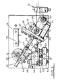
- the printing mechanism is enclosed in a casing generally indicated at 20 having a transparent and removable front wall formed with an arcuate slot 21 for a purpose to be described later and a bottom opening 22 at the printing head end of the casing 20.
- this printing mechanism will be mounted by suitable bracketting (not shown) at a suitable location in a packaging line or label production line for example. As such lines do not constitute part of the present invention they are not illustrated or described.
- the printing mechanism would usually be employed for over-printing, i.e. printing on already printed packages, packing materials or labels.
- the casing 20 comprises a mounting plate 23 on one side of which is pivoted as indicated at 24 a cradle 25 having a central spindle 26 on which is mounted, a disposable roller 27 having a body 28 of foam plastics ' or other porous material impregnated with a thermoplastics ink which is solid at ambient temperatures but which softens when heated.
- the roller 27 is removably retained on the spindle 26 by a tubular core 29.
- the cradle 25 incorporates heating elements generally indicated at 30 for heating the ink roller 27, 28. Alternatively, the latter is heated via the spindle 26 which incorporates a heating element or is itself a heating element.
- An inclined arm 31 is connected to the cradle 25 and extends upwardly therefrom and is secured to a plate 32 by screws 33, the plate 32 extending upwardly from the arm 31.
- the screws 33 permit relative adjustment between the arm 31 and the plate 32 to be effected to determine correct disposition between the ink roller 27, 28 and the printing head (to be referred to later) of the printing mechanism during an ink transfer operation.
- a stop or pin 34 is secured to the plate 36 intermediate its upper and lower ends and towards one edge thereof for a purpose to be described later.
- a lever 35 is pivoted intermediate its ends as indicated at 36 to the plate 32 and at one end the lever 35 mounts a cam follower 36A while its other end is connected by a spring 37 to the lower end of the plate 32.
- the lever 35 bears on the stop 34.
- An adjustable stop 25A contacts the cradle 25 to determine the position of the ink transfer roller 27, 28 relative to the printing head generally indicated at 38 and disposed alongside the cradle 25 when the printing head 38 is in a parked position as shown in Figs. 1 and 4.
- the printing head 38 comprises a type carrier 39 which has a handle 40 movable along the arcuate slot 21. which consequently acts as a guide.
- the type carrier 39 is removably and slidably supported by a heater block 41 which is secured by a screw 42 on an arm 43 having a pivot spindle 44.
- the arm 43 carries a spring-loaded adjustable screw or stop 45 adapted to contact a buffer 46 which determines the printing position of the printing head 38.
- a print worktable 47 is provided below the opening 22 in the casing 20 to support the article to be printed.
- This table 47 is, as is well known in the art, height-adjustable and has a levelling facility.
- the rotatable pivot spindle 44 extends through a hole 48 in the plate 23 and is supported in a bush 49 at the rear of the plate 23.
- the bush 49 is slidable on two vertical rods 50 held in a bracket 51 secured to the back of the plate 23 by screws 52.
- a spring 53 is mounted between the bush 49 and the bracket 51 and serves to hold the printing head 38 clear of its printing position.
- An arm or plate 54 is secured to the printing head 38 alongside the arm 43 and is pivotally connected at 55 to one end of a link 56, the other end of which is pivotally connected at 57 to a cam 58 which is in contact with the follower 36A on the lever 35.
- the plate 32 carrying the latter is connected at its upper end by a spring 59 connected to the plate 23 at the back of the cam 58.
- the cam 58 is rotatably supported by a spindle 60 with which is fast a pinion 61 at the back of the plate 23 and with which meshes a rack 62 movably supported in a guide 63 and connected via a clevis 64 to the spindle 65 of a double-acting pneumatic cylinder 66 supported on a plate 67 by a cylinder holder 68, the plate 67 being mounted on the plate 23.
- the cylinder 66 is fitted with two flow-control or regulating valves 69 which are set to give the required cam movements.
- a shock absorber 70 has its cylinder 71 supported on the cylinder holder 68 and its spindle 72 and contact head 73 are directed towards the clevis 64 for contact therewith as the latter moves towards the shock absorber 70.
- the flow of compressed air to and from the air cylinder 66 via the ports 69 is controlled by a five port solenoid valve diagrammatically illustrated at 74, a suitable pressurised air source (not shown) being provided.
- Such signal to the solenoid valve 74 may be a specified voltage signal or a non-voltage signal determined by an option selector OS.
- the electrical control circuit (Fig. 10) for the printing mechanism is supplied from the mains EM and the supply also includes a voltage selector VS and feeds a power supply PS to the control circuit.
- the latter includes a "run" switch RS operable by the signal (or non-signal) AS from the packaging or label production machine to activate or de-activate the solenoid valve 74 and consequently the printing mechanism.
- the heater circuits for the ink roller 27, 28 and the printing head 38 are separately controlled by snap thermostats 75 and 76 respectively (see Fig. 1).
- the control circuit includes a first potentiometer PI which serves as a delay timer which delays the signal from the package or label production machine until the article to be over-printed has come to rest; and a second potentiometer P2 which serves to adjust the dwell time of the printing head, i.e. the time of contact between the printing head 38 and the article being printed.
- the solenoid valve 74 is operated by the control circuit via a solenoid valve driver SVD as is well known in the art.
- the electrical wiring of the printing mechanism has been omitted for convenience and so as not to over-complicate the drawing but the wiring would normally be connected to the control circuit via the terminal block 77.
- the solenoid valve 74 operates to cause the rack 62 to rotate the cam 58 clockwise (see Fig. 5) to move the printing head 38 towards the printing position shown in Fig. 6, the connection point 57 being moved downwardly by the cam 58 to effect such bodily movement of the printing head.
- the nose of the cam 58 acts on the follower 36A to lock the pivotal lever 35 against the stop 34 so that the lever 35, plate 32, arm 31 and the cradle 25 become temporarily unitised so that the latter is pivoted about its axis 24 towards the downwardly moving printing head 38. The latter is thus wiped across the surface of the ink roller 27, 28 to effect an ink transfer operation from the latter to the type of the printing head 38.
- the nose of the cam 58 during this movement serves to pivot the lever 35 away from the stop 34 so that there is no movement of the cradle 25 from its parked position, the spring 37 returning the lever 35 to its normal, non-operational disposition and the cam follower 36A simply following the cam surface non-actively.
- the printing mechanism is now at rest until another "run” signal is received from the packaging machine or the label production machine.
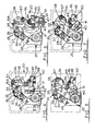
- Figs. 8 and 9 show an alternative configuration of over-printing mechanism according to the present invention.
- the printing mechanism again comprises a vertical plate 100 which would be located at a desired location on a packaging or label production line.
- the printing mechanism comprises an ink support or carrier 101 and a printing head 102.
- the ink support or carrier 101 is a disposable roller 103 of foam plastics or other porous material impregnated with a thermoplastics ink which is solid at ambient temperatures but softens when heated.
- the roller 103 is freely supported on a spindle 104 carried by a cradle 105 pivoted along an axis 106 on a bracket or arm 107 fixed to the plate 100.
- the cradle 105 has an aluminium shroud 108 adjacent the periphery of the roller 103 and has cartridge heaters (not shown) for providing the heating for melting the thermoplastics ink in the roller 103. The latter is thus peripherally heated.
- the electrical connections to the cartridge heaters are generally indicated at 109. Alternatively, or additionally, heating may be effected through the spindle 104 at the centre of the roller 103.
- the cradle 105 has an upper arm 110 to which is connected the piston rod 111 of a double-acting pneumatic ram 112 connected at its other end to the plate 100 as indicated at 113.
- a spring 114 is connected between the plate 100 and the arm 110 to assist anti-clockwise movement of the cradle 105.
- Air supply pipes to the cylinder 115 of the ram 112 are indicated at 116 and each pipe 116 is connected to a flow restrictor 117 which controls the speed of operation of the ram 112.
- the printing head 102 has a type carrier 118 which is heated electrically as can be viewed at 119 and the type is generally indicated at 120.
- the printing head 102 is rotatably supported in a bearing 121 which extends through the plate 100.
- This bearing 121 is supported for axial movement by a bracket assembly 122 slidably on two rods 123 carried by a fixed bar 124 and a fixed plate 125.
- a spring 126 is provided between the fixed bar 124 and bearing 121 to urge the latter upwards.
- a vertical pneumatic double-acting ram 127 is mounted on the plate 100 at 128 and air supply pipes to the ram 127 are indicated at 129, each having a flow restrictor 130.
- the piston rod 131 of the ram 127 is pivotally connected to the printing head 102 as indicated at 132, laterally of the bearing 119.
- pneumatic rams 112 and 127 constitute part of a pneumatic and electrical control circuit so that the cradle 105 and printing head 102 movements are in timed sequence.
- the control circuit is substantially as previously referred to, and will be activated by an electric or pneumatic signal from the packaging or label production machinery or other source to operate a solenoid valve (not shown) to initiate the working cycle of the rams 112 and 127.
- the cradle 105 is pivoted anti-clockwise to move the roller 103 clear of the printing head 102 as the ram 127 pivots the printing head 102 through an arcuate path tangentially passed the roller 103, the printing head 102 moving slightly axially downwards during this arcuate movement.
- Ram 112 then pivots the cradle 105 clockwise so that as the ram 127 pulls the printing head 102 back along the arcuate path the, latter is wiped across the roller surface and the type picks up softened or melted thermoplastic ink.
- the ram 127 then urges the printing head 102 downwards onto the article or material to be printed whereupon the thermoplastic ink on contacting the latter solidifies, the ram 127 then withdraws the printing head 12 axially upwards.
- the type employed may be metallic or polymeric and is usually at a temperature slightly in excess of the surface temperature of the roller 103, say, for example 15 0 C.
- the printing mechanism described above can print onto solid objects or objects, e.g. flexible stock, which are solidly supported underneath.
- Temperature controllers will be provided at the cradle 105 and printing head 102.
- This printing apparatus is more economical to manufacture than known electrically/electronically controlled apparatus and is easier to install and maintain.
Applications Claiming Priority (2)
| Application Number | Priority Date | Filing Date | Title |
|---|---|---|---|
| GB8327672 | 1983-10-15 | ||
| GB838327672A GB8327672D0 (en) | 1983-10-15 | 1983-10-15 | Printing mechanism |
Publications (2)
| Publication Number | Publication Date |
|---|---|
| EP0138581A2 true EP0138581A2 (de) | 1985-04-24 |
| EP0138581A3 EP0138581A3 (de) | 1985-08-21 |
Family
ID=10550281
Family Applications (1)
| Application Number | Title | Priority Date | Filing Date |
|---|---|---|---|
| EP84306946A Withdrawn EP0138581A3 (de) | 1983-10-15 | 1984-10-11 | Druckmechanismus |
Country Status (2)
| Country | Link |
|---|---|
| EP (1) | EP0138581A3 (de) |
| GB (2) | GB8327672D0 (de) |
Cited By (4)
| Publication number | Priority date | Publication date | Assignee | Title |
|---|---|---|---|---|
| EP1762996A1 (de) | 2000-03-13 | 2007-03-14 | Honeywell International Inc. | Integriertes Sicherheits- und Kommunikationssystem |
| EP1777162A1 (de) | 2005-10-21 | 2007-04-25 | British-American Tobacco (Germany) GmbH | Förderstrecken-Packungsbedruckung |
| CN102416783A (zh) * | 2011-09-07 | 2012-04-18 | 上海迪晓喷码技术有限公司 | 打码机的驱动控制装置及其方法 |
| CN109398838A (zh) * | 2018-11-19 | 2019-03-01 | 楚天科技股份有限公司 | 一种泡罩机的在线喷印方法 |
Families Citing this family (7)
| Publication number | Priority date | Publication date | Assignee | Title |
|---|---|---|---|---|
| GB2182284A (en) * | 1985-10-31 | 1987-05-13 | Norwood Marking & Equipment Co | High speed swinging head imprinter |
| DE3545516A1 (de) * | 1985-12-20 | 1987-06-25 | Multivac Haggenmueller Kg | Verpackungsmaschine |
| GB2220383B (en) * | 1988-05-24 | 1992-03-18 | Overprint Packaging Sales Ltd | Print head assembly |
| US5146851A (en) * | 1988-10-06 | 1992-09-15 | Anderson Patrick H | Print head assembly with a stationary heater |
| GB2245527B (en) * | 1990-07-06 | 1994-02-16 | Yu Sheng Enterprise Co Ltd | A printing device |
| DE4026331A1 (de) * | 1990-08-21 | 1992-02-27 | Schirnding Porzellan | Stempelmaschine zum aufbringen eines unterglasur-druckbilds |
| CN102381500B (zh) * | 2011-08-04 | 2013-06-05 | 上海迪凯分离机械实业有限公司 | 打码机的驱动制动装置及其方法 |
Citations (5)
| Publication number | Priority date | Publication date | Assignee | Title |
|---|---|---|---|---|
| DE2503836A1 (de) * | 1974-09-06 | 1976-03-18 | Gottscho Inc Adolph | Verfahren und druckapparat zum bedrucken fortlaufender bahnen |
| US4004511A (en) * | 1974-11-25 | 1977-01-25 | B.V. Korthofah | Printing apparatus |
| US4073122A (en) * | 1976-04-16 | 1978-02-14 | Markem Corporation | Printing apparatus |
| EP0012068A1 (de) * | 1978-11-23 | 1980-06-11 | Etablissements Cazas | Vorrichtung zum Drucken von Angaben, besonders auf Verpackungen |
| US4323011A (en) * | 1980-10-21 | 1982-04-06 | Hamilton Joel A | Actuating stamp with free-turning inking roller |
-
1983
- 1983-10-15 GB GB838327672A patent/GB8327672D0/en active Pending
-
1984
- 1984-10-11 GB GB08425705A patent/GB2147854A/en not_active Withdrawn
- 1984-10-11 EP EP84306946A patent/EP0138581A3/de not_active Withdrawn
Patent Citations (5)
| Publication number | Priority date | Publication date | Assignee | Title |
|---|---|---|---|---|
| DE2503836A1 (de) * | 1974-09-06 | 1976-03-18 | Gottscho Inc Adolph | Verfahren und druckapparat zum bedrucken fortlaufender bahnen |
| US4004511A (en) * | 1974-11-25 | 1977-01-25 | B.V. Korthofah | Printing apparatus |
| US4073122A (en) * | 1976-04-16 | 1978-02-14 | Markem Corporation | Printing apparatus |
| EP0012068A1 (de) * | 1978-11-23 | 1980-06-11 | Etablissements Cazas | Vorrichtung zum Drucken von Angaben, besonders auf Verpackungen |
| US4323011A (en) * | 1980-10-21 | 1982-04-06 | Hamilton Joel A | Actuating stamp with free-turning inking roller |
Cited By (5)
| Publication number | Priority date | Publication date | Assignee | Title |
|---|---|---|---|---|
| EP1762996A1 (de) | 2000-03-13 | 2007-03-14 | Honeywell International Inc. | Integriertes Sicherheits- und Kommunikationssystem |
| EP1777162A1 (de) | 2005-10-21 | 2007-04-25 | British-American Tobacco (Germany) GmbH | Förderstrecken-Packungsbedruckung |
| CN102416783A (zh) * | 2011-09-07 | 2012-04-18 | 上海迪晓喷码技术有限公司 | 打码机的驱动控制装置及其方法 |
| CN109398838A (zh) * | 2018-11-19 | 2019-03-01 | 楚天科技股份有限公司 | 一种泡罩机的在线喷印方法 |
| CN109398838B (zh) * | 2018-11-19 | 2021-07-06 | 楚天科技股份有限公司 | 一种泡罩机的在线喷印方法 |
Also Published As
| Publication number | Publication date |
|---|---|
| EP0138581A3 (de) | 1985-08-21 |
| GB2147854A (en) | 1985-05-22 |
| GB8425705D0 (en) | 1984-11-14 |
| GB8327672D0 (en) | 1983-11-16 |
Similar Documents
| Publication | Publication Date | Title |
|---|---|---|
| EP0138581A2 (de) | Druckmechanismus | |
| US4314504A (en) | Pad transfer printing machine | |
| US4524860A (en) | Automatic board transfer apparatus | |
| WO2005082624B1 (en) | Methods and apparatus for changing web material in a stencil printer | |
| US4444108A (en) | Printing apparatus and process | |
| CN111204120A (zh) | 一种汽车内饰件表面水转印装置 | |
| US5119724A (en) | Force adjustment device in a manual pad printer | |
| US4628810A (en) | Printing machine | |
| JP2939687B2 (ja) | 折り返しフラップを有する平行六面体状の箱を密封するガムコーテッド紙シール機 | |
| AU584829B2 (en) | Hand labeling device | |
| US4896595A (en) | Print head and backer plate assembly for carton marker | |
| JP3757381B2 (ja) | 素材供給装置 | |
| US2731913A (en) | carter | |
| KR970042043A (ko) | 글라스 파지장치 | |
| CN220146959U (zh) | 一种包装盒快速烫金器 | |
| US2199254A (en) | Printing attachment for bottle labeling machines | |
| US4187778A (en) | Apparatus for printing and dispensing labels | |
| US691863A (en) | Tinting and delivery attachment for printing-presses. | |
| GB953569A (en) | Improvements in or relating to labelling | |
| US3411440A (en) | Manually operated printing machine including toggle spring mechanism | |
| CN116461207A (zh) | 一种带有限位机构的玩具腰带印刷装置 | |
| JPH0327586A (ja) | スクリーン印刷機 | |
| US4404904A (en) | Automatic silk-screen printing machine including an electromagnet device for moving the doctor blade downwards | |
| SU1646651A1 (ru) | Устройство дл подачи длинномерного материала к прессу | |
| JPS6432949A (en) | Wiper arm assembly for automobile |
Legal Events
| Date | Code | Title | Description |
|---|---|---|---|
| PUAI | Public reference made under article 153(3) epc to a published international application that has entered the european phase |
Free format text: ORIGINAL CODE: 0009012 |
|
| AK | Designated contracting states |
Designated state(s): AT BE CH DE FR IT LI LU NL SE |
|
| PUAL | Search report despatched |
Free format text: ORIGINAL CODE: 0009013 |
|
| AK | Designated contracting states |
Designated state(s): AT BE CH DE FR IT LI LU NL SE |
|
| RHK1 | Main classification (correction) |
Ipc: B41F 1/04 |
|
| 17P | Request for examination filed |
Effective date: 19860415 |
|
| STAA | Information on the status of an ep patent application or granted ep patent |
Free format text: STATUS: THE APPLICATION IS DEEMED TO BE WITHDRAWN |
|
| 18D | Application deemed to be withdrawn |
Effective date: 19870501 |
|
| RIN1 | Information on inventor provided before grant (corrected) |
Inventor name: LAWRENCE, STEPHEN |