EP0138457A2 - Circuit de commutation de signal de reproduction pour appareil de reproduction comportant des têtes rotatives pour reproduction spéciale - Google Patents
Circuit de commutation de signal de reproduction pour appareil de reproduction comportant des têtes rotatives pour reproduction spéciale Download PDFInfo
- Publication number
- EP0138457A2 EP0138457A2 EP84306560A EP84306560A EP0138457A2 EP 0138457 A2 EP0138457 A2 EP 0138457A2 EP 84306560 A EP84306560 A EP 84306560A EP 84306560 A EP84306560 A EP 84306560A EP 0138457 A2 EP0138457 A2 EP 0138457A2
- Authority
- EP
- European Patent Office
- Prior art keywords
- voltage
- switching
- reproduction
- circuit
- signal
- Prior art date
- Legal status (The legal status is an assumption and is not a legal conclusion. Google has not performed a legal analysis and makes no representation as to the accuracy of the status listed.)
- Granted
Links
- 239000003990 capacitor Substances 0.000 description 6
- 238000001514 detection method Methods 0.000 description 5
- 238000007493 shaping process Methods 0.000 description 5
- 230000002093 peripheral effect Effects 0.000 description 3
- 230000005540 biological transmission Effects 0.000 description 2
- 238000006243 chemical reaction Methods 0.000 description 2
- 239000013078 crystal Substances 0.000 description 2
- 230000007423 decrease Effects 0.000 description 2
- 230000003111 delayed effect Effects 0.000 description 2
- 238000010586 diagram Methods 0.000 description 2
- 230000000630 rising effect Effects 0.000 description 2
- 230000001960 triggered effect Effects 0.000 description 2
- 230000001419 dependent effect Effects 0.000 description 1
- 230000004048 modification Effects 0.000 description 1
- 238000012986 modification Methods 0.000 description 1
- 230000009897 systematic effect Effects 0.000 description 1
Images
Classifications
-
- G—PHYSICS
- G11—INFORMATION STORAGE
- G11B—INFORMATION STORAGE BASED ON RELATIVE MOVEMENT BETWEEN RECORD CARRIER AND TRANSDUCER
- G11B15/00—Driving, starting or stopping record carriers of filamentary or web form; Driving both such record carriers and heads; Guiding such record carriers or containers therefor; Control thereof; Control of operating function
- G11B15/18—Driving; Starting; Stopping; Arrangements for control or regulation thereof
- G11B15/46—Controlling, regulating, or indicating speed
- G11B15/467—Controlling, regulating, or indicating speed in arrangements for recording or reproducing wherein both record carriers and heads are driven
- G11B15/473—Controlling, regulating, or indicating speed in arrangements for recording or reproducing wherein both record carriers and heads are driven by controlling the speed of the heads
-
- G—PHYSICS
- G11—INFORMATION STORAGE
- G11B—INFORMATION STORAGE BASED ON RELATIVE MOVEMENT BETWEEN RECORD CARRIER AND TRANSDUCER
- G11B15/00—Driving, starting or stopping record carriers of filamentary or web form; Driving both such record carriers and heads; Guiding such record carriers or containers therefor; Control thereof; Control of operating function
- G11B15/02—Control of operating function, e.g. switching from recording to reproducing
- G11B15/12—Masking of heads; circuits for Selecting or switching of heads between operative and inoperative functions or between different operative functions or for selection between operative heads; Masking of beams, e.g. of light beams
- G11B15/14—Masking or switching periodically, e.g. of rotating heads
Definitions
- the present invention generally relates to reproduced signal switching circuits for reproducing apparatuses having rotary heads for special reproduction, and more particularly to a reproduced signal switching circuit which obtains a continuous reproduced signal by switching signals reproduced by rotary heads for special reproduction, during a special reproduction in which the reproduction is carried out with a tape moving speed which is different from the tape moving speed employed during a normal reproduction.
- a special reproduction is sometimes carried out with a tape moving speed (hereinafter simply referred to as a tape speed) which is different from the tape speed employed during a normal reproduction.
- the special reproduction includes a quick-motion reproduction in which the tape speed is faster than the tape speed employed during the normal reproduction, a slow-motion reproduction in which the tape speed is slower than the tape speed employed during the normal reproduction, and a still picture reproduction in which the tape is stationary.
- the inclination angle of scanning loci of the rotary heads with respect to the longitudinal direction of the tape during the special reproduction becomes different from the inclination angle of the scanning loci of the rotary heads at the time of the normal reproduction.
- the tracks which are to be scanned by the rotary heads are not scanned in full. In other words, some parts of the tracks remain unscanned by the rotary heads during the special reproduction, and the level of the reproduced signal decreases when the rotary heads do not scan over such track parts.
- a type of a recording and/or reproducing apparatus which is provided with rotary heads exclusively for the special reproduction, in order to minimize the unscanned track parts and reduce the decrease in the level of the reproduced signal during the special reproduction.
- the rotary heads exclusively for the special reproduction have widths which are greater than the widths of the rotary heads which are used during the normal reproduction (and usually used also for the recording).
- a pair of rotary heads exclusively for the special reproduction are mounted on a rotary body such as a rotary drum, at positions angularly shifted with respect to a pair of rotary heads for the normal reproduction.
- the signals reproduced by the pair of reproducing rotary heads must be converted into a continuous reproduced signal.
- a switching signal is formed by use of pulses which are detected responsive to the rotation of the rotary body which is mounted with the reproducing rotary heads, and the signals reproduced by the reproducing rotary heads are switched by use of the switching signal.
- a signal picked up from a stationary pickup head which cooperates with magnets mounted on another rotary body which rotates unitarily with the rotary body such as the rotary drum, is used to form the switching signal.
- the positions of the magnets which cooperate with the stationary pickup head, the rotary heads for the normal reproduction, and the rotary heads exclusively for the special reproduction differ on the respective rotary bodies. For this reason, the switching signal is obtained by delaying the signal which is picked up by the stationary pickup head by a delay time corresponding to the positional differences.
- a conventional reproduced signal switching circuit is designed to switch elements which are connected to time constant circuits of monostable multivibrators which delay the signal picked up by the stationary pickup head, so as to switch the time constants of the time constant circuits and switch the delay times of the monostable multivibrators between the normal reproduction and the special reproduction.
- the tape speed is different depending on the kind of special reproduction.
- the relative linear speeds of the rotary heads with respect to the tape will vary depending on the tape speed.
- the frequency of a horizontal synchronizing signal within a video signal which is reproduced by the rotary heads becomes different from the regular horizontal synchronizing signal frequency, and it becomes impossible to obtain a satisfactory reproduced picture.
- the rotational speed of the rotary body which is mounted with the rotary heads may be varied, so that the relative linear speeds of the rotary heads with respect to the tape during the special reproduction become the same as the relative linear speeds of the rotary heads at the time of the normal reproduction.
- Another and more specific object of the present invention is to provide a reproduced signal switching circuit which switches signals reproduced by rotary heads which are mounted on a rotary body, by use of a switching signal, so as to obtain a continuous reproduced signal.
- the rotational speed of the rotary body is varied depending on a tape speed employed during a special reproduction.
- the timing with which the switching signal is formed is changed depending on the tape speed employed during the special reproduction. According to the reproduced signal switching circuit of the present invention, the switching of the reproduced signals is constantly performed with a correct timing for each of the kinds of special reproduction, and it is possible to obtain a satisfactory reproduced picture during the special reproduction.
- Still another object of the present invention is to provide a reproduced signal switching circuit which is designed to vary time constants of monostable multivibrators depending on a tape speed employed during a special reproduction, which monostable multivibrators form a switching signal which is used to switch signals reproduced by a pair of rotary heads so as to obtain a continuous reproduced signal.
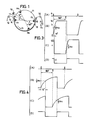
- a rotary plate 11 such as a rotary drum or a head disc plate, is mounted with rotary heads H 1 and H 2 for recording and normal reproduction, at mutually opposing positions in a diametral direction thereof.
- the rotary body 11 is also mounted with rotary heads H A and H B for special reproduction, at mutually opposing positions in a diametral direction thereof.
- the rotary heads H A and H B lag the respective rotary heads H l and H 2 by an angle of 60°, for example.
- the rotary heads H and H B have gaps with an azimuth angle which is the same as the azimuth angle of the gap of one of the rotary heads H 1 and H 2 .
- the track widths of the rotary heads H and H B are greater than the track widths of the rotary heads H 1 and H 2 .
- a magnetic tape 12 is wrapped around the outer peripheral surface of the rotary body 11 over an angular range which is greater than 180°, under the guidance of guide poles 13 through 16. As is well known, the tape 12 is driven in a state pinched between a capstan (not shown) and a pinch roller (not shown). The tape 12 moves in the direction of an arrow X 2 during a recording, a normal reproduction, and a forward special reproduction. The tape 12 moves in the direction of an arrow X 3 during a reverse special reproduction. Further, the movement of the tape 12 is stopped during the still picture reproduction.
- Another rotary body which rotates unitarily with the rotary body 11, comprises magnets 17 and 18 which is fixed at mutually opposing positions in a diametral direction of this other rotary body.
- the magnet 17 has an N-pole exposed at the outer peripheral surface of the other rotary body
- the magnet 18 has an S-pole exposed at the outer peripheral surface of the other rotary body.
- a single stationary pickup head 19 is arranged at a position so that the magnets 17 and 18 will successively oppose the pickup head 19 as the other rotary body rotates unitarily with the rotary body 11.
- the pickup head 19 produces a pulse every time each of the magnets 17 and 18 passes by the pickup head 19. For example, the pickup head 19 produces a positive polarity pulse when the magnet 17 passes by the pickup head 19, and produces a negative polarity pulse when the magnet 18 passes by the pickup head 19.
- the pickup head 19 lags the magnet 17 by 12° in the rotating direction X 1 , so as to be in conformance with an existing standard. Accordingly, as will be described later on in the specification, the output pulse of the pickup head 19 is formed into a switching signal by electrically delaying the output pulse by a delay time corresponding to the rotational period of approximately 12° from the time when the pickup head 19 detects the magnet 17 or 18, during the recording or normal reproduction in which the rotary heads H 1 and H 2 are used. The output pulse of the pickup head 19 is delayed in monostable multivibrators in a phase control system of a head servo circuit.
- the switching signal is used to switch signals which are reproduced by the rotary heads H 1 and H 2 so as to obtain a continuous reproduced signal.
- the rotary heads H A and H B are used during the special reproduction, and the physical switching point of the signals reproduced by the rotary heads H A and H B must be correct.
- the output pulse of the pickup head 19 is electrically delayed by a delay time which is equal to a time it takes for the rotary head H A or H B to start scanning over the tape 12 from the time when the pickup head 19 detects the magnet 17 or 18, so as to obtain the switching signal.
- This delay time is equal to a time it takes for the rotary body 11 to rotate over an angle of approximately 72° from the time when the pickup head 19 detects the magnet 17 or 18.
- monostable multivibrators are used to electrically delay the output pulse of the pickup head 19 and obtain the switching circuit.
- the delay times of the monostable multivibrators are switched by switching the time constants of time constant circuits of the monostable multivibrators, between the normal reproduction and the special reproduction.
- the rotary body 11 which is mounted with the rotary heads H 1 and H 2 , rotates at a rotational speed of 30 rps, and during the normal reproduction, the delay times of the monostable multivibrators are set to a time it takes for the rotary heads H 1 and H 2 to rotate over 12°.
- the delay times of the monostable multivibrators during the normal reproduction can be described by (1/30)x(12/360)x10 3 - 1.1 msec.
- the delay times of the monostable multivibrators are set to a time it takes for the rotary heads H A and H B to rotate over 72°.
- a phase locked loop (PLL) in the phase control system of the head servo system is cut off.
- PLL phase locked loop
- a voltage in accordance with the rotational speed of a capstan motor is obtained as an output signal of the phase control system and is supplied to a motor (head motor) which rotates the rotary body 11.
- the rotational speed of the head motor is controlled so that the frequency of the reproduced horizontal synchronizing signal within the reproduced video signal which is obtained during the special reproduction, is equal to the regular horizontal synchronizing signal frequency.
- the rotational speed of the head motor changes within a large range compared to the rotational speed of the head motor employed during the normal reproduction, as the reproducing speed (tape speed) increases.
- the rotational speed of the head motor undergoes a change within a large range which is over 5.7% of the rotational speed of the head motor employed during the normal reproduction.
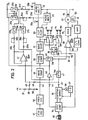
- the reproduced signal switching circuit of the present invention is designed to eliminate the problems described heretofore, and an embodiment of the reproduced signal switching circuit according to the present invention will now be described in conjunction with FIG.l.
- a head motor 20 rotates the rotary body 11 shown in FIG.l.
- the rotational phase of the head motor 20 is detected by the pickup head 19 which cooperates with the magnets 17 and 18.
- a rotational phase detection pulse signal a shown in FIG.3(A) produced from the pickup head 19, is supplied to monostable multivibrators 21 and 22.
- the monostable multivibrator 21 is triggered responsive to a positive polarity pulse
- the monostable multivibrator 22 is triggered responsive to a negative polarity pulse. Pulse signals are alternately obtained from the monostable multivibrators 21 and 22 for every one-half revolution of the head motor 20.
- the pulses in the output pulse signals of the monostable multivibrators 21 and 22 have widths determined by respective time constant circuits of the monostable multivibrators 21 and -22.
- the time constant circuit of the monostable multivibrator 21 is made up of resistors 23a and 29a, variable resistors 24a and 28a, switching circuits 25a and 27a, and a capacitor 26a.
- the time constant circuit of the monostable multivibrator 23 is made up of resistors 23b and 29b, variable resistors 24b and 28b, switching circuits 25b and 27b, and a capacitor 26b.
- the output pulse signals of the monostable multivibrators 21 and 22 are respectively supplied to a flip-flop 30.
- the flip-flop 30 produces a signal which changes its level between a high level and a low level, when output pulse signals of the monostable multivibrators 21 and 22 rise to a predetermined level (Vcc/2).
- the output signal of the flip-flop 30 is a square wave signal having a frequency (30 Hz when the video signal is of the NTSC system) which is 1/2 the frequency of the vertical synchronizing signal of the video signal.
- the output signal of the flip-flop 30 is subjected to a wave-shaping in a wave shaping circuit 31, and is then supplied to one input terminal of a phase comparator 32.
- the output signal of the flip-flop 30 is supplied to switching circuits 33 and 34 as a switching signal.
- the switching circuit 33 switches the signals reproduced by the rotary heads H 1 and H 2
- the switching circuit 34 switches the signals reproduced by the rotary heads H A and H B .
- the switching circuit 33 selectively and alternately produces the signals reproduced by the rotary heads H 1 and H 2 , for every one track scanning period (period of one field), and supplies the produced signal to a terminal N of a head selection switching circuit 35.
- the switching circuit 34 selectively and alternately produces the signals reproduced by the rotary heads H and H B , for every one track scanning period (period of one field), and supplies the produced signal to a terminal S of the head selection switching circuit 35.
- the head selection switching circuit 35 is switched responsive to a switching signal which is received from a system controller 54 through a terminal 50, so that the head selection switching circuit 35 is connected to the terminal N during the normal reproduction and is connected to the terminal S during the special reproduction. Accordingly, during the normal reproduction, the head selection switching circuit 35 produces a time-sequentially multiplexed signal made up of the signals reproduced by the rotary heads H 1 and H 2 . On the other hand, during the special reproduction, the head selection switching circuit 35 produces a time-sequentially multiplexed signal made up of the signals reproduced by the rotary heads H and H B . The signal produced from the head selection switching circuit 35, is obtained through an output terminal 36.
- a resistor 37 has one terminal thereof connected to an input terminal of a positive D.C. voltage source +Vc, and the other terminal thereof grounded through a variable resistor 38 and a resistor 39 which are connected in series.
- This voltage from the slider of the variable resistor 38 is passed through a mixing resistor 40, and is supplied to a non-inverting input terminal of an operational amplifier 41 which constitutes a voltage follower.
- the signal applied to the input terminal 42 is converted into a trapezoidal wave in a wave shaping circuit 43.
- An output trapezoidal wave of the wave shaping circuit 43 is supplied to the other input terminal of the phase comparator 32 wherein the phase of the trapezoidal wave is compared with the phase of the output signal of the wave shaping circuit 31.
- An error voltage which is in accordance with the phase difference between the two signals, is produced from the phase comparator 32. This error voltage is supplied to a switching circuit 46.
- the vertical synchronizing signal can be separated from the video signal or from an external signal.
- the system controller 54 supplies a high-level switching signal to an input terminal 44.
- the system controller 54 supplies a low-level switching signal to the input terminal 44.
- the switching signal supplied to the input terminal 44 is supplied to the switching circuits 27a, 27b, and 47. Further, the switching signal supplied to the input terminal 44, is also supplied to the switching circuits 25a, 25b, and 46, through an inverter 48.
- the system controller 54 supplies a search instruction signal and an instruction signal which is in accordance with the reproducing speed of the special reproduction, to a capstan servo circuit 55.
- the capstan servo circuit 55 rotates a capstan motor 56 at a rotational speed which is in accordance with the instruction signals received from the system controller 54.
- a frequency generator 57 generates a signal having a frequency which is in accordance with the rotational speed of the capstan motor 56.
- the output signal of the frequency generator 57 is supplied to the capstan servo circuit 55 wherein the signal is converted into a voltage which is dependent on ..
- the frequency of the signal and this voltage is converted into a predetermined voltage by being passed through a circuit which is made up of an operational amplifier and resistors within the capstan servo circuit 55.
- the predetermined voltage produced from the capstan servo circuit 55 is supplied to a terminal 45.
- the predetermined voltage supplied to the terminal 45 is supplied to a switching circuit 47, and is also supplied to a non-inverting input terminal of the operational amplifier 41 through a mixing resistor 49.
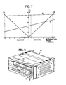
- the special reproduction changing dial 53 is rotatably provided on a front panel of a recording and reproducing apparatus 70 shown in FIG.8.
- a cassette inserting part 71, a power source switch 72, and other predetermined manipulating buttons or switches are arranged at the front of the recording and reproducing apparatus 70.
- the switching circuits 25a, 25b, 27a, 27b, 46, and 47 are designed so that these switches are turned ON responsive to a high-level switching signal and are turned OFF responsive to a low-level switching circuit. Accordingly, when the mode of the recording and reproducing apparatus 70 is set to the special reproduction mode, the switching circuits 27a, 27b, and 47 are turned ON and the switching circuits 25a, 25b, and 46 are turned OFF, because a high-level switching signal is applied to the input terminal 44 in this mode. When the switching circuit 46 is turned OFF, the transmission of the output error voltage of the phase comparator 32 is blocked. Further, when the switching circuit 47 is turned ON, the predetermined voltage applied to the input terminal 45, is passed through the switching circuit 47 and is supplied to a non-inverting input terminal of a mixing amplifier 58 as an output signal of the phase control system.
- a rotation detection signal having a frequency which is proportional to the rotational speed of the head motor 20, is generated from a frequency generator 60.
- the output rotation detection signal of the frequency generator 60 is passed through an amplifier 61 and is supplied to a frequency-to-voltage (F/V) converter 62.
- the F/V converter 62 converts the output signal of the amplifier 61 into a rotational speed detection voltage which is in accordance with the rotational speed of the head motor 20.
- This rotational speed detection voltage is supplied to an inverting input terminal of the mixing amplifier 58 as an output signal of the speed control system.
- the voltages which are mixed and amplified in the mixing amplifier 58, and an output voltage of the mixing amplifier 58 is supplied to a motor driving amplifier (MDA) 59 wherein the voltage is converted into a specific voltage.
- MDA motor driving amplifier
- the output voltage of the MDA 59 is applied to the head motor 20, and the rotational speed and the rotational phase of the head motor 20 are accordingly controlled.
- the rotation of the head motor 20 is controlled so that the Erequency of the horizontal synchronizing signal within the video signals reproduced by the rotary heads H A and H B becomes equal to the regular horizontal synchronizing signal frequency which is constant.
- a low-level switching signal is applied to the terminal 44.
- the switching circuits 27a, 27b, and 47 are turned OFF.
- the switching circuits 25a, 25b, and 46 are turned ON because a high-level signal is applied thereto from the inverter 48.
- the rotational phase of the nead motor 20 is controlled by the output error voltage of the phase comparator 32 so that the head motor 20 rotates at a predetermined rotational speed.
- the time constant circuit of the monostable multivibrator 21 is constituted by the resistors 23a and 24a and the capacitor 26a
- the time constant circuit of the nonostable multivibrator 22 is constituted by the resistors 23b and 24b and the capacitor 26b.
- the reproducing speed corresponds to a forward one-times speed.
- a voltage on a line Ia in FIG.7 for the one-times speed is obtained as the voltage which is obtained by subjecting the output signal of the frequency generator 57 to the frequency-to-voltage conversion.
- a voltage on a line II in FIG.7 for the one-times speed is applied to the terminal 45 from the capstan servo circuit 55.
- the voltage applied to the terminal 45 is subjected to a voltage division by the resistors 40 and 49, and a divided voltage is added with a divided voltage which is obtained by dividing the voltage from the variable resistor 38 by the resistors 40 and 49.
- An added voltage which is obtained by adding the two divided voltages is supplied to the non-inverting input terminal of the operational amplifier 41. Accordingly, a voltage on a line III in FIG.7 for the one-times speed, is produced from the operational amplifier 41.
- the rising times of the output signals of the monostable multivibrators 21 and 22 shown in FIGS.3(B) and 3(C), are determined by the time constant circuits of the monostable multivibrators 21 and 22.
- a time interval between a positive polarity pulse and a negative polarity pulse of the pulse signal a is equal to a time it takes for the rotary body 11 to rotate over an angle of 180°.
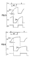
- the special reproduction changing dial 53 is rotated so that an indicator assumes the position for the still picture reproduction.
- a high-level switching signal is supplied to the terminal 44 from the system controller 54.
- the switching circuits 27a, 27b, and 47 are turned ON, and the switching circuits 25a, 25b, and 46 are turned OFF.
- the switching circuit 46 is turned OFF and the switching circuit 47 is turned ON, the transmission of the signal from the phase control system to the head motor 20 is blocked. Consequently, the head motor 20 is rotated responsive to a signal which is in accordance with the rotation of the capstan motor 56, which capstan motor 56 is rotated by the system controller 54 and the capstan servo circuit 55.
- the switching circuits 25a and 25b are turned OFF and the switching circuits 27a and 27b are turned ON, the time constant circuit of the monostable multivibrator 21 is constituted by the resistors 23a, 24a, 28a, and 29a and the capacitor 26a, and the time constant circuit of the monostable multivibrator 22 is constituted by the resistors 23b, 24b, 28b, and 29b and the capacitor 26b.
- the reproducing speed is zero in FIG.7, and the output of the frequency generator 57 is zero.
- a voltage on the line II in FIG.7 for the zero reproducing speed is applied to the terminal 45 from the capstan servo circuit 55.
- the voltage applied to the terminal 45 is subjected to a voltage division by the resistors 40 and 49, and a divided voltage is added with a divided voltage which is obtained by dividing the voltage from the variable resistor 38 by the resistors 40 and 49.
- An added voltage which is obtained by adding the two divided voltages, is supplied to the non-inverting input terminal of the operational amplifier 41.
- the output signal waveforms of the monostable multivibrators 21 and 22 shown in FIGS.4(B) and 4(C) are determined by the time constant circuits of the monostable multivibrators 21 and 22.
- a time required for the output signals of the monostable multivibrators 21 and 22 to rise to a voltage Vcc/2, is equal to the time it takes for the rotary body 11 to rotate over an angle of 72°.
- the switching signal shown in FIG.4(D) is produced from the flip-flop 30.
- the special reproduction changing dial 53 is rotated so that the indicator assumes a position for the ten-times speed reproduction.
- the capstan motor 56 is rotated by the system controller 54 and the capstan servo circuit 55, at a rotational speed which is in accordance with the forward ten-times speed reproduction.
- a voltage on the line Ia in FIG.7 for the forward ten-times speed is produced from the frequency generator 57.
- a voltage on the line II in FIG.7 for the forward ten-times speed is applied to the terminal 45.
- the voltage applied to the terminal 45 is subjected to a voltage division by the resistors 40 and 49, and a divided voltage is added with a divided voltage which is obtained by dividing the voltage from the variable resistor 38 by the resistors 40 and 49.
- An added voltage which is obtained by adding the two divided voltages is supplied to the non-inverting input terminal of the operational amplifier 41. Accordingly, the voltage applied to the time constant circuits of the monostable multivibrators 21 and 22, is higher than the voltage applied to the time constant circuits during the still picture reproduction.
- the rises in the output signals of the monostable multivibrators 21 and 22 are more steep than the rises in the output signals during the still picture reproduction, as may be seen from FIGS.5(B) and 5(C).
- the time required for the output signals of the monostable multivibrators 21 and 22 to reach the predetermined voltage Vcc/2 is shorter than the time required during the still picture reproduction. For this reason, even when the rotational speed of the rotary body 11 becomes faster than the rotational speed during the still picture reproduction, the correct switching signal shown in FIG.5(D) is obtained so as to switch the reproduced signals when the rotary body 11 rotates over the angle of 72° from the time when the pickup head 19 produces the pulse shown in FIG.5(A).
- the special reproduction changing dial 53 is rotated so that the indicator assumes a position for the reverse ten-times speed reproduction.
- the capstan motor 56 is rotated in a reverse direction, and the tape 12 is moved in the reverse direction.
- a voltage on a line Ib in FIG.7 for the reverse ten-times speed is produced from the frequency generator 57.
- a voltage on the line II in FIG.7 for the reverse ten-times speed is applied to the terminal 45 from the capstan servo circuit 55. Accordingly, a voltage on the line III in FIG.7 for the reverse ten-times speed, is produced from the operational amplifier 41.
- the output voltage of the operational amplifier 41 is smaller than the output voltage during the still picture reproduction.
- the rises in the output signals of the monostable multivibrators 21 and 22 are more gradual compared to the rises in the output signals during the still picture reproduction, as may be seen from FIGS.6(B) and 6(C).
- the delay times of the monostable multivibrators 21 and 22, that is, the time it takes for the output signals of the monostable multivibrators 21 and 22 to rise to the predetermined voltage Vcc/2 responsive to the output pulse signal of the pickup head 19, are equal to the time it takes for the rotary body 11 to rotate over the angle of 72°.
- the delay times of the monostable multivibrators 21 and 22 are set to 6.72 msec during the still picture reproduction, 6.3 msec during the forward ten-times speed reproduction, and 7.1 msec during the reverse ten-times speed reproduction.
Landscapes
- Television Signal Processing For Recording (AREA)
- Adjustment Of The Magnetic Head Position Track Following On Tapes (AREA)
Applications Claiming Priority (2)
| Application Number | Priority Date | Filing Date | Title |
|---|---|---|---|
| JP58177529A JPS6069975A (ja) | 1983-09-26 | 1983-09-26 | 変速再生時における回転ヘツドの再生信号切換回路 |
| JP177529/83 | 1983-09-26 |
Publications (3)
| Publication Number | Publication Date |
|---|---|
| EP0138457A2 true EP0138457A2 (fr) | 1985-04-24 |
| EP0138457A3 EP0138457A3 (en) | 1986-02-12 |
| EP0138457B1 EP0138457B1 (fr) | 1989-08-09 |
Family
ID=16032515
Family Applications (1)
| Application Number | Title | Priority Date | Filing Date |
|---|---|---|---|
| EP84306560A Expired EP0138457B1 (fr) | 1983-09-26 | 1984-09-26 | Circuit de commutation de signal de reproduction pour appareil de reproduction comportant des têtes rotatives pour reproduction spéciale |
Country Status (6)
| Country | Link |
|---|---|
| US (1) | US4630136A (fr) |
| EP (1) | EP0138457B1 (fr) |
| JP (1) | JPS6069975A (fr) |
| KR (1) | KR900001524B1 (fr) |
| CA (1) | CA1250047A (fr) |
| DE (2) | DE3479376D1 (fr) |
Cited By (3)
| Publication number | Priority date | Publication date | Assignee | Title |
|---|---|---|---|---|
| EP0170246A1 (fr) * | 1984-07-30 | 1986-02-05 | Hitachi, Ltd. | Appareil pour la reproduction de signaux vidéo |
| DE3616726A1 (de) * | 1985-05-20 | 1986-11-20 | Victor Company Of Japan, Ltd., Yokohama, Kanagawa | Schaltung zum erzeugen eines kopfumschaltsignals |
| GB2226686A (en) * | 1988-12-31 | 1990-07-04 | Samsung Electronics Co Ltd | Multifunctional control type video head selecting |
Families Citing this family (7)
| Publication number | Priority date | Publication date | Assignee | Title |
|---|---|---|---|---|
| JPS61273740A (ja) * | 1985-05-28 | 1986-12-04 | Matsushita Electric Ind Co Ltd | ダビング用磁気再生装置 |
| US4796103A (en) * | 1985-06-03 | 1989-01-03 | Victor Company Of Japan Ltd. | Control pulse recording circuit for dual tape speed recording and reproducing apparatuses using two pairs of heads selectively for selected speed including recording delayed control pulses |
| JPS61284820A (ja) * | 1985-06-11 | 1986-12-15 | Alps Electric Co Ltd | ヘツド位置制御方法 |
| JP2557842B2 (ja) * | 1986-03-31 | 1996-11-27 | 株式会社東芝 | 回転ヘツドの回転位相発生装置 |
| JPS6469173A (en) * | 1987-09-10 | 1989-03-15 | Mitsubishi Electric Corp | Video signal recording and reproducing device |
| JPS6469172A (en) * | 1987-09-10 | 1989-03-15 | Mitsubishi Electric Corp | Video signal recording and reproducing device |
| JPH04109419A (ja) * | 1990-08-29 | 1992-04-10 | Unitec Denshi Kk | ダブルアジマス4ヘッド型ビデオテープレコーダの変速再生補償装置 |
Family Cites Families (9)
| Publication number | Priority date | Publication date | Assignee | Title |
|---|---|---|---|---|
| JPS52109815U (fr) * | 1976-02-18 | 1977-08-20 | ||
| JPS53115131A (en) * | 1977-03-17 | 1978-10-07 | Matsushita Electric Ind Co Ltd | Magnetic picture recording/reproducing system |
| JPS585444B2 (ja) * | 1978-02-10 | 1983-01-31 | 三菱電機株式会社 | 磁気記録再生装置 |
| DE3173723D1 (en) * | 1980-10-03 | 1986-03-20 | Matsushita Electric Industrial Co Ltd | Video tape recording/reproducing apparatus |
| JPS5797282A (en) * | 1980-12-09 | 1982-06-16 | Matsushita Electric Ind Co Ltd | Magnetic recording and reproducing device |
| JPS57162892A (en) * | 1981-03-31 | 1982-10-06 | Matsushita Electric Ind Co Ltd | Magnetic recorder and reproducer |
| US4490755A (en) * | 1981-07-09 | 1984-12-25 | Victor Company Of Japan, Ltd. | Recording and reproducing video signals at selectable different tape traveling speeds from plural video head pairs |
| JPS5843077U (ja) * | 1981-09-17 | 1983-03-23 | 日本ビクター株式会社 | ヘツド切換回路 |
| JPS5936487A (ja) * | 1982-08-24 | 1984-02-28 | Matsushita Electric Ind Co Ltd | 磁気再生装置 |
-
1983
- 1983-09-26 JP JP58177529A patent/JPS6069975A/ja active Granted
-
1984
- 1984-09-18 KR KR1019840005681A patent/KR900001524B1/ko not_active Expired
- 1984-09-19 CA CA000463612A patent/CA1250047A/fr not_active Expired
- 1984-09-20 US US06/652,523 patent/US4630136A/en not_active Expired - Lifetime
- 1984-09-26 DE DE8484306560T patent/DE3479376D1/de not_active Expired
- 1984-09-26 DE DE198484306560T patent/DE138457T1/de active Pending
- 1984-09-26 EP EP84306560A patent/EP0138457B1/fr not_active Expired
Cited By (7)
| Publication number | Priority date | Publication date | Assignee | Title |
|---|---|---|---|---|
| EP0170246A1 (fr) * | 1984-07-30 | 1986-02-05 | Hitachi, Ltd. | Appareil pour la reproduction de signaux vidéo |
| US4675752A (en) * | 1984-07-30 | 1987-06-23 | Hitachi, Ltd. | Apparatus for recording and/or reproducing video signals |
| DE3616726A1 (de) * | 1985-05-20 | 1986-11-20 | Victor Company Of Japan, Ltd., Yokohama, Kanagawa | Schaltung zum erzeugen eines kopfumschaltsignals |
| US4706137A (en) * | 1985-05-20 | 1987-11-10 | Victor Company Of Japan, Ltd. | Head switching signal producing circuit with compensation of a phase error due to the positioning of a rotary drum head and a rotational phase detector |
| GB2226686A (en) * | 1988-12-31 | 1990-07-04 | Samsung Electronics Co Ltd | Multifunctional control type video head selecting |
| GB2226686B (en) * | 1988-12-31 | 1993-04-21 | Samsung Electronics Co Ltd | Multifunctional control type video head selecting device and method thereof |
| US5291342A (en) * | 1988-12-31 | 1994-03-01 | Samsung Electronics Co., Ltd. | Multifunctional control type video head selecting device and method thereof |
Also Published As
| Publication number | Publication date |
|---|---|
| JPS6069975A (ja) | 1985-04-20 |
| US4630136A (en) | 1986-12-16 |
| KR850002538A (ko) | 1985-05-13 |
| EP0138457B1 (fr) | 1989-08-09 |
| KR900001524B1 (ko) | 1990-03-12 |
| DE138457T1 (de) | 1985-09-12 |
| DE3479376D1 (en) | 1989-09-14 |
| EP0138457A3 (en) | 1986-02-12 |
| JPH0155798B2 (fr) | 1989-11-27 |
| CA1250047A (fr) | 1989-02-14 |
Similar Documents
| Publication | Publication Date | Title |
|---|---|---|
| EP0100546B1 (fr) | Contrôle de reproduction à vitesse variable pour un enregistreur à bande vidéo | |
| GB2036407A (en) | System for reproducing video signals in slowmotion mode | |
| US4630136A (en) | Reproduced signal switching circuit for reproducing apparatus having rotary heads for special reproduction | |
| US4521815A (en) | Reproducing apparatus capable of performing high-speed reproduction of a video signal | |
| GB2104703A (en) | Video recording and reproducing apparatus | |
| US4605976A (en) | Recording and/or reproducing system for a 4-head type recording and/or reproducing apparatus | |
| US4361856A (en) | Video tape recorder | |
| JPS644395B2 (fr) | ||
| US4539606A (en) | Magnetic reproducing apparatus having a capstan servo circuit | |
| US3942084A (en) | Video tape recorder method and apparatus | |
| GB2096801A (en) | Tracking control system in a magnetic recording and reproducing apparatus | |
| EP0043739A1 (fr) | Système d'alignement | |
| US4649439A (en) | System for reproducing a video signal in a still picture reproduction | |
| US4086520A (en) | Speed and phase control system | |
| US4145642A (en) | System for controlling the rotation of a DC motor | |
| EP0326255A2 (fr) | Dispositif d'asservissement d'un moteur | |
| US4751586A (en) | Rotary head tape transport servo system having high speed servo lock capability | |
| KR940006392B1 (ko) | 비디오 레코더 | |
| JPH0648861B2 (ja) | 映像信号再生装置 | |
| JPS56166678A (en) | Magnetic video recording and reproducing device | |
| EP0119200B1 (fr) | Appareil d'enregistrement et de reproduction video pour le reglage du deplacement de bande | |
| EP0337582B1 (fr) | Système d'asservissement pour enregistreur vidéo pouvant se verrouiller à grande vitesse sur une piste de commande | |
| KR920009099B1 (ko) | 타코 펄스발생회로 | |
| JPS5822276Y2 (ja) | ヘツドサ−ボ装置 | |
| JPS5922433B2 (ja) | 映像信号の磁気再生装置 |
Legal Events
| Date | Code | Title | Description |
|---|---|---|---|
| PUAI | Public reference made under article 153(3) epc to a published international application that has entered the european phase |
Free format text: ORIGINAL CODE: 0009012 |
|
| AK | Designated contracting states |
Designated state(s): DE FR GB |
|
| EL | Fr: translation of claims filed | ||
| 17P | Request for examination filed |
Effective date: 19850613 |
|
| DET | De: translation of patent claims | ||
| PUAL | Search report despatched |
Free format text: ORIGINAL CODE: 0009013 |
|
| RHK1 | Main classification (correction) |
Ipc: H04N 5/783 |
|
| AK | Designated contracting states |
Designated state(s): DE FR GB |
|
| 17Q | First examination report despatched |
Effective date: 19880225 |
|
| GRAA | (expected) grant |
Free format text: ORIGINAL CODE: 0009210 |
|
| AK | Designated contracting states |
Kind code of ref document: B1 Designated state(s): DE FR GB |
|
| REF | Corresponds to: |
Ref document number: 3479376 Country of ref document: DE Date of ref document: 19890914 |
|
| ET | Fr: translation filed | ||
| PLBE | No opposition filed within time limit |
Free format text: ORIGINAL CODE: 0009261 |
|
| STAA | Information on the status of an ep patent application or granted ep patent |
Free format text: STATUS: NO OPPOSITION FILED WITHIN TIME LIMIT |
|
| 26N | No opposition filed | ||
| PGFP | Annual fee paid to national office [announced via postgrant information from national office to epo] |
Ref country code: FR Payment date: 19950911 Year of fee payment: 12 |
|
| PGFP | Annual fee paid to national office [announced via postgrant information from national office to epo] |
Ref country code: GB Payment date: 19950918 Year of fee payment: 12 |
|
| PGFP | Annual fee paid to national office [announced via postgrant information from national office to epo] |
Ref country code: DE Payment date: 19950928 Year of fee payment: 12 |
|
| PG25 | Lapsed in a contracting state [announced via postgrant information from national office to epo] |
Ref country code: GB Effective date: 19960926 |
|
| PG25 | Lapsed in a contracting state [announced via postgrant information from national office to epo] |
Ref country code: FR Effective date: 19960930 |
|
| GBPC | Gb: european patent ceased through non-payment of renewal fee |
Effective date: 19960926 |
|
| PG25 | Lapsed in a contracting state [announced via postgrant information from national office to epo] |
Ref country code: DE Effective date: 19970603 |
|
| REG | Reference to a national code |
Ref country code: FR Ref legal event code: ST |
|
| REG | Reference to a national code |
Ref country code: FR Ref legal event code: ST |