EP0135655B1 - Hydraulische Steuerung für Extruder-Spritzaggregate zum Verarbeiten von Kautschuk - Google Patents
Hydraulische Steuerung für Extruder-Spritzaggregate zum Verarbeiten von Kautschuk Download PDFInfo
- Publication number
- EP0135655B1 EP0135655B1 EP84104048A EP84104048A EP0135655B1 EP 0135655 B1 EP0135655 B1 EP 0135655B1 EP 84104048 A EP84104048 A EP 84104048A EP 84104048 A EP84104048 A EP 84104048A EP 0135655 B1 EP0135655 B1 EP 0135655B1
- Authority
- EP
- European Patent Office
- Prior art keywords
- pressure
- piston
- working cylinder
- dynamic pressure
- injection
- Prior art date
- Legal status (The legal status is an assumption and is not a legal conclusion. Google has not performed a legal analysis and makes no representation as to the accuracy of the status listed.)
- Expired
Links
Images

Classifications
-
- B—PERFORMING OPERATIONS; TRANSPORTING
- B29—WORKING OF PLASTICS; WORKING OF SUBSTANCES IN A PLASTIC STATE IN GENERAL
- B29C—SHAPING OR JOINING OF PLASTICS; SHAPING OF MATERIAL IN A PLASTIC STATE, NOT OTHERWISE PROVIDED FOR; AFTER-TREATMENT OF THE SHAPED PRODUCTS, e.g. REPAIRING
- B29C45/00—Injection moulding, i.e. forcing the required volume of moulding material through a nozzle into a closed mould; Apparatus therefor
- B29C45/17—Component parts, details or accessories; Auxiliary operations
- B29C45/76—Measuring, controlling or regulating
- B29C45/77—Measuring, controlling or regulating of velocity or pressure of moulding material
-
- B—PERFORMING OPERATIONS; TRANSPORTING
- B29—WORKING OF PLASTICS; WORKING OF SUBSTANCES IN A PLASTIC STATE IN GENERAL
- B29C—SHAPING OR JOINING OF PLASTICS; SHAPING OF MATERIAL IN A PLASTIC STATE, NOT OTHERWISE PROVIDED FOR; AFTER-TREATMENT OF THE SHAPED PRODUCTS, e.g. REPAIRING
- B29C45/00—Injection moulding, i.e. forcing the required volume of moulding material through a nozzle into a closed mould; Apparatus therefor
- B29C45/17—Component parts, details or accessories; Auxiliary operations
- B29C45/46—Means for plasticising or homogenising the moulding material or forcing it into the mould
- B29C45/53—Means for plasticising or homogenising the moulding material or forcing it into the mould using injection ram or piston
- B29C45/54—Means for plasticising or homogenising the moulding material or forcing it into the mould using injection ram or piston and plasticising screw
-
- B—PERFORMING OPERATIONS; TRANSPORTING
- B29—WORKING OF PLASTICS; WORKING OF SUBSTANCES IN A PLASTIC STATE IN GENERAL
- B29C—SHAPING OR JOINING OF PLASTICS; SHAPING OF MATERIAL IN A PLASTIC STATE, NOT OTHERWISE PROVIDED FOR; AFTER-TREATMENT OF THE SHAPED PRODUCTS, e.g. REPAIRING
- B29C45/00—Injection moulding, i.e. forcing the required volume of moulding material through a nozzle into a closed mould; Apparatus therefor
- B29C45/17—Component parts, details or accessories; Auxiliary operations
- B29C45/76—Measuring, controlling or regulating
- B29C45/82—Hydraulic or pneumatic circuits
-
- B—PERFORMING OPERATIONS; TRANSPORTING
- B29—WORKING OF PLASTICS; WORKING OF SUBSTANCES IN A PLASTIC STATE IN GENERAL
- B29C—SHAPING OR JOINING OF PLASTICS; SHAPING OF MATERIAL IN A PLASTIC STATE, NOT OTHERWISE PROVIDED FOR; AFTER-TREATMENT OF THE SHAPED PRODUCTS, e.g. REPAIRING
- B29C2948/00—Indexing scheme relating to extrusion moulding
- B29C2948/92—Measuring, controlling or regulating
- B29C2948/92819—Location or phase of control
- B29C2948/92961—Auxiliary unit, e.g. for external melt filtering, re-combining or transfer between units
Definitions
- the invention relates to a hydraulic control for extruder injection units for processing rubber, with a plasticizing unit driven by a hydraulic motor and an injection unit with a hydraulic working cylinder whose piston rod is connected to the injection piston, and with a hydraulic pump for the hydraulic motor and the working cylinder depending on the spray pressure and / or the spray speed, the holding pressure and the dynamic pressure is controlled.
- Extruder injection units for processing rubber have an extruder for plasticizing the rubber to be processed, which takes place under a predetermined dynamic pressure, the rubber to be plasticized heating up as a result of the friction work. Since rubber compounds have a certain reaction temperature, regardless of the elastomer, care must be taken that this temperature is not exceeded.
- the extruder In general, it is common for the extruder to convey the plasticized rubber into an injection cylinder, from which it is injected into the mold by means of an injection piston.
- the extruder injection unit is in some cases designed so that a screw takes on both the plasticizing function and the spraying function.
- the invention has for its object to provide a hydraulic control of the type mentioned, which takes into account these changing influences by the vulcanized films in the annular gap, so that the dynamic pressure phase takes place under a constant, predetermined dynamic pressure.
- a transducer for the position of the piston rod of the working cylinder or the injection piston a pressure control valve which can be connected to the line leading to the pressure chamber of the working cylinder for piston retraction, a proportionally controlled pressure valve which can be connected to the line leading to the pressure cylinder of the working cylinder for the piston feed, a device for controlling the proportionally controlled pressure valve as a function of decreasing control values and a device which, when the output signal on the sensor changes for the first time, adds the instantaneous value of the pressure in the pressure chamber to the preselected back pressure as a correction variable at the beginning of each stand pressure phase.
- the switchable pressure control valve goes into the working position and establishes the connection between the other pressure chamber of the working cylinder and the pressure connection line.
- a sufficiently large maximum pressure is set here.
- the pressure chamber of the working cylinder is connected to the drain connection line, the pressure being predetermined by the pressure set at the proportionally controlled pressure valve, which is intended by its control device falling tax values is controlled.
- the piston moves with the piston rod.
- the output signal of the transducer changes, which is fed to the device. The pressure difference present when this signal changes causes the device to add this pressure difference as a correction value to the specified dynamic pressure.
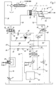
- the extruder injection unit consists of the plasticizing unit 1 and the injection unit 2.
- the plasticizing unit has a screw 4 rotatably mounted in a cylinder 3, to which the rubber material to be plasticized is fed via a funnel 5.
- the screw is driven by a hydraulic motor 6, which is acted upon by a controlled pump 7.
- This controlled pump 7 is controlled as a function of the injection pressure and holding pressure.
- the injection unit 2 has an injection cylinder 8 with an injection piston 9 guided axially displaceably therein.
- This injection piston is coupled to the piston rod 10 of the working cylinder 11, the piston 12 of which limits the pressure spaces 13 and 14 with the working cylinder.
- the injection cylinder is connected to the extruder via a line 15, in which a check valve 16 is arranged.
- the injection cylinder also has a check valve 17.
- the rotating screw feeds plasticized material with the check valve 16 open and the shut-off valve 17 closed, the material being fed into the injection cylinder, the injection piston moving towards its left end position in the drawing.
- the valve 17 is opened and the plasticized rubber material is injected in the direction of the arrow into the shape (not shown), the check valve 16 being closed by the injection pressure which builds up.
- a line 19 leads via a proportional valve 20 to the inlet 21 of a 4/3-way valve 25. Its first outlet 23 leads via a line 26 to the hydraulic motor 6. In line 19 is at the branch 27 between the Proportional valve 20 and the 4/3-way valve 25, the pressure connection line 28 connected.
- a further branch 29 is provided in the line 19 for a control line 30, which leads to the tank T via a pressure relief valve 31.
- the control line 33 leads from a branch 32 to the controlled pump 7.
- another branch 34 is provided, which is connected via a line 35 to the first inflow 36 of FIG. 3-way valve 40 is connected.
- the first outlet 38 of this 4/3-way valve is connected to the inlet of a proportionally controlled pressure valve 41, the outlet of which is connected to the branch 42 in the duct 30 between the pressure relief valve 31 and the tank.
- a branch 43 is provided, which is connected to the second outlet 39 of the 4/3-way valve 40.
- the second inlet 37 of this 4/3-way valve leads via a line 44 and a throttle 45 to the third outlet 22 of the 4/3-way valve 25.
- a branch 46 is arranged, which via the line 50 'leads to the pressure relief valve 47, the control line 48 of which is connected to the branch 49 between the throttle 45 and the inflow 37 in the line 44.
- the drain line 50 of this pressure relief valve leads to the tank.
- the second outlet 24 of the 4/3-way valve 25 is connected via a line 51 to the pressure chamber 14 of the working cylinder 11.
- the pressure chamber 13 of the working cylinder for the piston retraction is connected via a line 52 to the second outlet 54 of a 4/2-way valve 55, the first outlet 53 of which is blocked.
- the third drain 52 of this 4/2-way valve is connected to the branch 56 in the drain line 50 of the pressure relief valve 47.
- the inflow 51 of the 4/2-way valve 55 is connected to the branch 58 in the pressure connection line 28 via a pressure control valve 57.
- the injection piston 9 or the piston rod 10 is coupled to a displacement measuring system 59, which can be, for example, an absolute angle encoder, which is coupled to the injection piston or the piston rod via a toothed rack.
- a displacement measuring system 59 which can be, for example, an absolute angle encoder, which is coupled to the injection piston or the piston rod via a toothed rack.
- the device for controlling the proportional Controlled pressure valve 41 is designated 60, in which a pressure curve is stored, according to which the pilot pressure changes according to a predetermined time function.
- the output of the transducer system 59 is connected to an input 61 of the control part 60.
- This control part 60 also has an input 62 for the setpoint of the dynamic pressure.
- Fig. 2 shows the position of the valves for determining the correction value for the dynamic pressure at the beginning of the dynamic pressure phase.
- the device 60 detects the registered instantaneous value of the pressure in the pressure chamber 14 and adds it as a correction value to the dynamic pressure specified as the desired value.
- the back pressure phase then runs under the corrected back pressure.
- the correction value is determined at the beginning of each dynamic pressure phase.
Landscapes
- Engineering & Computer Science (AREA)
- Manufacturing & Machinery (AREA)
- Mechanical Engineering (AREA)
- Injection Moulding Of Plastics Or The Like (AREA)
- Extrusion Moulding Of Plastics Or The Like (AREA)
Priority Applications (1)
| Application Number | Priority Date | Filing Date | Title |
|---|---|---|---|
| AT84104048T ATE28592T1 (de) | 1983-06-07 | 1984-04-11 | Hydraulische steuerung fuer extruderspritzaggregate zum verarbeiten von kautschuk. |
Applications Claiming Priority (2)
| Application Number | Priority Date | Filing Date | Title |
|---|---|---|---|
| DE3320520A DE3320520C1 (de) | 1983-06-07 | 1983-06-07 | Hydraulische Steuerung fuer Extruder-Spritzaggregate zum Verarbeiten von Kautschuk |
| DE3320520 | 1983-06-07 |
Publications (2)
| Publication Number | Publication Date |
|---|---|
| EP0135655A1 EP0135655A1 (de) | 1985-04-03 |
| EP0135655B1 true EP0135655B1 (de) | 1987-07-29 |
Family
ID=6200863
Family Applications (1)
| Application Number | Title | Priority Date | Filing Date |
|---|---|---|---|
| EP84104048A Expired EP0135655B1 (de) | 1983-06-07 | 1984-04-11 | Hydraulische Steuerung für Extruder-Spritzaggregate zum Verarbeiten von Kautschuk |
Country Status (7)
| Country | Link |
|---|---|
| US (1) | US4632651A (enExample) |
| EP (1) | EP0135655B1 (enExample) |
| JP (1) | JPS6011328A (enExample) |
| AT (1) | ATE28592T1 (enExample) |
| DD (1) | DD231033A1 (enExample) |
| DE (1) | DE3320520C1 (enExample) |
| SU (1) | SU1297715A3 (enExample) |
Families Citing this family (10)
| Publication number | Priority date | Publication date | Assignee | Title |
|---|---|---|---|---|
| JPS6225027A (ja) * | 1985-07-25 | 1987-02-03 | Aisin Seiki Co Ltd | 射出成形装置 |
| EP0279081B1 (en) * | 1987-02-16 | 1992-09-30 | Consiglio Nazionale Delle Ricerche | An apparatus and method for controlling the cross-linking of elastomers in a mould |
| JP2657352B2 (ja) * | 1993-09-08 | 1997-09-24 | 日精樹脂工業株式会社 | 射出成形機の圧力検出方法及び装置 |
| JPH09123241A (ja) * | 1995-10-27 | 1997-05-13 | Sodick Co Ltd | スクリュプリプラ式射出成形装置の射出制御方法 |
| JP3423963B2 (ja) * | 1997-12-01 | 2003-07-07 | 新潟鐵工成形機株式会社 | 射出成形機 |
| US6572362B2 (en) | 2001-08-01 | 2003-06-03 | The Goodyear Tire & Rubber Company | Apparatus for injection molding in alternate planes |
| US6604936B2 (en) | 2001-08-01 | 2003-08-12 | The Goodyear Tire & Rubber Company | Apparatus for injection molding |
| DE10154676B4 (de) | 2001-11-07 | 2005-08-18 | Carl Freudenberg Kg | Spritzgießmaschine zur Herstellung von Elastomer- und Duromerformteilen |
| RU2382700C1 (ru) * | 2008-07-15 | 2010-02-27 | Барановичский Станкостроительный Завод Закрытого Акционерного Общества "Атлант" (Бзс Зао "Атлант") | Гидросистема узла впрыска и набора дозы литьевой машины, например термопластавтомата (варианты) |
| JP6177712B2 (ja) * | 2014-02-28 | 2017-08-09 | 住友重機械工業株式会社 | 射出成形機 |
Family Cites Families (10)
| Publication number | Priority date | Publication date | Assignee | Title |
|---|---|---|---|---|
| US3148231A (en) * | 1961-03-20 | 1964-09-08 | Eastman Kodak Co | Plastic extrusion, apparatus and control |
| US3840312A (en) * | 1973-04-11 | 1974-10-08 | Control Process Inc | Dynamic pressure control system |
| US3932083A (en) * | 1973-12-03 | 1976-01-13 | Barber-Colman Company | Injection molding control |
| US4208176A (en) * | 1975-06-16 | 1980-06-17 | Litton Industrial Products, Inc. | Time independent cycle control for plastic injection molding machines |
| US4325896A (en) * | 1975-10-08 | 1982-04-20 | Solid Controls, Inc. | Electro-hydraulic ram control apparatus |
| US4135870A (en) * | 1976-06-03 | 1979-01-23 | Standard Oil Company (Indiana) | Machine for producing additive containing plastic articles |
| DE2725804C2 (de) * | 1977-06-08 | 1986-07-31 | Werner & Pfleiderer, 7000 Stuttgart | Verfahren zum Druckaufbau in einer Presse für eine explosive Masse und Schaltanordnung zum Ausüben des Verfahrens |
| JPS5549238A (en) * | 1978-10-05 | 1980-04-09 | Toshiba Mach Co Ltd | Plasticizing process controlling method for in-line screw type jet-form machine |
| JPS5835460B2 (ja) * | 1979-09-28 | 1983-08-02 | 株式会社日立製作所 | トランスフア成形機 |
| DE3027698A1 (de) * | 1980-07-22 | 1982-02-18 | Isago Asaki Saitama Miura | Spritzgussverfahren und spritzgussvorrichtung |
-
1983
- 1983-06-07 DE DE3320520A patent/DE3320520C1/de not_active Expired
-
1984
- 1984-04-11 AT AT84104048T patent/ATE28592T1/de active
- 1984-04-11 EP EP84104048A patent/EP0135655B1/de not_active Expired
- 1984-05-29 DD DD84263510A patent/DD231033A1/de not_active IP Right Cessation
- 1984-06-04 US US06/617,279 patent/US4632651A/en not_active Expired - Fee Related
- 1984-06-06 SU SU843748946A patent/SU1297715A3/ru active
- 1984-06-07 JP JP59115657A patent/JPS6011328A/ja active Granted
Also Published As
| Publication number | Publication date |
|---|---|
| JPH0133330B2 (enExample) | 1989-07-12 |
| JPS6011328A (ja) | 1985-01-21 |
| EP0135655A1 (de) | 1985-04-03 |
| DD231033A1 (de) | 1985-12-18 |
| US4632651A (en) | 1986-12-30 |
| SU1297715A3 (ru) | 1987-03-15 |
| ATE28592T1 (de) | 1987-08-15 |
| DE3320520C1 (de) | 1984-12-13 |
Similar Documents
| Publication | Publication Date | Title |
|---|---|---|
| DE2148917C3 (de) | Vorrichtung zur optimierenden Einstellung der Drehzahl einer drehbaren und axial verschiebbaren PIastifizierschnecke einer Kunststotfspritzgießmaschine | |
| DE3203763C2 (de) | Plastifizier- und Einspritzeinheit für Spritzgießmaschinen | |
| CH642905A5 (de) | Spritzgiessmaschine. | |
| EP0135655B1 (de) | Hydraulische Steuerung für Extruder-Spritzaggregate zum Verarbeiten von Kautschuk | |
| DE2209355A1 (de) | Spritzpresse | |
| DE3036441A1 (de) | Spritzpressformmaschine | |
| DE2246548A1 (de) | Verfahren und vorrichtung zum verformen und verpressen eines gemisches aus einem hochmolekularen material und einem vernetzungsmittel | |
| DE1554793A1 (de) | Kunststoffspritzgiessmaschine | |
| DE69109614T2 (de) | Verfahren zum feststellen von harzeigenschaften bei einer spritzgiessmaschine. | |
| EP1388404B1 (de) | Hydraulikaggregat für eine Spritzgiessmaschine | |
| DE69305837T3 (de) | Eine hydraulischbetätigte Kolben-Strangpresse | |
| DE2532429C3 (de) | Verfahren und Einrichtung zum Spritzgießen einer Kunststoffmasse mit veränderbarer Einspritzgeschwindigkeit | |
| DE3229810A1 (de) | Vorrichtung zum plastifizieren von kunststoffen | |
| DE2951948A1 (de) | Hydraulische steuervorrichtung fuer die einspritzeinheit einer kunststoff-spritzgiessmaschine zum steuern unterschiedlicher hydraulikdruecke | |
| DE1650785B2 (de) | Vorrichtung fuer die antriebsregelung von spritzgiessmaschinen | |
| DE2523303B2 (de) | Hydraulische steuervorrichtung fuer die einspritzeinheit einer kunststoff- spritzgiessmaschine zum steuern unterschiedlicher hydraulikdruecke | |
| DE2419975C3 (de) | Hydraulische Steuervorrichtung für eine Einspritzeinheit einer Kunststoff-Spritzgießmaschine zum Steuern unterschiedlicher Hydraulikdrücke | |
| AT518422B1 (de) | Speicherbehältnis für eine Formgebungsmaschine | |
| DE3537423A1 (de) | Einrichtung zur druck- und mengenregelung der hydraulischen antriebe einer spritzgiessmaschine | |
| DE2129017C3 (de) | Steuereinrichtung an einer Honmaschine zum gleichzeitigen Bearbeiten von mindestens zwei koaxial hintereinanderliegenden Bohrungen | |
| DE1529959A1 (de) | Schneckenstrangpresse fuer spritzfaehige Massen,z.B. thermoplastische Kunststoffe u.dgl. | |
| EP0171609A2 (de) | Einrichtung zur Steuerung und/oder Begrenzung der Formauftriebskraft an Spritzgiessmaschinen | |
| DE2311404A1 (de) | Einrichtung zur selbsttaetigen schnekkenrueckholung an kunststoffspritzgiessmaschinen | |
| DE2544681A1 (de) | Verfahren zum veraendern des staudrucks bei einer schneckenspritzgiessmaschine und vorrichtung zur durchfuehrung des verfahrens | |
| DE1529752C (de) | Vorrichtung zur Durchfuhrung eines Verfahrens zum volligen oder angenäherten Ausgleichen der axialen Temperaturunter schiede der Masse im Sammelraum einer Schnecken Spritzgießmaschine |
Legal Events
| Date | Code | Title | Description |
|---|---|---|---|
| PUAI | Public reference made under article 153(3) epc to a published international application that has entered the european phase |
Free format text: ORIGINAL CODE: 0009012 |
|
| 17P | Request for examination filed |
Effective date: 19840411 |
|
| AK | Designated contracting states |
Designated state(s): AT FR GB IT SE |
|
| 16A | New documents despatched to applicant after publication of the search report | ||
| 17Q | First examination report despatched |
Effective date: 19860414 |
|
| ITF | It: translation for a ep patent filed | ||
| GRAA | (expected) grant |
Free format text: ORIGINAL CODE: 0009210 |
|
| AK | Designated contracting states |
Kind code of ref document: B1 Designated state(s): AT FR GB IT SE |
|
| REF | Corresponds to: |
Ref document number: 28592 Country of ref document: AT Date of ref document: 19870815 Kind code of ref document: T |
|
| ET | Fr: translation filed | ||
| PLBE | No opposition filed within time limit |
Free format text: ORIGINAL CODE: 0009261 |
|
| STAA | Information on the status of an ep patent application or granted ep patent |
Free format text: STATUS: NO OPPOSITION FILED WITHIN TIME LIMIT |
|
| 26N | No opposition filed | ||
| ITTA | It: last paid annual fee | ||
| EAL | Se: european patent in force in sweden |
Ref document number: 84104048.8 |
|
| PGFP | Annual fee paid to national office [announced via postgrant information from national office to epo] |
Ref country code: SE Payment date: 19960112 Year of fee payment: 13 |
|
| PGFP | Annual fee paid to national office [announced via postgrant information from national office to epo] |
Ref country code: FR Payment date: 19960130 Year of fee payment: 13 |
|
| PGFP | Annual fee paid to national office [announced via postgrant information from national office to epo] |
Ref country code: AT Payment date: 19960429 Year of fee payment: 13 |
|
| PGFP | Annual fee paid to national office [announced via postgrant information from national office to epo] |
Ref country code: GB Payment date: 19960503 Year of fee payment: 13 |
|
| PG25 | Lapsed in a contracting state [announced via postgrant information from national office to epo] |
Ref country code: GB Effective date: 19970411 Ref country code: AT Effective date: 19970411 |
|
| PG25 | Lapsed in a contracting state [announced via postgrant information from national office to epo] |
Ref country code: SE Effective date: 19970412 |
|
| GBPC | Gb: european patent ceased through non-payment of renewal fee |
Effective date: 19970411 |
|
| PG25 | Lapsed in a contracting state [announced via postgrant information from national office to epo] |
Ref country code: FR Free format text: LAPSE BECAUSE OF NON-PAYMENT OF DUE FEES Effective date: 19971231 |
|
| EUG | Se: european patent has lapsed |
Ref document number: 84104048.8 |
|
| REG | Reference to a national code |
Ref country code: FR Ref legal event code: ST |