EP0135527B1 - Anlage zum fördern von tennisbällen - Google Patents
Anlage zum fördern von tennisbällen Download PDFInfo
- Publication number
- EP0135527B1 EP0135527B1 EP84900703A EP84900703A EP0135527B1 EP 0135527 B1 EP0135527 B1 EP 0135527B1 EP 84900703 A EP84900703 A EP 84900703A EP 84900703 A EP84900703 A EP 84900703A EP 0135527 B1 EP0135527 B1 EP 0135527B1
- Authority
- EP
- European Patent Office
- Prior art keywords
- hose
- balls
- gutter
- wheel
- paddle
- Prior art date
- Legal status (The legal status is an assumption and is not a legal conclusion. Google has not performed a legal analysis and makes no representation as to the accuracy of the status listed.)
- Expired
Links
- 238000009434 installation Methods 0.000 title abstract 3
- 230000008878 coupling Effects 0.000 claims 1
- 238000010168 coupling process Methods 0.000 claims 1
- 238000005859 coupling reaction Methods 0.000 claims 1
- 230000005540 biological transmission Effects 0.000 description 3
- 238000007664 blowing Methods 0.000 description 3
- 230000001174 ascending effect Effects 0.000 description 1
- 238000001816 cooling Methods 0.000 description 1
- 238000001514 detection method Methods 0.000 description 1
- 238000002474 experimental method Methods 0.000 description 1
- 230000005484 gravity Effects 0.000 description 1
- 230000007257 malfunction Effects 0.000 description 1
- 230000000737 periodic effect Effects 0.000 description 1
- 239000002699 waste material Substances 0.000 description 1
Images

Classifications
-
- A—HUMAN NECESSITIES
- A63—SPORTS; GAMES; AMUSEMENTS
- A63B—APPARATUS FOR PHYSICAL TRAINING, GYMNASTICS, SWIMMING, CLIMBING, OR FENCING; BALL GAMES; TRAINING EQUIPMENT
- A63B47/00—Devices for handling or treating balls, e.g. for holding or carrying balls
- A63B47/02—Devices for handling or treating balls, e.g. for holding or carrying balls for picking-up or collecting
- A63B47/025—Installations continuously collecting balls from the playing areas, e.g. by gravity, with conveyor belts
-
- B—PERFORMING OPERATIONS; TRANSPORTING
- B65—CONVEYING; PACKING; STORING; HANDLING THIN OR FILAMENTARY MATERIAL
- B65G—TRANSPORT OR STORAGE DEVICES, e.g. CONVEYORS FOR LOADING OR TIPPING, SHOP CONVEYOR SYSTEMS OR PNEUMATIC TUBE CONVEYORS
- B65G51/00—Conveying articles through pipes or tubes by fluid flow or pressure; Conveying articles over a flat surface, e.g. the base of a trough, by jets located in the surface
- B65G51/04—Conveying the articles in carriers having a cross-section approximating that of the pipe or tube; Tube mail systems
- B65G51/26—Stations
- B65G51/28—Stations for despatch
-
- B—PERFORMING OPERATIONS; TRANSPORTING
- B65—CONVEYING; PACKING; STORING; HANDLING THIN OR FILAMENTARY MATERIAL
- B65G—TRANSPORT OR STORAGE DEVICES, e.g. CONVEYORS FOR LOADING OR TIPPING, SHOP CONVEYOR SYSTEMS OR PNEUMATIC TUBE CONVEYORS
- B65G53/00—Conveying materials in bulk through troughs, pipes or tubes by floating the materials or by flow of gas, liquid or foam
- B65G53/34—Details
- B65G53/40—Feeding or discharging devices
- B65G53/46—Gates or sluices, e.g. rotary wheels
- B65G53/4608—Turnable elements, e.g. rotary wheels with pockets or passages for material
- B65G53/4625—Turnable elements, e.g. rotary wheels with pockets or passages for material with axis of turning perpendicular to flow
- B65G53/4633—Turnable elements, e.g. rotary wheels with pockets or passages for material with axis of turning perpendicular to flow the element having pockets, rotated from charging position to discharging position, i.e. discrete flow
-
- A—HUMAN NECESSITIES
- A63—SPORTS; GAMES; AMUSEMENTS
- A63B—APPARATUS FOR PHYSICAL TRAINING, GYMNASTICS, SWIMMING, CLIMBING, OR FENCING; BALL GAMES; TRAINING EQUIPMENT
- A63B47/00—Devices for handling or treating balls, e.g. for holding or carrying balls
- A63B47/02—Devices for handling or treating balls, e.g. for holding or carrying balls for picking-up or collecting
- A63B47/025—Installations continuously collecting balls from the playing areas, e.g. by gravity, with conveyor belts
- A63B2047/028—Installations continuously collecting balls from the playing areas, e.g. by gravity, with conveyor belts pneumatic ball transport
-
- A—HUMAN NECESSITIES
- A63—SPORTS; GAMES; AMUSEMENTS
- A63B—APPARATUS FOR PHYSICAL TRAINING, GYMNASTICS, SWIMMING, CLIMBING, OR FENCING; BALL GAMES; TRAINING EQUIPMENT
- A63B69/00—Training appliances or apparatus for special sports
- A63B69/38—Training appliances or apparatus for special sports for tennis
Definitions
- the invention relates to a system for conveying tennis balls from a collecting trough into a hose and further into a collecting container, the balls being moved individually by a mechanical conveying device to an opening of the hose and then by means of a compressed air gradient in the latter to the collecting container.
- Such systems usually have the purpose of collecting the balls struck by a player against the vertical baffle or a ramp arranged thereon in order to lead them back to a ball-throwing machine.
- the balls can be moved in the collecting trough under the exclusive influence of gravity (cf. D E-A-23 34 849) or using conveyor belts (cf. EP-A-0043886).
- the tennis balls are usually transported from the end of the collecting trough to the collecting container through a flexible hose under the influence of a suction device arranged in the ball throwing machine.
- suction devices arranged in the ball-throwing machine for moving the balls through the hose seems quite advantageous, since the balls are usually ejected from the ball-throwing machine by compressed air and the same device can therefore be used to move the balls to the ball-throwing machine and to move them in the desired direction and to throw out speed. If the balls are sucked out of the collecting trough into the hose, there is also no need to take particularly complex measures to insert them into the hose.
- US-PS 2508461 already shows the use of a free-blowing blower for the promotion of balls, but it is very light table tennis balls, which do not lead to a blockage of the tube, even if they get into it very closely. Incidentally, it is unclear whether the balls would actually enter the tube or whether they would not be lifted up by the air stream emerging from the opening and prevented from entering. Experiments carried out with normal tennis balls make it highly overwhelming that the balls could even get inside the tube without mechanical guidance.
- US Pat. No. 3,989,245 already shows a mechanical positive guidance for introducing tennis balls into the hose of a pneumatic conveying device.
- the device described there does not solve the problem of collecting individually arriving balls. Rather, the " paddle wheel" provided there serves to convey individual balls from a supply of balls at defined intervals into a channel in which they are moved on by compressed air blasts. It would in no way be expedient to transfer this arrangement to a device according to the prior art according to EP-A-0043886.
- a device for generating compressed air is much more expensive than a free-blowing fan. Periodic blasts of compressed air at three times the frequency of the paddlewheel would lead to considerable noise pollution.
- the invention is intended to allow a free-blowing fan to be used to generate the air flow without the balls entering the hose in too close a sequence.
- a blower is arranged in the hose at the inlet end of the hose for generating the compressed air gradient
- the mechanical conveying device comprises a paddle wheel engaging in the hose cross section
- the paddle wheel is arranged in a housing by means of a shaft, the shaft runs parallel to the hose connector from the housing and at least two blades prevent the air flow generated by the fan from escaping from the housing.
- the coordination of the supply of balls through the collecting trough and their introduction into the air flow is particularly simple if the balls are conveyed through the collecting trough by means of a screw conveyor which can be driven by the same motor as the paddle wheel.
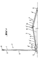
- Fig. 1 shows an embodiment of an overall system according to the invention from the side
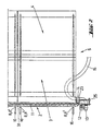
- Fig. 2 is the associated top view
- Fig. 3 is a section along the line B-B in Fig. 4
- Fig. 4 is a section along the line A-A in Fig. 3, each through the enlarged inlet housing for the balls.
- the arrangement according to the invention essentially consists of an at least approximately vertical baffle wall 2 carried by stands 16, which, like the ramp 5 composed of an ascending area 3 and a descending area 4, is provided with a covering 1.
- This covering runs between edge strips 6 and 6 ', which are telescopic nested side parts 8, 8 'are kept at a distance.
- a joint 10 holds the ramp 5 in the position shown, so that a collecting channel is formed between the ramp 5 and the baffle wall 2.
- the tennis balls 17 in the present exemplary embodiment are conveyed by a screw conveyor 11 to an inlet housing 23, into which they are individually introduced by a paddle wheel 14.
- This paddle wheel 14 is driven by means of a transmission gear 25 from the same motor 12 as the screw conveyor 11. From the housing 23, the tennis balls 17 are pressed by the air flow coming from a blower 13 into the hose 15, through which they reach the collecting container, not shown, for example a ball throwing machine.
- baffle 2 and ramp 5 are composed of individual parts of constant width, which makes the entire system easy to transport and can also be assembled in different widths from prepared elements.
- a single conveyor is sufficient to transport the tennis balls 17.
- the screw conveyor 11 is to be provided with pluggable ends 31 which allow it to be attached to any length.
- a conveyor screw 11 consisting of a rod 18 and a helix 19 placed around it conveys balls 17 to the end of the collecting trough, where they are fed to the paddle wheel 14 by a deflection plate 32.
- This paddle wheel 14 moves in the inlet housing 23 for the balls 17, which is traversed by an air stream 28, which can be generated by a conventional fan.
- the paddle wheel 14 rotates in the direction of the arrow 29 and, in an orderly sequence, brings the balls 17 into the air stream 28, which sweeps them along and moves them to the ball throwing machine through the hose 15, not shown in FIG.
- a particular advantage of the arrangement shown is that two blades of the impeller 14 close the entrance of the housing and thereby prevent air from escaping from the housing 23.
- the balls 17 can thus reach the detection area of the paddle wheel without having to overcome the resistance of the outflowing air.
- the arrangement can be made very compact in that a single motor drives the screw conveyor 11 and - via the shaft 27 - the paddle wheel 14.
- a suitable choice of the transmission ratio of the transmission 25 it can be ensured that, in the normal case, the balls reach the inlet housing 23 at intervals in which there are no jams at the entrance to the housing. If, moreover, as shown in FIG. 2, the motor 12 is in the inlet area of the blower 13, the air sucked in by the blower 13 brings about additional motor cooling.
Landscapes
- Engineering & Computer Science (AREA)
- Mechanical Engineering (AREA)
- Physics & Mathematics (AREA)
- Physical Education & Sports Medicine (AREA)
- Fluid Mechanics (AREA)
- General Health & Medical Sciences (AREA)
- Health & Medical Sciences (AREA)
- Breeding Of Plants And Reproduction By Means Of Culturing (AREA)
- Closures For Containers (AREA)
- Agricultural Chemicals And Associated Chemicals (AREA)
- Handcart (AREA)
- Filling Or Emptying Of Bunkers, Hoppers, And Tanks (AREA)
- Feeding Of Articles To Conveyors (AREA)
- Refuse Collection And Transfer (AREA)
- Acyclic And Carbocyclic Compounds In Medicinal Compositions (AREA)
- Pallets (AREA)
- Structures Of Non-Positive Displacement Pumps (AREA)
- Pinball Game Machines (AREA)
- Holding Or Fastening Of Disk On Rotational Shaft (AREA)
- Screw Conveyors (AREA)
- Medicines Containing Plant Substances (AREA)
Applications Claiming Priority (2)
| Application Number | Priority Date | Filing Date | Title |
|---|---|---|---|
| AT61183 | 1983-02-23 | ||
| AT611/83 | 1983-02-23 |
Publications (2)
| Publication Number | Publication Date |
|---|---|
| EP0135527A1 EP0135527A1 (de) | 1985-04-03 |
| EP0135527B1 true EP0135527B1 (de) | 1986-12-10 |
Family
ID=3495177
Family Applications (1)
| Application Number | Title | Priority Date | Filing Date |
|---|---|---|---|
| EP84900703A Expired EP0135527B1 (de) | 1983-02-23 | 1984-02-16 | Anlage zum fördern von tennisbällen |
Country Status (12)
| Country | Link |
|---|---|
| EP (1) | EP0135527B1 (Direct) |
| JP (1) | JPS60500600A (Direct) |
| AT (1) | ATE24115T1 (Direct) |
| AU (1) | AU571199B2 (Direct) |
| CA (1) | CA1223019A (Direct) |
| DE (1) | DE3461597D1 (Direct) |
| DK (1) | DK154611C (Direct) |
| FI (1) | FI77378C (Direct) |
| IT (1) | IT1173321B (Direct) |
| NZ (1) | NZ207236A (Direct) |
| WO (1) | WO1984003223A1 (Direct) |
| ZA (1) | ZA841246B (Direct) |
Cited By (1)
| Publication number | Priority date | Publication date | Assignee | Title |
|---|---|---|---|---|
| KR101835068B1 (ko) * | 2016-12-01 | 2018-03-07 | 주식회사 골프존 | 볼 이송장치 |
Families Citing this family (1)
| Publication number | Priority date | Publication date | Assignee | Title |
|---|---|---|---|---|
| DE10127232B4 (de) * | 2001-05-28 | 2006-01-19 | Hüttlin, Herbert, Dr. h.c. | Vorrichtung zum Behandeln eines partikelförmigen Guts mit einem Überzugsmedium |
Family Cites Families (3)
| Publication number | Priority date | Publication date | Assignee | Title |
|---|---|---|---|---|
| US3989246A (en) * | 1973-12-14 | 1976-11-02 | Brown Alvin I | Tennis practice system |
| JPS5399191A (en) * | 1977-02-08 | 1978-08-30 | Toshiba Corp | Plenum device |
| DE2720593A1 (de) * | 1977-05-07 | 1978-11-09 | Adolf Lesk | Schleusse fuer schuettgueter mit geringer einbauhoehe |
-
1984
- 1984-02-16 EP EP84900703A patent/EP0135527B1/de not_active Expired
- 1984-02-16 DE DE8484900703T patent/DE3461597D1/de not_active Expired
- 1984-02-16 WO PCT/AT1984/000007 patent/WO1984003223A1/de not_active Ceased
- 1984-02-16 AU AU24985/84A patent/AU571199B2/en not_active Ceased
- 1984-02-16 JP JP59500850A patent/JPS60500600A/ja active Granted
- 1984-02-16 AT AT84900703T patent/ATE24115T1/de not_active IP Right Cessation
- 1984-02-21 ZA ZA841246A patent/ZA841246B/xx unknown
- 1984-02-21 IT IT19717/84A patent/IT1173321B/it active
- 1984-02-22 CA CA000448017A patent/CA1223019A/en not_active Expired
- 1984-02-22 NZ NZ207236A patent/NZ207236A/en unknown
- 1984-10-16 FI FI844075A patent/FI77378C/fi not_active IP Right Cessation
- 1984-10-22 DK DK503184A patent/DK154611C/da not_active IP Right Cessation
Cited By (1)
| Publication number | Priority date | Publication date | Assignee | Title |
|---|---|---|---|---|
| KR101835068B1 (ko) * | 2016-12-01 | 2018-03-07 | 주식회사 골프존 | 볼 이송장치 |
Also Published As
| Publication number | Publication date |
|---|---|
| DE3461597D1 (en) | 1987-01-22 |
| DK154611C (da) | 1989-05-16 |
| FI844075A0 (fi) | 1984-10-16 |
| IT1173321B (it) | 1987-06-24 |
| CA1223019A (en) | 1987-06-16 |
| WO1984003223A1 (fr) | 1984-08-30 |
| JPH0454469B2 (Direct) | 1992-08-31 |
| JPS60500600A (ja) | 1985-05-02 |
| IT8419717A0 (it) | 1984-02-21 |
| DK503184D0 (da) | 1984-10-22 |
| FI77378C (fi) | 1989-03-10 |
| ZA841246B (en) | 1984-10-31 |
| FI77378B (fi) | 1988-11-30 |
| FI844075L (fi) | 1984-10-16 |
| AU571199B2 (en) | 1988-04-14 |
| DK503184A (da) | 1984-10-22 |
| DK154611B (da) | 1988-12-05 |
| ATE24115T1 (de) | 1986-12-15 |
| NZ207236A (en) | 1986-02-21 |
| AU2498584A (en) | 1984-09-10 |
| EP0135527A1 (de) | 1985-04-03 |
Similar Documents
| Publication | Publication Date | Title |
|---|---|---|
| DE1816221C3 (de) | Vorrichtung zum Fördern von durch Wasser überdeckten Ablagerungen, insbesondere von Kies od.dgl | |
| DE2760290C2 (Direct) | ||
| DE102013215182A1 (de) | Verfahren zur Dosierung von körnigem Gut und Dosiervorrichtung für körniges Gut | |
| DE2657565A1 (de) | Reinigungs- und entstaubungsmaschine | |
| EP0135527B1 (de) | Anlage zum fördern von tennisbällen | |
| CH665196A5 (de) | Foerdergeblaese fuer textiles fasergut. | |
| DE2830444C3 (de) | Förder- und Verteileinrichtung zum Befüllen von Hochsilos | |
| DE8490033U1 (de) | Vorrichtung zum Fördern von Tennisbällen | |
| EP0136295B1 (de) | Anlage zum Fördern von Tennisbällen | |
| DE1404880A1 (de) | Vorrichtung zum Reinigen von Textilmaschinen od.dgl. durch Luftstroeme | |
| DE2419471A1 (de) | Sieb, insbesondere fuer ein schlachthaus | |
| DE279671C (Direct) | ||
| DE3408271A1 (de) | Vorrichtung zum pneumatischen, lotrechten foerdern von foerdergut, wie getreide | |
| DE2306732C3 (de) | Axialventilator mit einer Zerstäubungsvorrichtung für Flüssigkeiten Bosch-Siemens Hausgeräte GmbH, 7000 Stuttgart | |
| DE102019105274A1 (de) | Trennvorrichtung | |
| DE949998C (de) | Vorrichtung zum Einschleusen, Dosieren oder Saugdruckfoerdern von staubfoermigen oder griessigen Massenguetern | |
| AT85554B (de) | Einrichtung bei Saugluftförderanlagen für sinterndes oder backendes Fördergut. | |
| DE102023132338A1 (de) | Packanlage und Verfahren zum Betreiben | |
| DE1756648C3 (de) | Fahrbare pneumatische Fördervorrichtung für Schüttgut aller Art | |
| DE10162598A1 (de) | Vorrichtung zum Transport von kleinstückigen Gegenständen | |
| DE1923413C3 (de) | Luftfördergerät für großvolumiges, leichtes Fördergut | |
| AT158157B (de) | Förderanlage zum Aufnehmen von Schüttgut mit Zuführungstellern. | |
| DE8314639U1 (de) | Vorrichtung zum pneumatischen, lotrechten foerdern von foerdergut, wie getreide | |
| DE2649379C2 (de) | Pneumatische Fördereinrichtung zum Verteilen von Rauhfutter | |
| DE2653699A1 (de) | Pneumatische saug-druck-foerderung von silagegut |
Legal Events
| Date | Code | Title | Description |
|---|---|---|---|
| PUAI | Public reference made under article 153(3) epc to a published international application that has entered the european phase |
Free format text: ORIGINAL CODE: 0009012 |
|
| 17P | Request for examination filed |
Effective date: 19841003 |
|
| AK | Designated contracting states |
Designated state(s): AT BE CH DE FR GB LI NL SE |
|
| 17Q | First examination report despatched |
Effective date: 19860130 |
|
| GRAA | (expected) grant |
Free format text: ORIGINAL CODE: 0009210 |
|
| AK | Designated contracting states |
Kind code of ref document: B1 Designated state(s): AT BE CH DE FR GB LI NL SE |
|
| REF | Corresponds to: |
Ref document number: 24115 Country of ref document: AT Date of ref document: 19861215 Kind code of ref document: T |
|
| REF | Corresponds to: |
Ref document number: 3461597 Country of ref document: DE Date of ref document: 19870122 |
|
| ET | Fr: translation filed | ||
| PLBE | No opposition filed within time limit |
Free format text: ORIGINAL CODE: 0009261 |
|
| STAA | Information on the status of an ep patent application or granted ep patent |
Free format text: STATUS: NO OPPOSITION FILED WITHIN TIME LIMIT |
|
| 26N | No opposition filed | ||
| PGFP | Annual fee paid to national office [announced via postgrant information from national office to epo] |
Ref country code: SE Payment date: 19920224 Year of fee payment: 9 |
|
| PGFP | Annual fee paid to national office [announced via postgrant information from national office to epo] |
Ref country code: BE Payment date: 19920226 Year of fee payment: 9 |
|
| PGFP | Annual fee paid to national office [announced via postgrant information from national office to epo] |
Ref country code: NL Payment date: 19920229 Year of fee payment: 9 |
|
| PG25 | Lapsed in a contracting state [announced via postgrant information from national office to epo] |
Ref country code: SE Effective date: 19930217 |
|
| PG25 | Lapsed in a contracting state [announced via postgrant information from national office to epo] |
Ref country code: BE Effective date: 19930228 |
|
| BERE | Be: lapsed |
Owner name: STABEG APPARATEBAUG- M.B.H. Effective date: 19930228 |
|
| PG25 | Lapsed in a contracting state [announced via postgrant information from national office to epo] |
Ref country code: NL Effective date: 19930901 |
|
| NLV4 | Nl: lapsed or anulled due to non-payment of the annual fee | ||
| PGFP | Annual fee paid to national office [announced via postgrant information from national office to epo] |
Ref country code: CH Payment date: 19940124 Year of fee payment: 11 |
|
| PGFP | Annual fee paid to national office [announced via postgrant information from national office to epo] |
Ref country code: GB Payment date: 19940215 Year of fee payment: 11 |
|
| PGFP | Annual fee paid to national office [announced via postgrant information from national office to epo] |
Ref country code: FR Payment date: 19940224 Year of fee payment: 11 |
|
| EUG | Se: european patent has lapsed |
Ref document number: 84900703.4 Effective date: 19930912 |
|
| PG25 | Lapsed in a contracting state [announced via postgrant information from national office to epo] |
Ref country code: GB Effective date: 19950216 |
|
| PG25 | Lapsed in a contracting state [announced via postgrant information from national office to epo] |
Ref country code: LI Effective date: 19950228 Ref country code: CH Effective date: 19950228 |
|
| GBPC | Gb: european patent ceased through non-payment of renewal fee |
Effective date: 19950216 |
|
| PG25 | Lapsed in a contracting state [announced via postgrant information from national office to epo] |
Ref country code: FR Effective date: 19951031 |
|
| REG | Reference to a national code |
Ref country code: FR Ref legal event code: ST |
|
| PGFP | Annual fee paid to national office [announced via postgrant information from national office to epo] |
Ref country code: AT Payment date: 19960214 Year of fee payment: 13 |
|
| PGFP | Annual fee paid to national office [announced via postgrant information from national office to epo] |
Ref country code: DE Payment date: 19960426 Year of fee payment: 13 |
|
| PG25 | Lapsed in a contracting state [announced via postgrant information from national office to epo] |
Ref country code: AT Effective date: 19970216 |
|
| PG25 | Lapsed in a contracting state [announced via postgrant information from national office to epo] |
Ref country code: DE Effective date: 19971101 |