EP0135149B1 - Rafflamellenjalousie mit Z-förmig profilierten Lamellen - Google Patents
Rafflamellenjalousie mit Z-förmig profilierten Lamellen Download PDFInfo
- Publication number
- EP0135149B1 EP0135149B1 EP84109729A EP84109729A EP0135149B1 EP 0135149 B1 EP0135149 B1 EP 0135149B1 EP 84109729 A EP84109729 A EP 84109729A EP 84109729 A EP84109729 A EP 84109729A EP 0135149 B1 EP0135149 B1 EP 0135149B1
- Authority
- EP
- European Patent Office
- Prior art keywords
- slats
- slat
- nesting
- middle portion
- shutter
- Prior art date
- Legal status (The legal status is an assumption and is not a legal conclusion. Google has not performed a legal analysis and makes no representation as to the accuracy of the status listed.)
- Expired
Links
- 230000000295 complement effect Effects 0.000 claims abstract description 6
- 238000007789 sealing Methods 0.000 claims description 8
- 210000002445 nipple Anatomy 0.000 claims description 7
- 239000000463 material Substances 0.000 claims description 4
- 229910052751 metal Inorganic materials 0.000 claims description 2
- 239000002184 metal Substances 0.000 claims description 2
- 241000446313 Lamella Species 0.000 description 11
- 229910052782 aluminium Inorganic materials 0.000 description 1
- XAGFODPZIPBFFR-UHFFFAOYSA-N aluminium Chemical compound [Al] XAGFODPZIPBFFR-UHFFFAOYSA-N 0.000 description 1
- 230000015572 biosynthetic process Effects 0.000 description 1
- 239000004020 conductor Substances 0.000 description 1
- 238000011161 development Methods 0.000 description 1
- 230000018109 developmental process Effects 0.000 description 1
- 238000006073 displacement reaction Methods 0.000 description 1
- 230000000694 effects Effects 0.000 description 1
- 230000012447 hatching Effects 0.000 description 1
- 238000009413 insulation Methods 0.000 description 1
Images

Classifications
-
- E—FIXED CONSTRUCTIONS
- E06—DOORS, WINDOWS, SHUTTERS, OR ROLLER BLINDS IN GENERAL; LADDERS
- E06B—FIXED OR MOVABLE CLOSURES FOR OPENINGS IN BUILDINGS, VEHICLES, FENCES OR LIKE ENCLOSURES IN GENERAL, e.g. DOORS, WINDOWS, BLINDS, GATES
- E06B9/00—Screening or protective devices for wall or similar openings, with or without operating or securing mechanisms; Closures of similar construction
- E06B9/24—Screens or other constructions affording protection against light, especially against sunshine; Similar screens for privacy or appearance; Slat blinds
- E06B9/26—Lamellar or like blinds, e.g. venetian blinds
- E06B9/28—Lamellar or like blinds, e.g. venetian blinds with horizontal lamellae, e.g. non-liftable
- E06B9/30—Lamellar or like blinds, e.g. venetian blinds with horizontal lamellae, e.g. non-liftable liftable
-
- E—FIXED CONSTRUCTIONS
- E06—DOORS, WINDOWS, SHUTTERS, OR ROLLER BLINDS IN GENERAL; LADDERS
- E06B—FIXED OR MOVABLE CLOSURES FOR OPENINGS IN BUILDINGS, VEHICLES, FENCES OR LIKE ENCLOSURES IN GENERAL, e.g. DOORS, WINDOWS, BLINDS, GATES
- E06B9/00—Screening or protective devices for wall or similar openings, with or without operating or securing mechanisms; Closures of similar construction
- E06B9/24—Screens or other constructions affording protection against light, especially against sunshine; Similar screens for privacy or appearance; Slat blinds
- E06B9/26—Lamellar or like blinds, e.g. venetian blinds
- E06B9/38—Other details
- E06B9/386—Details of lamellae
Definitions
- the invention relates to a Roman blind with a curtain made of essentially Z-shaped slats with a central section and two complementary, equally wide side sections adjoining on both sides at obtuse to right angles, supporting elements for carrying and turning as well as elevator elements for gathering or lowering the Serve slats.
- the Z-shape of the slats in the new RaffIameIlen blinds has a completely different cause and meaning.
- the purpose of this new Roman blind is to provide a particularly compact and, in particular, heat-insulating slatted curtain when closed.
- the width of the slat side sections is substantially equal to the distance between the slats (pitch) and in the fully turned condition each side section of a slat with its adjacent central section and the complementary side section and adjacent middle section of an adjacent lamella forms an essentially closed hollow profile and adjacent hollow profiles are vertically aligned with one another.
- the slat width is only slightly larger than the pitch
- the new Roman blind has slats, the total width of which essentially corresponds to twice the pitch, so that when fully turned, i.e. closed, each slat covers half of its two neighboring slats.
- the good thermal insulation caused by the air cushions in the hollow profiles of the closed Roman blinds can be further improved if the slats are divided in the area of the central section and the parts are connected to one another by a poorly heat-conducting bridge.
- This measure will be used primarily with fins made of metal, in particular aluminum, which combine good mechanical properties with good thermal conductivity and thus favor the heat transfer.
- the heat conduction is interrupted in the area of the central sections, this disadvantageous aspect can be effectively countered.
- Such slats divided in the area of the central section can be made from differently machined parts and / or from different materials. In this way, a variety of light-influencing effects can be achieved, both in the open and in the turned (closed) state of the blind.
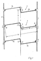
- FIGS. 1 and 2 represent a simple embodiment of only a section of the slatted curtain of an otherwise generally known roman blind slat.
- the slats designated 1 as a whole each consist of a central section 2 and side sections 3a and 3b on both sides.
- the slats 1 are guided vertically in the side guide rails, not shown, with the aid of schematically indicated nipples 4, which are fastened to the central sections 2.
- the lamellae 1 are articulated on the supporting and turning elements 5 with the aid of connecting pieces 6.
- the center distance between adjacent nipples 4 defines the pitch of the blind curtain; in the example it is labeled x.
- B denotes the total width of a lamella 1
- b denotes the effective width of a side section 3a or 3b. If the angle between the middle section 2 and the adjacent side sections 3a, 3b deviates from 90 ° (obtuse angle), part of the middle section 2 is included in the effective width of the side section 3a or 3b.
- the effective width b of the side sections 3a, 3b is equal to the pitch x is such that a lamella of the total width B covers the side section 3a of the lamella 1 adjacent to it on one side and the side section 3b of the lamella 1 adjacent to it on the other side, and with these side sections and the involved middle sections 2 involved two hollow profiles 7 forms.
- the flanged edges 8 lie along the free edges of the lamella side sections 3a, 3b on the middle sections 2 involved.
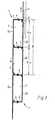
- the side sections 3a, 3b form obtuse angles with the central section 2. They can be pivoted about the axis 9 of the nipple 4, which is guided in the side rail 10 and in this example has a crank shoulder 11 (FIG. 4).
- the support and turning elements 5 are arranged at the ends of the slats 1. Only the support and turning element 5 on the right in the drawing attacks with the aid of its connecting pieces 6 on the free edge of the associated side section 3b. The other - left - support and turning element 5 does not engage directly on the lamellae 1, but (with the aid of similar connecting pieces 6) on the free ends of the nipple cranks 11 with the aid of pins 12 fastened thereon. Corresponding pins 13 are also provided for the articulation of the (right) support and turning element 5 in the region of the free edges of the side sections 3b at the end of the lamellae 1 (FIG. 4).
- FIG. 3 and 4 show with solid lines the closed state of the Venetian blind, in which the slats 1 in turn form hollow profiles 7.
- the slats 1 reach this position when the support and turning elements 5 are moved relative to one another according to the arrows 14.
- An oppositely directed relative movement of the supporting and turning elements 5 allows the slats 1 to pivot into the open position indicated by dash-dotted lines; each connector 6 attached to the right-hand support and turning element 5 in the drawing figures moves on a quarter circle 15, which is likewise indicated by dash-dotted lines for the lamella 1 shown in dash-dotted lines in FIG.
- the associated support and turning member 5 moves parallel to its position shown to the right (not shown); the other (left) support and turning element 5 experiences a corresponding parallel displacement due to the associated pivoting of all cranks 11.
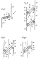
- FIG. 5 shows a partial cross section of the structure of a longitudinally divided lamella 1.
- the side sections 3a and 3b consist of different material, as the different hatching shows. This material can be a plastic, for example, and the differences can be limited to different processing (e.g. prism formation in clear plastic, with certain prism edges being coated for light control).
- the side section 3a continues in a middle leg section 2a and the side section 3b continues in a middle leg section 2b.
- a support or connecting bar 2c is provided, which is glued to the sections 2a, 2b along the connecting surfaces 2d, for example, and in this way forms the overall central section 2 of the lamella 1.
- FIG. 6 shows a different slat design, also in the vertical section of adjacent slats in the closed position.
- the middle section 2 essentially consists of a compact bar 2c, in which correspondingly shorter middle bar sections 2a, 2b of the side sections 3a, 3b engage in alignment; the cranking angle between the side sections 3a, 3b and the middle bar sections 2a, 2b also deviates from 90 ° in this case.
- the strip 2c (as in the example in FIG. 5) can consist of particularly poorly heat-conducting material.
- Sealing strips 17 (made of rubber, plastic or the like) are inserted into appropriately shaped edge flanges 16 of the side sections 3a, 3b with the aid of thickened edges 18.
- the lips 19 of the sealing strips 17 rest against the strip 2c of the central section 2 of the respective neighboring slat 1, so that the cavity 7 is effectively sealed.
- sealing strips 20 are part of the strip 2c, which also makes up the largest part of the central section 2 here.
- the sealing strips 20 are stretched.
- the flanges 16 of the two adjacent slats 1 come to rest against the bar 20 ( Figure 7).
- the sealing strips 20 are deformed in sealing contact with the flanges 16 (FIG. 8).
Landscapes
- Engineering & Computer Science (AREA)
- Structural Engineering (AREA)
- Architecture (AREA)
- Civil Engineering (AREA)
- Blinds (AREA)
- Non-Silver Salt Photosensitive Materials And Non-Silver Salt Photography (AREA)
- Special Spraying Apparatus (AREA)
- Devices For Indicating Variable Information By Combining Individual Elements (AREA)
- Specific Sealing Or Ventilating Devices For Doors And Windows (AREA)
Description
- Die Erfindung betrifft eine Rafflamellenjalousie mit einem Behang aus im wesentlichen Z-förmig profilierten Lamellen mit einem Mittelabschnitt und zwei komplementären, sich beidseits unter stumpfen bis rechten Winkeln anschließenden, gleich breiten Seitenabschnitten, wobei Tragorgane zum Tragen und Wenden sowie Aufzugsorgane zum Raffen bzw. Herablassen der Lamellen dienen.
- Derartige Rafflamellenjalousien mit Z-förmigen Lamellen sind vielfältig bekannt. Die Neigung des Mittelabschnitts gegenüber den beiden Seitenabschnitten hat dabei den Vorteil, daß die Öffnungen für das alle Mittelabschnitte der Lamellen durchsetzende Aufzugsorgan trotz eines großen Wendewinkels der Lamellen relativ klein sein können.
- Die Z-Form der Lamellen der neuen RaffIameIlenjalousie hat demgegenüber eine gänzlich andere Ursache und Bedeutung. Dieser neuen Rafflamellenjalousie liegt die Aufgabe zugrunde, einen im geschlossenen Zustand besonders kompakten und insbesondere wärmedämmenden Lamellenbehang anzugeben.
- Diese Aufgabe wird erfindungsgemäß - mit Hilfe an sich bekannter Z-Lamellen - dadurch gelöst, daß die Breite der Lamellen-Seitenabschnitte im wesentlichen gleich dem Abstand der Lamellen (Teilungsmaß) ist und im voll gewendeten Zustand jeder Seitenabschnitt einer Lamelle mit deren angrenzendem Mittelabschnitt sowie dem komplementären Seitenabschnitt nebst angrenzendem Mittelabschnitt einer benachbarten Lamelle ein im wesentlichen geschlossenes Hohlprofil bildet sowie benachbarte Hohlprofile vertikal miteinander fluchten. Während bei herkömmlichen Rafflamellenjalousien die Lamellenbreite nur wenig größer als das Teilungsmaß ist, hat die neue Rafflamellenjalousie Lamellen, deren Gesamtbreite im wesentlichen dem doppelten Teilungsmaß entspricht, so daß im voll gewendeten, also geschlossenen Zustand jede Lamelle ihre beiden Nachbarlamellen je zur Hälfte überdeckt.
- Die von den Luftpolstern in den Hohlprofilen der geschlossenen Rafflamellenjalousie bewirkte gute Wärmedämmung läßt sich weiter verbessern, wenn die Lamellen im Bereich des Mitteiabschnitts geteilt und die Teile durch eine schlecht wärmeleitende Brücke miteinander verbunden sind. Diese Maßnahme wird vornehmlich bei Lamellen aus Metall, insbesondere Aluminium, Anwendung finden, die gute mechanische Eigenschaften mit guter Wärmeleitfähigkeit verbinden und insofern den Wärmedurchgang begünstigen. Wird die Wärmeleitung im Bereich der Mittelabschnitte jedoch unterbrochen, so kann diesem nachteiligen Aspekt wirksam begegnet werden.
- Vornehmlich solche im Bereich des Mittelabschnitts geteilte Lamellen können aus unterschiedlich bearbeiteten und/oder aus unterschiedlichen Werkstoffen bestehenden Teilen hergestellt sein. Es lassen sich auf diese Weise eine Vielzahl von lichtbeeinflussenden Wirkungen erzielen, und zwar sowohl im geöffneten als auch im gewendeten (geschlossenen) Zustand der Jalousie.
- Andere vorteilhafte Weiterbildungen und Ausgestaltungen der neuen Raftlamellenjalousie ergeben sich aus der nachfolgenden Beschreibung von Ausführungsbeispielen und sind Gegenstand von Unteransprüchen.
- In den Zeichnungen zeigt
- Fig. 1 in schematischer Darstellung eine einfache Ausbildung der neuen Rafflamellenjalousie, und zwar im geöffneten Zustand ;
- Fig. 2 dieselbe Jalousie im geschlossenen Zustand (wie Fig. 1 im Vertikalschnitt) ;
- Fig. 3 eine insbesondere der Fig. 2 entsprechende Darstellung einer abgewandelten Ausführungsform ;
- Fig. 4 eine teilweise horizontal geschnittene Draufsicht auf die in Fig. 3 dargestellte Ausführungsform ;
- Fig. 5 den Mittelabschnitt nebst angrenzenden Teilen der Seitenabschnitte einer geteilten Lamelle im Vertikalschnitt ;
- Fig. 6 eine den Fig. 2 und 3 entsprechende Darstellung einer anderen Ausführungsform mit geteilten Lamellen (im geschlossenen Zustand der Jalousie) ;
- Fig. 7 einen partiellen Ausschnitt der Darstellung in Fig. 6, jedoch einer wiederum abgewandelten Ausführungsform im fast geschlossenen Zustand ; und
- Fig. 8 eine der Fig. 7 entsprechende Darstellung derselben Ausführungsform im gänzlich geschlossenen Zustand.
- Die Figuren 1 und 2 stellen - wie gesagt - eine einfache Ausführungsform nur eines Ausschnitts des Lamellenbehangs einer im übrigen allgemein bekannten Rafflamellenjalousie dar. Die im ganzen mit 1 bezeichneten Lamellen bestehen jeweils aus einem Mittelabschnitt 2 und beidseitigen Seitenabschnitten 3a und 3b. Die Lamellen 1 sind mit Hilfe von schematisch angedeuteten Nippeln 4, welche an den Mittelabschnitten 2 befestigt sind, in nicht dargestellten Seitenführungsschienen vertikal geführt. Im Bereich der freien Ränder der Seitenabschnitte 3a, 3b sind die Lamellen 1 an Trag- und Wendeorganen 5 mit Hilfe von Verbindungsstücken 6 angelenkt.
- Der Mittenabstand benachbarter Nippel 4 (bzw. benachbarter Verbindungsstücke 6) definiert das Teilungsmaß des Jalousiebehangs ; es ist im Beispiel mit x bezeichnet. Mit B ist die Gesamtbreite einer Lamelle 1 bezeichnet, mit b die wirksame Breite eines Seitenabschnitts 3a bzw. 3b. Weicht der Winkel zwischen dem Mittelabschnitt 2 und den angrenzenden Seitenabschnitten 3a, 3b von 90° ab (stumpfer Winkel), so geht ein Teil des Mittelabschnitts 2 in die wirksame Breite des Seitenabschnitts 3a bzw. 3b ein. Vor allem Fig. 2 macht deutlich, daß die wirksame Breite b der Seitenabschnitte 3a, 3b gleich dem Teilungsmaß x ist, so daß eine Lamelle von der Gesamtbreite B den Seitenabschnitt 3a der ihr auf einer Seite benachbarten Lamelle 1 und den Seitenabschnitt 3b der ihr auf der anderen Seite benachbarten Lamelle 1 überdeckt und mit diesen Seitenabschnitten sowie den beteiligten, jeweils dazwischenliegenden Mittelabschnitten 2 zwei Hohlprofile 7 bildet. Dabei liegen die Bördelränder 8 entlang den freien Kanten der Lamellen-Seitenabschnitte 3a, 3b an den beteiligten Mittelabschnitten 2 an.
- Beim Ausführungsbeispiel der Figuren 3 und 4 schließen die Seitenabschnitte 3a, 3b stumpfe Winkel mit dem Mittelabschnitt 2 ein. Sie sind um die Achse 9 des Nippels 4 schwenkbar, welcher in der Seitenschiene 10 geführt ist und in diesem Beispiel einen Kurbelansatz 11 besitzt (Fig. 4).
- Die Trag- und Wendeorgane 5 sind endseits der Lamellen 1 angeordnet. Dabei greift nur das in der Zeichnung rechte Trag- und Wendeorgan 5 mit Hilfe seiner Verbindungsstücke 6 am freien Rand des zugehörigen Seitenabschnitts 3b an. Das andere - linke - Trag- und Wendeorgan 5 greift gar nicht unmittelbar an den Lamellen 1, sondern (mit Hilfe gleichartiger Verbindungsstücke 6) an den freien Enden der Nippel-Kurbeln 11 mit Hilfe daran befestigter Zapfen 12 an. Entsprechende Zapfen 13 sind übrigens zur Anlenkung des (rechten) Trag- und Wendeorgans 5 im Bereich der freien Ränder der Seitenabschnitte 3b endseits der Lamellen 1 auch vorgesehen (Fig. 4).
- Die Fig. 3 und 4 stellen mit ausgezogenen Linien den geschlossenen Zustand der RaffIameIlenjalousie dar, in welchem die Lamellen 1 wiederum Hohlprofile 7 bilden. In diese Stellung gelangen die Lamellen 1, wenn die Trag- und Wendeorgane 5 gemäß den Pfeilen 14 relativ zueinander bewegt werden. Eine entgegengesetzt gerichtete Relativbewegung der Trag- und Wendeorgane 5 läßt die Lamellen 1 in die strich-punktiert angedeutete Offenlage schwenken ; dabei bewegt sich jedes an dem in den Zeichnungsfiguren rechten Trag- und Wendeorgan 5 angebrachtes Verbindungsstück 6 auf einem Viertelkreis 15, welcher für die strich-punktiert dargestellte Lamelle 1 in Figur 3 ebenfalls strich-punktiert angegeben ist. Das zugehörige Trag- und Wendeorgan 5 verlagert sich parallel zu seiner dargestellten Stellung nach rechts (nicht dargestellt) ; eine entsprechende Parallelverlagerung erfährt das andere (linke) Trag- und Wendeorgan 5 aufgrund der damit einhergehenden Schwenkung aller Kurbeln 11.
- Figur 5 zeigt im Teilquerschnitt den Aufbau einer längsgeteilten Lamelle 1. Die Seitenabschnitte 3a und 3b bestehen dabei aus unterschiedlichem Material, wie die verschiedene Schraffierung deutlich macht. Dieses Material kann beispielsweise ein Kunststoff sein, und die Unterschiede können sich auf unterschiedliche Bearbeitung (z. B. Prismenausbildung in glasklarem Kunststoff, wobei bestimmte Prismenkanten zur Lichtlenkung beschichtet sein können) beschränken. Der Seitenabschnitt 3a setzt sich in einem Mittelschenkel-Abschnitt 2a und der Seitenabschnitt 3b in einem Mittelschenkel-Abschnitt 2b fort. Zwischen den Abschnitten 2a, 2b ist eine Trag- oder Verbindungsleiste 2c vorgesehen, welche entlang den Verbindungsflächen 2d mit den Abschnitten 2a, 2b beispielsweise verklebt ist und auf diese Weise insgesamt den Mittelabschnitt 2 der Lamelle 1 bildet.
- Figur 6 zeigt eine wieder andere Lamellenausbildung, und zwar auch im vertikalen Ausschnitt benachbarter Lamellen in der Schließstellung. Hier besteht der Mittelabschnitt 2 im wesentlichen aus einer kompakten Leiste 2c, in die entsprechend kürzere Mittelleisten-Abschnitte 2a, 2b der Seitenabschnitte 3a, 3b fluchtend eingreifen ; der Abkröpfwinkel zwischen den Seitenabschnitten 3a, 3b und den Mittelleisten-Abschnitten 2a, 2b weicht auch in diesem Falle von 90° ab. Die Leiste 2c kann (ebenso wie im Beispiel der Figur 5) aus besonders schlecht wärmeleitendem Material bestehen.
- In entsprechend geformte Randbördelungen 16 der Seitenabschnitte 3a, 3b sind Dichtleisten 17 (aus Gummi, Kunststoff o. dgl.) mit Hilfe verdickter Ränder 18 eingeführt. In dem in Figur 6 dargestellten geschlossenen Zustand der Jalousie liegen die Lippen 19 der Dichtleisten 17 an der Leiste 2c des Mittelabschnitts 2 der jeweiligen Nachbarlamelle 1 an, so daß der Hohlraum 7 wirksam abgedichtet ist.
- Gemäß dem in den Figuren 7 und 8 dargestellten Ausführungsbeispiel sind Dichtleisten 20 Teil der Leiste 2c, welche auch hier den größten Teil des Mittelabschnitts 2 ausmacht. Im geöffneten Zustand der Lamellen 1 sind die Dichtleisten 20 gestreckt. Beim Schließen kommen die Bördelungen 16 der jeweils beiden benachbarten Lamellen 1 zur Anlage an die Leiste 20 (Figur 7). Wenn die Rafflamellenjalousie völlig geschlossen ist und jeweils benachbarte Lamellen 1 Hohlräume 7 gebildet haben, sind die Dichtleisten 20 in dichtende Anlage an den Bördelungen 16 verformt (Figur 8).
Claims (9)
Priority Applications (1)
| Application Number | Priority Date | Filing Date | Title |
|---|---|---|---|
| AT84109729T ATE33168T1 (de) | 1983-08-20 | 1984-08-16 | Rafflamellenjalousie mit z-foermig profilierten lamellen. |
Applications Claiming Priority (2)
| Application Number | Priority Date | Filing Date | Title |
|---|---|---|---|
| DE3330106A DE3330106A1 (de) | 1983-08-20 | 1983-08-20 | Rafflamellenjalousie mit z-foermig profilierten lamellen |
| DE3330106 | 1983-08-20 |
Publications (3)
| Publication Number | Publication Date |
|---|---|
| EP0135149A2 EP0135149A2 (de) | 1985-03-27 |
| EP0135149A3 EP0135149A3 (en) | 1985-10-30 |
| EP0135149B1 true EP0135149B1 (de) | 1988-03-23 |
Family
ID=6207033
Family Applications (1)
| Application Number | Title | Priority Date | Filing Date |
|---|---|---|---|
| EP84109729A Expired EP0135149B1 (de) | 1983-08-20 | 1984-08-16 | Rafflamellenjalousie mit Z-förmig profilierten Lamellen |
Country Status (3)
| Country | Link |
|---|---|
| EP (1) | EP0135149B1 (de) |
| AT (1) | ATE33168T1 (de) |
| DE (2) | DE3330106A1 (de) |
Family Cites Families (4)
| Publication number | Priority date | Publication date | Assignee | Title |
|---|---|---|---|---|
| DE6606963U (de) * | Kruell A | |||
| AT359260B (de) * | 1975-09-30 | 1980-10-27 | Edak Ag | Abschlussvorrichtung fuer wandoeffnungen |
| CH619755A5 (en) * | 1977-07-20 | 1980-10-15 | Metallbau Ag Zuerich | Lamellar blind |
| DE3242237A1 (de) * | 1982-11-15 | 1984-05-17 | Rudi Dr. 8491 Grafenwiesen Baumann | Vorrichtung zur wahlweisen waermedaemmung von gebaeuden, insbesondere gebaeudeoeffnungen |
-
1983
- 1983-08-20 DE DE3330106A patent/DE3330106A1/de not_active Withdrawn
-
1984
- 1984-08-16 DE DE8484109729T patent/DE3470077D1/de not_active Expired
- 1984-08-16 EP EP84109729A patent/EP0135149B1/de not_active Expired
- 1984-08-16 AT AT84109729T patent/ATE33168T1/de not_active IP Right Cessation
Also Published As
| Publication number | Publication date |
|---|---|
| DE3330106A1 (de) | 1985-03-07 |
| DE3470077D1 (en) | 1988-04-28 |
| EP0135149A3 (en) | 1985-10-30 |
| ATE33168T1 (de) | 1988-04-15 |
| EP0135149A2 (de) | 1985-03-27 |
Similar Documents
| Publication | Publication Date | Title |
|---|---|---|
| EP0153558B1 (de) | Bauteilsatz zum Anfertigen einer Lamelle eines Lamellenstores | |
| DE3241226A1 (de) | Blend- und fluegelrahmen fuer fenster oder tueren | |
| DE4030627A1 (de) | Lamellenfenster | |
| EP0041164A1 (de) | Gliederschürze | |
| EP0003468A2 (de) | Schiebetür mit Vertikaldichtungseinrichtung | |
| DE2932812C2 (de) | Flügel- und Blendrahmen für Fenster oder verglaste Türen | |
| EP0884445A1 (de) | Lamellenfenster | |
| DE3210468A1 (de) | Tuer- und fensterrahmen | |
| DE69207964T2 (de) | Hohlkammerwandplatte aus Polycarbonat | |
| CH665253A5 (de) | Fenster mit mindestens einem geteilten rahmen. | |
| CH638709A5 (de) | Abstreifeinrichtung fuer einen beweglichen teil einer werkzeugmaschine. | |
| DE3027083A1 (de) | Faltenbalg | |
| EP0135149B1 (de) | Rafflamellenjalousie mit Z-förmig profilierten Lamellen | |
| DE2651873A1 (de) | Rafflamellenjalousie mit seitenfuehrungsschienen | |
| DE3928237C1 (de) | ||
| DE2839740C2 (de) | Schiebe-, Hebeschiebefenster oder -tür | |
| DE19719671B4 (de) | Lamelle für ein Torblatt eines zwischen einer Offenstellung und einer Schließstellung bewegbaren Wandverschlusses | |
| DE3346624C2 (de) | ||
| DE3221117A1 (de) | Isolierglaselement mit zwischen zwei scheiben eingesetztem zierglaselement und abstandshaltern | |
| DE3439787A1 (de) | Klappladen | |
| DE2310190C3 (de) | Distanzelement zum Verklotzen von Glasscheiben in einem Fenster, einer Tür od. dgl | |
| DE1480377A1 (de) | Elastisch nachgiebiger Schmutzfaenger fuer Fahrzeuge,insbesondere Kraftfahrzeuge | |
| DE1605666C3 (de) | Kettenglied für Reifenschutz- und Reifengleitschutzketten | |
| CH662861A5 (en) | Gatherable lamellar blind | |
| DE2920124C2 (de) | Lamellenjalousie für Gebäudeöffnungen, insbesondere Fensteröffnungen |
Legal Events
| Date | Code | Title | Description |
|---|---|---|---|
| PUAI | Public reference made under article 153(3) epc to a published international application that has entered the european phase |
Free format text: ORIGINAL CODE: 0009012 |
|
| AK | Designated contracting states |
Designated state(s): AT BE CH DE FR GB IT LI LU NL SE |
|
| RBV | Designated contracting states (corrected) |
Designated state(s): AT BE CH DE FR GB IT LI NL |
|
| PUAL | Search report despatched |
Free format text: ORIGINAL CODE: 0009013 |
|
| AK | Designated contracting states |
Designated state(s): AT BE CH DE FR GB IT LI NL |
|
| 17P | Request for examination filed |
Effective date: 19860425 |
|
| 17Q | First examination report despatched |
Effective date: 19870217 |
|
| GRAA | (expected) grant |
Free format text: ORIGINAL CODE: 0009210 |
|
| AK | Designated contracting states |
Kind code of ref document: B1 Designated state(s): AT BE CH DE FR GB IT LI NL |
|
| PG25 | Lapsed in a contracting state [announced via postgrant information from national office to epo] |
Ref country code: IT Free format text: LAPSE BECAUSE OF FAILURE TO SUBMIT A TRANSLATION OF THE DESCRIPTION OR TO PAY THE FEE WITHIN THE PRESCRIBED TIME-LIMIT;WARNING: LAPSES OF ITALIAN PATENTS WITH EFFECTIVE DATE BEFORE 2007 MAY HAVE OCCURRED AT ANY TIME BEFORE 2007. THE CORRECT EFFECTIVE DATE MAY BE DIFFERENT FROM THE ONE RECORDED. Effective date: 19880323 Ref country code: FR Free format text: THE PATENT HAS BEEN ANNULLED BY A DECISION OF A NATIONAL AUTHORITY Effective date: 19880323 Ref country code: BE Effective date: 19880323 |
|
| REF | Corresponds to: |
Ref document number: 33168 Country of ref document: AT Date of ref document: 19880415 Kind code of ref document: T |
|
| REF | Corresponds to: |
Ref document number: 3470077 Country of ref document: DE Date of ref document: 19880428 |
|
| PG25 | Lapsed in a contracting state [announced via postgrant information from national office to epo] |
Ref country code: AT Effective date: 19880816 |
|
| EN | Fr: translation not filed | ||
| GBV | Gb: ep patent (uk) treated as always having been void in accordance with gb section 77(7)/1977 [no translation filed] | ||
| PG25 | Lapsed in a contracting state [announced via postgrant information from national office to epo] |
Ref country code: GB Free format text: LAPSE BECAUSE OF NON-PAYMENT OF DUE FEES Effective date: 19881123 |
|
| PLBE | No opposition filed within time limit |
Free format text: ORIGINAL CODE: 0009261 |
|
| STAA | Information on the status of an ep patent application or granted ep patent |
Free format text: STATUS: NO OPPOSITION FILED WITHIN TIME LIMIT |
|
| 26N | No opposition filed | ||
| PGFP | Annual fee paid to national office [announced via postgrant information from national office to epo] |
Ref country code: CH Payment date: 19960823 Year of fee payment: 13 |
|
| PGFP | Annual fee paid to national office [announced via postgrant information from national office to epo] |
Ref country code: NL Payment date: 19960828 Year of fee payment: 13 Ref country code: DE Payment date: 19960828 Year of fee payment: 13 |
|
| PG25 | Lapsed in a contracting state [announced via postgrant information from national office to epo] |
Ref country code: LI Free format text: LAPSE BECAUSE OF NON-PAYMENT OF DUE FEES Effective date: 19970831 Ref country code: CH Free format text: LAPSE BECAUSE OF NON-PAYMENT OF DUE FEES Effective date: 19970831 |
|
| PG25 | Lapsed in a contracting state [announced via postgrant information from national office to epo] |
Ref country code: NL Free format text: LAPSE BECAUSE OF NON-PAYMENT OF DUE FEES Effective date: 19980301 |
|
| REG | Reference to a national code |
Ref country code: CH Ref legal event code: PL |
|
| PG25 | Lapsed in a contracting state [announced via postgrant information from national office to epo] |
Ref country code: DE Free format text: LAPSE BECAUSE OF NON-PAYMENT OF DUE FEES Effective date: 19980501 |
|
| NLV4 | Nl: lapsed or anulled due to non-payment of the annual fee |
Effective date: 19980301 |