EP0135077A1 - Trough calender - Google Patents
Trough calender Download PDFInfo
- Publication number
- EP0135077A1 EP0135077A1 EP84108981A EP84108981A EP0135077A1 EP 0135077 A1 EP0135077 A1 EP 0135077A1 EP 84108981 A EP84108981 A EP 84108981A EP 84108981 A EP84108981 A EP 84108981A EP 0135077 A1 EP0135077 A1 EP 0135077A1
- Authority
- EP
- European Patent Office
- Prior art keywords
- cloth
- trough
- roller
- endless
- bridge
- Prior art date
- Legal status (The legal status is an assumption and is not a legal conclusion. Google has not performed a legal analysis and makes no representation as to the accuracy of the status listed.)
- Granted
Links
Images
Classifications
-
- D—TEXTILES; PAPER
- D06—TREATMENT OF TEXTILES OR THE LIKE; LAUNDERING; FLEXIBLE MATERIALS NOT OTHERWISE PROVIDED FOR
- D06F—LAUNDERING, DRYING, IRONING, PRESSING OR FOLDING TEXTILE ARTICLES
- D06F67/00—Details of ironing machines provided for in groups D06F61/00, D06F63/00, or D06F65/00
Definitions
- the invention relates to a trough mangle with at least two heated troughs, in each of which a roller is immersed, with at least one bridge arranged between two troughs and transferring the laundry items, with a flexible guide device which is looped endlessly around the rollers and over the bridge (s) and leads the laundry from dump to dump over the bridge in between.
- the flexible guide device consists of a multiplicity of parallel, endless belts which are wrapped around the rollers and bridges.
- These bands are laterally guided in corresponding roles, at least one of which is simultaneously designed as a tensioning device. They ensure that the items of laundry emerging from the gap between the roller lying in front in the conveying direction and the associated trough are transferred smoothly to the bridge arranged behind them and are then introduced into the gap between the roller lying in the conveying direction and the associated trough just as smoothly and smoothly.
- these known deficiency bands in common use have the decisive disadvantage that they tear relatively easily. In view of the large number of conveyor belts used, the entire machine comes to a standstill at relatively short intervals; the broken band of shortages must then be re-threaded and knotted. Another disadvantage of the known lack bands is that they are printed on the laundry.
- the object of the present invention is to design a trough shortage of the type mentioned at the outset in such a way that it is considerably less prone to repair.
- the flexible guide device is an endless cloth, which extends essentially over the entire width of the rollers, troughs and bridge (s), and that a straight-line device is provided which a permanent position of the lateral edges (edges ) of the endless cloth.
- the endless fabric used according to the invention which is very wide compared to the known lack bands, is only very little prone to tearing or breaking.
- the flatwork ironer equipped with it can therefore be operated without any (related) repair over the entire service life of the endless fabric, i.e. over several years.
- An additional advantage of the cloth used is that no marks are left on the laundry.
- the endless cloth is expediently connected at the front via a zipper. It can then be easily threaded into the trough lack when the zipper is open; the front edges are then connected to each other via the zipper. It is recommended that the zipper on the side facing the troughs be covered by a protruding cloth, so that the zipper does not leave any marks on the laundry.
- the pendulum beam can therefore cause an uneven cloth tension across the direction of movement of the cloth. This then ensures that the endless fabric, when it has run out of its lateral position on the roller, is fed back again. In the neutral position, in which the axis of the roll is horizontal, the pendulum beam works as a normal tensioning device for the endless fabric.
- the device for tilting the roller axis can comprise at least two extendable servomotors on which the opposite ends of the rollers are suspended. The tilting of the roller axis relative to the horizontal then occurs in that one of the servomotors is extended further than the other.
- Such devices are known from the textile industry, for example when winding or dyeing cloth webs. Due to the inclination of the roller axis relative to the direction of movement of the web, a force component is achieved that is perpendicular to the direction of movement on the cloth acts and the edge of the cloth returns to the desired position.
- the straight running device can also comprise rails in which the edges (edges) of the endless fabric are guided.
- a scraper is expediently provided, which prevents the laundry items from being carried along by the endless fabric.
- the risk that this will take place is greater when using an endless cloth because of the larger contact area with the defective material than with the known lack bands.
- the scraper expediently directs a flow of compressed air against the items of laundry emerging from the last trough. It is advantageous if a device, e.g. a photocell is provided which monitors the running out of the front edge of a piece of laundry from the last depression and then activates the scraper.
- a device e.g. a photocell is provided which monitors the running out of the front edge of a piece of laundry from the last depression and then activates the scraper.
- a polyester fabric is recommended as the material for the cloth.
- the two-well lack shown contains in a frame 1 in a known manner two heated troughs 2, 3, between which a likewise heated bridge 4 is arranged.
- a hollow roller 5, 6, which is provided with a vapor extraction device (not shown), is immersed in each of the troughs 2, 3 with approximately half of its circumference.
- the rollers 5, 6 are provided on their outer surfaces with a resilient support which, however, unlike known rollers, is not covered by a roller cloth.
- An endless cloth made of polyester or a similar heat and moisture-resistant plastic wraps around the rollers 5, 6, for which it is through the gap between the trough 2 and the roller 5 over the bridge 4 through the gap between the trough 3 and the roller 6 and under one Pendulum beam 8 is guided back to the roller 5.
- the Endlostuch is made of a sheet of fabric, which is threaded through the described path within the trough lack and then connected to the front with a zipper.
- the zipper is covered on the side which faces the troughs 3, 2 in the installed state by a protruding piece of fabric.
- the cloth 7 can also be sewn together at the end. If this allows the construction of the trough lack for the rest, the endless cloth 7 can also be inserted from the side.
- the pendulum beam 8 comprises a free-running roller or roller 9, which in the region of its opposite ends two independently operable extendable servomotors, for example hydraulic or pneumatic cylinders 10, (only one can be seen in the drawing) is suspended. In the area of an edge of the cloth 7 there is at least one photo cell (not shown) monitoring the position of this edge.
- two independently operable extendable servomotors for example hydraulic or pneumatic cylinders 10, (only one can be seen in the drawing) is suspended.
- photo cell not shown
- a feed station 12 for the laundry items is shown schematically, and at the left end in the drawing, a pneumatic scraper 13 for the outgoing laundry items is shown.
- the conveying direction of the trough lack shown is therefore from right to left.
- a suction line 11 opens out into the space enclosed by the cloth 7, through which the vapors and the like which are produced here are sucked off.
- the items of laundry are then introduced from the cloth 7 over the heated bridge 4 and then into the second trough 3, where the cloth 7 in turn takes on the function of a roller cloth.
- the pneumatic scraper 13 which is controlled by a photo cell monitoring the front edge of the item of laundry, directs an air jet against the items of laundry which are running out and thus prevents them from being carried upwards by the cloth 7.
- the position of the edges (edges) of the cloth 7 is monitored by at least one photocell, which can be arranged at any suitable location along the path of the cloth.
- the pistons of the cylinders 10 are extended to the same extent; the axis of the roller 9 is horizontal and the roller 9 exerts a uniform, downward pressure on the cloth 7.
- the pendulum beam 8 thus works exclusively as a tensioning device for the cloth 7.
- the photocell detects that the cloth 7 migrates laterally on the rollers 5, 6 in one direction or the other, it emits a corresponding signal.
- This is processed by a corresponding, simple control electronics so that one of the two cylinders 10 extends its piston further than the other.
- the roller 9, the axis of which is now tilted against the horizontal, now exerts an uneven pressure across the transverse direction of the cloth 7, that is, it tensions it unevenly. As a result, the cloth 7 is returned to its correct position.
- a straight-running device is used, as is known from the textile industry.
- This comprises a pair of rollers through which the cloth 7 (not necessarily over the entire width) is passed.
- This pair of rollers (or at least one roller of the pair) can now, again controlled by a photocell, be pivoted in the plane of the cloth in such a way that it moves out of the neutral position, in which the roller axis (s) forms an angle of 90 ° with the direction of movement of the cloth, reaches a position in which the roller axis (s) forms an obtuse or acute angle with the direction of movement of the cloth 7.
- a pull is exerted on the cloth perpendicular to the direction of movement, which pulls the cloth 7 back into the correct position.
Abstract
Description
Die Erfindung betrifft eine Muldenmangel mit mindestens zwei beheizten Mulden, in die jeweils eine Walze eintaucht, mit mindestens einer zwischen zwei Mulden angeordneten, die Wäschestücke überleitenden Brücke, mit einer flexiblen Führungseinrichtung, welche endlos um die Walzen und über die Brücke(n) geschlungen ist und die Wäschestücke von Mulde zu Mulde über die zwischenliegende Brücke führt.The invention relates to a trough mangle with at least two heated troughs, in each of which a roller is immersed, with at least one bridge arranged between two troughs and transferring the laundry items, with a flexible guide device which is looped endlessly around the rollers and over the bridge (s) and leads the laundry from dump to dump over the bridge in between.
Bei bekannten derartigen Muldenmangeln, sogenannten Mehrmuldenmangeln, besteht die flexible Führungseinrichtung aus einer Vielzahl paralleler, endloser Bänder, welche um die Walzen und Brücken herumgeschlungen sind. Diese Bänder werden in entsprechenden Rollen, von denen mindestens eine gleichzeitig als Spannvorrichtung ausgebildet ist, seitlich geführt. Sie sorgen dafür, daß die aus dem Spalt zwischen der in Förderrichtung vorne liegenden Walze und der zugehörigen Mulde austretenden Wäschestücke glatt auf die dahinter angeordnete Brücke überführt und dann ebenso glatt und stoßfrei in den Spalt zwischen der in Förderrichtung hintenliegenden Walze und zugehörigen Mulde eingeleitet werden. Diese bekannten, im allgemeinen Gebrauch befindlichen Mangelbänder haben jedoch den entscheidenden Nachteil, daß sie verhältnimäßig leicht reißen. Angesichts der Vielzahl verwendeter Förderbänder kommt es daher in relativ kurzen Abständen zu einem Stillstand der gesamten Maschine; es muß dann das jeweils gebrochene Mangelband neu eingefädelt und verknotet werden. Ein weiterer Nachteil der bekannten Mangelbänder besteht darin, daß sie sich auf den Wäschestücken abdrücken.In known trough ironers of this type, so-called multi-trough ironers, the flexible guide device consists of a multiplicity of parallel, endless belts which are wrapped around the rollers and bridges. These bands are laterally guided in corresponding roles, at least one of which is simultaneously designed as a tensioning device. They ensure that the items of laundry emerging from the gap between the roller lying in front in the conveying direction and the associated trough are transferred smoothly to the bridge arranged behind them and are then introduced into the gap between the roller lying in the conveying direction and the associated trough just as smoothly and smoothly. However, these known deficiency bands in common use have the decisive disadvantage that they tear relatively easily. In view of the large number of conveyor belts used, the entire machine comes to a standstill at relatively short intervals; the broken band of shortages must then be re-threaded and knotted. Another disadvantage of the known lack bands is that they are printed on the laundry.
Aufgabe der vorliegenden Erfindung ist es, eine Muldenmangel der eingangs genannten Art derart auszubilden, daß sie erheblich weniger reparaturanfällig ist.The object of the present invention is to design a trough shortage of the type mentioned at the outset in such a way that it is considerably less prone to repair.
Diese Aufgabe wird erfindungsgemäß dadurch gelöst, daß die flexible Führungseinrichtung ein Endlostuch ist, welches sich im wesentlichen über die gesamte Breite der Walzen, Mulden und Brücke(n) erstreckt, und daß eine Geradlaufeinrichtung vorgesehen ist, welche eine dauerhafte Position der seitlichen Ränder (Kanten) des Endlostuches sicherstellt.This object is achieved in that the flexible guide device is an endless cloth, which extends essentially over the entire width of the rollers, troughs and bridge (s), and that a straight-line device is provided which a permanent position of the lateral edges (edges ) of the endless cloth.
Das erfindungsgemäß verwendete, verglichen mit den bekannten Mangelbändern sehr breite Endlostuch ist nur sehr wenig riß- oder bruchgefährdet. Die mit ihr ausgestattet Muldenmangel kann daher ohne (diesbezügliche) Reparatur über die gesamte Standzeit des Endlostuches hinweg, d.h., über mehrere Jahre, problemlos betrieben werden. Ein zusätzlicher Vorteil des verwendeten Tuches bestellt darin, daß sich auf den Wäschestücken keine Abdrücke eroeben.The endless fabric used according to the invention, which is very wide compared to the known lack bands, is only very little prone to tearing or breaking. The flatwork ironer equipped with it can therefore be operated without any (related) repair over the entire service life of the endless fabric, i.e. over several years. An additional advantage of the cloth used is that no marks are left on the laundry.
Das Endlostuch ist zweckmäßigerweise stirnseitig über einen Reißverschluß verbunden. Es kann dann bei geöffnetem Reißverschluß leicht in die Muldenmangel eingefädelt werden; die stirnseitigen Ränder werden dann über den Reißverschluß miteinander verbunden. Es empfiehlt sich, daß der Reißverschluß an der den Mulden zugewandten Seite durch ein überstehendes Tuch abgedeckt ist, so daß also der Reißverschluß an den Wäschestücken keine Abdrücke hinterläßt.The endless cloth is expediently connected at the front via a zipper. It can then be easily threaded into the trough lack when the zipper is open; the front edges are then connected to each other via the zipper. It is recommended that the zipper on the side facing the troughs be covered by a protruding cloth, so that the zipper does not leave any marks on the laundry.
Die Geradlaufeinrichtung kann mindestens eine an einem seitlichen Rand (Kante) des Tuches angeordnete Fotozelle umfassen. Diese kann ihrerseits einen sogenannten Pendelbalken ansteuern, der umfaßt:
- a) eine Rolle, deren Achse senkrecht zur Bewegungsrichtung des Tuches angeordnet ist und an welcher das Tuch anliegt;
- b) eine Einrichtung, welche die Achse der Rolle in einer Ebene, die senkrecht zur Bewegungsrichtung des Tuches verläuft, gegenüber der Horizontalen verkippt.
- a) a roller, the axis of which is arranged perpendicular to the direction of movement of the cloth and against which the cloth lies;
- b) a device that the axis of the role in a Plane that is perpendicular to the direction of movement of the fabric is tilted with respect to the horizontal.
Der Pendelbalken kann also quer zur Bewegungsrichtung des Tuches eine ungleichmäßige Tuchspannung hervorrufen. Diese sorgt dann dafür, daß das Endlostuch, wenn es ausseiner seitlichen Position auf der Walze herausgelaufen ist, wieder zurückgeführt wird. In der Neutralstellung, in welcher die Achse der Rolle horizontal steht, arbeitet der Pendelbalken als normale Spanneinrichtung für das Endlostuch.The pendulum beam can therefore cause an uneven cloth tension across the direction of movement of the cloth. This then ensures that the endless fabric, when it has run out of its lateral position on the roller, is fed back again. In the neutral position, in which the axis of the roll is horizontal, the pendulum beam works as a normal tensioning device for the endless fabric.
Die Einrichtung zur Verkippung der Rollenachse kann mindestens zwei ausfahrbare Stellmotoren umfassen, an welchen die gegenüberliegenden Enden der Rollen aufgehängt sind. Die Verkippung der Rollenachse gegenüber der Horizontalen geschieht dann dadurch, daß einer der Stellmotoren weiter ausgefahren wird als der andere.The device for tilting the roller axis can comprise at least two extendable servomotors on which the opposite ends of the rollers are suspended. The tilting of the roller axis relative to the horizontal then occurs in that one of the servomotors is extended further than the other.
Alternativ kann die Geradlaufeinrichtung umfassen:
- a) ein Walzenpaar, durch welches mindestens ein Bereich des Endlostuches geführt ist und deren Achsen in der Neutralstellung senkrecht zur Bewegungsrichtung des Tuches stehen;
- b) eine Einrichtung, welche von der Fotozelle angesteuert wird und hiernach die Achse von mindestens einer Walze des Walzenpaares so verstellt, daß sie einen spitzen oder stumpfen Winkel mit der Bewegungsrichtung des Tuches einschließt.
- a) a pair of rollers through which at least a region of the endless fabric is guided and whose axes are perpendicular to the direction of movement of the fabric in the neutral position;
- b) a device which is controlled by the photocell and then adjusts the axis of at least one roller of the pair of rollers so that it includes an acute or obtuse angle with the direction of movement of the cloth.
Derartige Einrichtungen sind aus der Textilindustrie, beispielsweise beim Wickeln oder Färben von Tuchbahnen, bekannt. Durch die Schrägstellung der Walzenachse gegenüber der Bewegungsrichtung der Bahn wird eine Kraftkomponente erzielt, die auf das Tuch senkrecht zur Bewegungsrichtung einwirkt und die Kante des Tuches wieder auf die gewünschte Position zurückführt.Such devices are known from the textile industry, for example when winding or dyeing cloth webs. Due to the inclination of the roller axis relative to the direction of movement of the web, a force component is achieved that is perpendicular to the direction of movement on the cloth acts and the edge of the cloth returns to the desired position.
Schließlich kann die Geradlaufeinrichtung auch Schienen umfassen, in denen die Ränder (Kanten) des Endlostuches geführt sind.Finally, the straight running device can also comprise rails in which the edges (edges) of the endless fabric are guided.
Am Austritt der Wäschestücke aus der in Förderrichtung letzten Mulde wird zweckmäßigerweise ein Abstreifer vorgesehen, der verhindert, daß die Wäschestücke vom Endlostuch weiter mitgenommen werden. Die Gefahr, daß dies stattfindet, ist nämlich bei Verwendung eines Endlostuches wegen der größeren Berührungsfläche mit dem Mangelgut größer als bei den bekannten Mangelbändern.At the outlet of the laundry items from the last trough in the conveying direction, a scraper is expediently provided, which prevents the laundry items from being carried along by the endless fabric. The risk that this will take place is greater when using an endless cloth because of the larger contact area with the defective material than with the known lack bands.
Der Abstreifer richtet zweckmäßigerweise einen Preßluftstrom gegen die aus der letzten Mulde austretenden Wäschestücke. Dabei ist es von Vorteil, wenn eine Einrichtung, z.B. eine Fotozelle, vorgesehen ist, welche das Auslaufen der Vorderkante eines Wäschestückes aus der letzten Mulde überwacht und hierauf den Abstreifer aktiviert.The scraper expediently directs a flow of compressed air against the items of laundry emerging from the last trough. It is advantageous if a device, e.g. a photocell is provided which monitors the running out of the front edge of a piece of laundry from the last depression and then activates the scraper.
Von großem Vorteil ist bei der erfindungsgemäßen Verwendung eines Endlostuches statt der bekannten Mangelbänder, daß die Walzen nicht mit einem Walzentuch bespannt zu sein brauchen. Die Funktion der bekannten Walzentücher wird nämlich innerhalb des Mangelspalts von dem Endlostuch mit übernommen.It is of great advantage when using an endless cloth according to the invention instead of the known ironer bands that the rolls need not be covered with a roll cloth. The function of the known roller cloths is taken over by the endless cloth within the gap.
Der vom Endlostuch umgebene Raum wird von einer Absaugvorrichtung beaufschlagt, die hier entstehende Dämpfe, die auf andere Weise nicht entweichen könnten, abzieht.The space surrounded by the endless cloth is acted upon by a suction device, which draws off vapors that arise here, which could not otherwise escape.
Als Material für das Tuch empfiehlt sich vor allem ein Polyestergewebe.A polyester fabric is recommended as the material for the cloth.
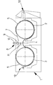
Ein Ausführungsbeispiel der Erfindung wird nachfolgend anhand der Zeichnung näher erläutert; die einzige Figur zeigt schematisch die Seitenansicht einer Zweimuldenmangel (vordere Seitenwand abgenommen).An embodiment of the invention is explained below with reference to the drawing; the single figure shows schematically the side view of a two-cavity ironer (front side wall removed).
Die dargestellte Zweimuldenmangel enthält in einem Gestell 1 in bekannter Weise zwei beheizte Mulden 2, 3, zwischen denen eine ebenfalls beheizte Brücke 4 angeordnet ist. In die Mulden 2, 3 taucht jeweils etwa mit der Hälfte ihres Umfanges eine hohle Walze 5, 6 ein, die mit einer nicht dargestellten Wrasen-Absaugvorrichtung versehen ist. Die Walzen 5, 6 sind an ihren Mantelflächen mit einer federnden Auflage versehen, die aber anders als bei bekannten Walzen nicht durch ein Walzentuch abgedeckt ist.The two-well lack shown contains in a frame 1 in a known manner two heated
Ein Endlostuch aus Polyester oder einem ähnlichen wärme-und feuchtigkeitsbeständigen Kunststoff umschlingt die Walzen 5, 6, wozu es durch den Spalt zwischen der Mulde 2 und der Walze 5 über die Brücke 4 durch den Spalt zwischen der Mulde 3 und der Walze 6 und unter einem Pendelbalken 8 hindurch zurück zur Walze 5 geführt wird.An endless cloth made of polyester or a similar heat and moisture-resistant plastic wraps around the
Das Endlostuch ist aus einer Tuchbahn hergestellt, die durch den beschriebenen Weg innerhalb der Muldenmangel eingefädelt und dann an den Stirnseiten mit einem Reißverschluß verbunden wird. Der Reißverschluß ist an der Seite, welche im Einbauzustand den Mulden 3, 2 zugewandt ist, durch ein überstehendes Stoffstück abgedeckt. Selbstverständlich kann das Tuch 7 auch stirnseitig zusammengenäht werden. Sofern dies die Konstruktion der Muldenmangel im übrigen zuläßt, kann das Endlostuch 7 auch von der Seite her eingeführt werden.The Endlostuch is made of a sheet of fabric, which is threaded through the described path within the trough lack and then connected to the front with a zipper. The zipper is covered on the side which faces the
Der Pendelbalken 8 umfaßt eine freilaufende Walze oder Rolle 9, die im Bereich ihrer gegenüberliegenden Enden an zwei unabhängig voneinander betätigbaren ausfahrbaren Stellmotoren, z.B. Hydraulik- oder Pneumatikzylindern 10, (nur einer in der Zeichnung erkennbar) aufgehängt ist. Im Bereich einer Kante des Tuches 7 befindet sich mindestens eine die Position dieser Kante überwachende Fotozelle (nicht dargestellt).The pendulum beam 8 comprises a free-running roller or
Am in der Zeichnung rechten Ende ist schematisch eine Aufgabestation 12 für die Wäschestücke, am in der Zeichnung linken Ende ein pneumatischer Abstreifer 13 für die auslaufenden Wäschestücke dargestellt. Die Förderrichtung der dargestellten Muldenmangel ist also von rechts nach links.At the right end in the drawing, a
In den vom Tuch 7 umschlossenen Raum mündet eine Absaugleitung 11, über die hier entstehende Dämpfe und dergleichen abgesaugt werden.A
Die beschriebene Muldenmangel funktioniert wie folgt:
- Die Wäschestücke werden an der Auf gabestation in die Maschine eingeführt und gelangen dann in den Spalt zwischen dem
Tuch 7 und derersten Mulde 2. In diesem Spalt übernimmt dasTuch 7 offensichtlich die Funktion des bekannten Walzentuches mit.
- The items of laundry are introduced into the machine at the on-station and then enter the gap between the
cloth 7 and thefirst trough 2. In this gap, thecloth 7 obviously takes on the function of the known roller cloth.
Die Wäschestücke werden dann vom Tuch 7 über die beheizte Brücke 4 und dann in die zweite Mulde 3 eingeführt, wo das Tuch 7 wiederum die Funktion eines Walzentuches übernimmt.The items of laundry are then introduced from the
Am Ausgang der zweiten Mulde 3 richtet der pneumatische Abstreifer 13, der von einer die Vorderkante des Wäschestückes überwachenden Fotozelle angesteuert wird, einen Luftstrahl gegen die auslaufenden Wäschestücke und verhindert so, daß diese vom Tuch 7 mit nach oben genommen werden.At the exit of the
Die Position der Ränder (Kanten) des Tuches 7 wird, wie erwähnt, von mindestens einer Fotozelle überwacht, die an irgendeiner geeigneten Stelle am Wege des Tuches angeordnet sein kann. Solange das Tuch auf der Walze 5, 6 geradeaus läuft, also sich seitlich nicht versetzt, sind die Kolben der Zylinder 10 gleich weit ausgefahren; die Achse der Rolle 9 steht waagerecht und die Rolle 9 übt auf das Tuch 7 einen gleichmäßigen, nach unten gerichteten Druck aus. Der Pendelbalken 8 arbeitet so ausschließlich als Spanneinrichtung für das Tuch 7.As mentioned, the position of the edges (edges) of the
Wenn die Fotozelle feststellt, daß das Tuch 7 auf den Walzen 5, 6 in der einen oder anderen Richtung seitlich auswandert, gibt sie ein entsprechendes Signal ab. Dieses wird von einer entsprechenden, einfachen Steuerelektronik so verarbeitet, daß einer der beiden Zylinder 10 seinen Kolben weiter ausfährt als der andere. Die Rolle 9, deren Achse nunmehr gegen die Horizontale verkippt ist, übt jetzt einen über die Querrichtung des Tuches 7 ungleichmäßigen Druck aus, spannt dieses also ungleichmäßig. Hierdurch wird das Tuch 7 wieder in seine korrekte Position zurückgeführt.If the photocell detects that the
Statt eines Pendelbalkens 8 wird bei einem zweiten, nicht dargestellten Ausführungsbeispiel,der Geradlauf des Tuches 7 durch Schienen gewährleistet, in denen die seitlichen Kanten des.Tuches geführt sind.Instead of a pendulum beam 8, in a second embodiment, not shown, the straight running of the
Bei einem dritten, ebenfalls nicht dargestellten Ausführungsbeispiel wird eine Geradlaufeinrichtung verwendet, wie sie aus der Textilindustrie bekannt ist. Diese umfaßt ein Walzenpaar, durch welches das Tuch 7 (nicht notwendig auf der gesamten Breite) hindurchgeführt wird. Dieses Walzenpaar (oder mindestens eine Walze des Paares) läßt sich nun, wiederum durch eine Fotozelle gesteuert, in der Ebene des Tuches so verschwenken, daß es aus der neutralen Stellung, in welcher die Walzenachse(n) einen Winkel von 90° mit der Bewegungsrichtung des Tuches einschließt, in eine Stellung gelangt, in der die Walzenachse(n) einen stumpfen oder spitzen Winkel mit der Bewegungsrichtung des Tuches 7 einschließt. Auf diese Weise wird auf das Tuch ein Zug senkrecht zur Bewegungsrichtung ausgeübt, der das Tuch 7 wieder in die richtige Position zurückführt.In a third embodiment, also not shown, a straight-running device is used, as is known from the textile industry. This comprises a pair of rollers through which the cloth 7 (not necessarily over the entire width) is passed. This pair of rollers (or at least one roller of the pair) can now, again controlled by a photocell, be pivoted in the plane of the cloth in such a way that it moves out of the neutral position, in which the roller axis (s) forms an angle of 90 ° with the direction of movement of the cloth, reaches a position in which the roller axis (s) forms an obtuse or acute angle with the direction of movement of the
Claims (14)
Applications Claiming Priority (2)
| Application Number | Priority Date | Filing Date | Title |
|---|---|---|---|
| DE3329949 | 1983-08-19 | ||
| DE19833329949 DE3329949C2 (en) | 1983-08-19 | 1983-08-19 | Trough deficiency |
Publications (2)
| Publication Number | Publication Date |
|---|---|
| EP0135077A1 true EP0135077A1 (en) | 1985-03-27 |
| EP0135077B1 EP0135077B1 (en) | 1987-11-11 |
Family
ID=6206928
Family Applications (1)
| Application Number | Title | Priority Date | Filing Date |
|---|---|---|---|
| EP19840108981 Expired EP0135077B1 (en) | 1983-08-19 | 1984-07-28 | Trough calender |
Country Status (5)
| Country | Link |
|---|---|
| EP (1) | EP0135077B1 (en) |
| JP (1) | JPS60222098A (en) |
| DD (1) | DD232078A5 (en) |
| DE (1) | DE3329949C2 (en) |
| ES (1) | ES535043A0 (en) |
Cited By (1)
| Publication number | Priority date | Publication date | Assignee | Title |
|---|---|---|---|---|
| EP2857577A1 (en) * | 2013-10-07 | 2015-04-08 | Herbert Kannegiesser GmbH | Device for mangling laundry |
Citations (19)
| Publication number | Priority date | Publication date | Assignee | Title |
|---|---|---|---|---|
| BE549016A (en) * | 1955-07-08 | |||
| DE101932C (en) * | ||||
| DE126218C (en) * | ||||
| US1624698A (en) * | 1926-10-27 | 1927-04-12 | Robert J Watts | Doffer for ironing machines |
| US1713700A (en) * | 1920-08-14 | 1929-05-21 | American Laundry Mach Co | Apron control |
| US1842297A (en) * | 1928-11-20 | 1932-01-19 | Silverstine Charles | Ironing machine |
| US1968233A (en) * | 1931-11-17 | 1934-07-31 | Gen Linen Supply & Laundry Co | Laundering machine |
| US2643473A (en) * | 1949-02-22 | 1953-06-30 | Newnham Bernard Leslie George | Ironing machine |
| GB713760A (en) * | 1951-06-26 | 1954-08-18 | British Thomson Houston Co Ltd | Improvements relating to means for transversely guiding sheet material passing over rolls |
| GB718436A (en) * | 1951-10-19 | 1954-11-17 | D & J Tullis Ltd | Improvements in or relating to belt conveyors |
| GB762837A (en) * | 1954-06-29 | 1956-12-05 | Goodyear Tire & Rubber | Web positioning device |
| US3096919A (en) * | 1961-08-14 | 1963-07-09 | Goodyear Tire & Rubber | Web guide |
| US3172219A (en) * | 1962-10-19 | 1965-03-09 | Hydraxtor Company | Control apparatus for processing fabric |
| GB1059559A (en) * | 1963-12-23 | 1967-02-22 | Ruthner Othmar | Controlling the transverse register of a web |
| US3407673A (en) * | 1966-05-19 | 1968-10-29 | Raymond J. Slezak | Belt tracking apparatus |
| FR2094357A5 (en) * | 1970-06-18 | 1972-02-04 | Mechin Et Fils Ets | |
| DE2103124A1 (en) * | 1971-01-23 | 1972-07-27 | Schmitz, Werner E" 3250 Hameln | Heat sealing polyester bands - particularly polyester calender bands |
| DE3012392A1 (en) * | 1980-03-29 | 1981-10-08 | Senkingwerk Gmbh Kg, 3200 Hildesheim | Rotary ironing machine with extractor fan - has input sensor which reduces fan speed when feed is interrupted |
| DE2744919C2 (en) * | 1977-10-06 | 1983-03-17 | Hermann Berstorff Maschinenbau Gmbh, 3000 Hannover | Method and device for compensating for a delay in an endless printing belt |
Family Cites Families (6)
| Publication number | Priority date | Publication date | Assignee | Title |
|---|---|---|---|---|
| DE1931907U (en) | 1965-06-24 | 1966-02-03 | Siemens Elektrogeraete Gmbh | ELECTRIC IRONING MACHINE, IN PARTICULAR HOUSEHOLD IRONING MACHINE. |
| CH493683A (en) * | 1968-06-21 | 1970-07-15 | Bravetti Libero | Device for ironing fabrics, linen or garments |
| CS171303B3 (en) * | 1972-11-03 | 1976-10-29 | ||
| DE2407545A1 (en) * | 1974-02-16 | 1975-08-21 | Licentia Gmbh | Ironing machine for bedding - has controlled airflow to prevent build-up of hot damp vapour within the unit |
| US4164083A (en) * | 1977-12-07 | 1979-08-14 | Pennsylvania Sewing Research Corp. | Belt-conveyor ironing machine |
| DE2906275C2 (en) * | 1979-02-19 | 1983-08-04 | Andreas 3400 Göttingen Stichnoth | Device for introducing washed hand towels into a mangle |
-
1983
- 1983-08-19 DE DE19833329949 patent/DE3329949C2/en not_active Expired
-
1984
- 1984-07-28 EP EP19840108981 patent/EP0135077B1/en not_active Expired
- 1984-08-10 DD DD26617084A patent/DD232078A5/en not_active IP Right Cessation
- 1984-08-10 JP JP16662784A patent/JPS60222098A/en active Pending
- 1984-08-10 ES ES535043A patent/ES535043A0/en active Granted
Patent Citations (19)
| Publication number | Priority date | Publication date | Assignee | Title |
|---|---|---|---|---|
| DE101932C (en) * | ||||
| DE126218C (en) * | ||||
| US1713700A (en) * | 1920-08-14 | 1929-05-21 | American Laundry Mach Co | Apron control |
| US1624698A (en) * | 1926-10-27 | 1927-04-12 | Robert J Watts | Doffer for ironing machines |
| US1842297A (en) * | 1928-11-20 | 1932-01-19 | Silverstine Charles | Ironing machine |
| US1968233A (en) * | 1931-11-17 | 1934-07-31 | Gen Linen Supply & Laundry Co | Laundering machine |
| US2643473A (en) * | 1949-02-22 | 1953-06-30 | Newnham Bernard Leslie George | Ironing machine |
| GB713760A (en) * | 1951-06-26 | 1954-08-18 | British Thomson Houston Co Ltd | Improvements relating to means for transversely guiding sheet material passing over rolls |
| GB718436A (en) * | 1951-10-19 | 1954-11-17 | D & J Tullis Ltd | Improvements in or relating to belt conveyors |
| GB762837A (en) * | 1954-06-29 | 1956-12-05 | Goodyear Tire & Rubber | Web positioning device |
| BE549016A (en) * | 1955-07-08 | |||
| US3096919A (en) * | 1961-08-14 | 1963-07-09 | Goodyear Tire & Rubber | Web guide |
| US3172219A (en) * | 1962-10-19 | 1965-03-09 | Hydraxtor Company | Control apparatus for processing fabric |
| GB1059559A (en) * | 1963-12-23 | 1967-02-22 | Ruthner Othmar | Controlling the transverse register of a web |
| US3407673A (en) * | 1966-05-19 | 1968-10-29 | Raymond J. Slezak | Belt tracking apparatus |
| FR2094357A5 (en) * | 1970-06-18 | 1972-02-04 | Mechin Et Fils Ets | |
| DE2103124A1 (en) * | 1971-01-23 | 1972-07-27 | Schmitz, Werner E" 3250 Hameln | Heat sealing polyester bands - particularly polyester calender bands |
| DE2744919C2 (en) * | 1977-10-06 | 1983-03-17 | Hermann Berstorff Maschinenbau Gmbh, 3000 Hannover | Method and device for compensating for a delay in an endless printing belt |
| DE3012392A1 (en) * | 1980-03-29 | 1981-10-08 | Senkingwerk Gmbh Kg, 3200 Hildesheim | Rotary ironing machine with extractor fan - has input sensor which reduces fan speed when feed is interrupted |
Cited By (2)
| Publication number | Priority date | Publication date | Assignee | Title |
|---|---|---|---|---|
| EP2857577A1 (en) * | 2013-10-07 | 2015-04-08 | Herbert Kannegiesser GmbH | Device for mangling laundry |
| US9359716B2 (en) | 2013-10-07 | 2016-06-07 | Herbert Kannegiesser Gmbh | Device for mangling laundry items |
Also Published As
| Publication number | Publication date |
|---|---|
| ES8504290A1 (en) | 1985-04-16 |
| DE3329949A1 (en) | 1985-03-07 |
| EP0135077B1 (en) | 1987-11-11 |
| DD232078A5 (en) | 1986-01-15 |
| ES535043A0 (en) | 1985-04-16 |
| DE3329949C2 (en) | 1986-10-02 |
| JPS60222098A (en) | 1985-11-06 |
Similar Documents
| Publication | Publication Date | Title |
|---|---|---|
| EP1959038B1 (en) | Device for laying a fleece | |
| DE3928454A1 (en) | CLOCK AND TRANSPORT DEVICE | |
| DE1927863B2 (en) | Cross panels for laying carded fiber batt across | |
| DE4116222A1 (en) | RAILWAY APPARATUS | |
| DE2646814C2 (en) | Dryer for material webs guided over endlessly circulating conveyor belts | |
| DD202125A5 (en) | PAPER WEB-guiding device | |
| DE1189919B (en) | Conveying device made up of several conveyor belts arranged one behind the other | |
| EP0135077A1 (en) | Trough calender | |
| DE3443357C1 (en) | Web tension control device on a vertical dryer for webs | |
| DE19936191C2 (en) | Device for the heat treatment of continuous webs | |
| EP0419825B1 (en) | Apparatus for wet treatment of textile sheet-like materials in roped form | |
| CH645142A5 (en) | Apparatus for the retention treatment of a broad-guided textile web | |
| DE4413878C2 (en) | Winding device for simultaneous winding of several towel sheets on a hot iron | |
| EP0016341B1 (en) | Device for feeding washed roll-towels into an ironing machine | |
| EP0793744B1 (en) | Method of feeding laundered items and a trough mangle intended preferably for carrying out this method and a device | |
| CH692730A5 (en) | Enfolding or spine gluing device for book block | |
| DE2906275C2 (en) | Device for introducing washed hand towels into a mangle | |
| DE2829723C3 (en) | Transfer arrangement for the transfer of loose, finely divided material to two closely spaced tail pulleys of endlessly rotating belts | |
| DE19532616C1 (en) | Tenter frame shrink dryer | |
| DE19805320B4 (en) | Device for laying a film web in Z-shaped folds | |
| EP1157621A2 (en) | Method and apparatus for gluing flat materials | |
| DE2616760C2 (en) | ||
| EP0263786B1 (en) | Method and apparatus for handling sheet-like materials in lots | |
| DE3127052C2 (en) | "Device for the dwell treatment of web-shaped textile goods" | |
| CH640023A5 (en) | Dwell shaft for the treatment of textile webs |
Legal Events
| Date | Code | Title | Description |
|---|---|---|---|
| PUAI | Public reference made under article 153(3) epc to a published international application that has entered the european phase |
Free format text: ORIGINAL CODE: 0009012 |
|
| AK | Designated contracting states |
Designated state(s): BE CH FR GB IT LI NL SE |
|
| 17P | Request for examination filed |
Effective date: 19850727 |
|
| 17Q | First examination report despatched |
Effective date: 19860612 |
|
| GRAA | (expected) grant |
Free format text: ORIGINAL CODE: 0009210 |
|
| AK | Designated contracting states |
Kind code of ref document: B1 Designated state(s): BE CH FR GB IT LI NL SE |
|
| ET | Fr: translation filed | ||
| ITF | It: translation for a ep patent filed |
Owner name: STUDIO JAUMANN |
|
| GBT | Gb: translation of ep patent filed (gb section 77(6)(a)/1977) | ||
| PLBE | No opposition filed within time limit |
Free format text: ORIGINAL CODE: 0009261 |
|
| STAA | Information on the status of an ep patent application or granted ep patent |
Free format text: STATUS: NO OPPOSITION FILED WITHIN TIME LIMIT |
|
| 26N | No opposition filed | ||
| PGFP | Annual fee paid to national office [announced via postgrant information from national office to epo] |
Ref country code: SE Payment date: 19910625 Year of fee payment: 8 |
|
| PGFP | Annual fee paid to national office [announced via postgrant information from national office to epo] |
Ref country code: GB Payment date: 19910626 Year of fee payment: 8 |
|
| ITTA | It: last paid annual fee | ||
| PGFP | Annual fee paid to national office [announced via postgrant information from national office to epo] |
Ref country code: FR Payment date: 19920602 Year of fee payment: 9 |
|
| PG25 | Lapsed in a contracting state [announced via postgrant information from national office to epo] |
Ref country code: GB Effective date: 19920728 |
|
| PG25 | Lapsed in a contracting state [announced via postgrant information from national office to epo] |
Ref country code: SE Effective date: 19920729 |
|
| GBPC | Gb: european patent ceased through non-payment of renewal fee |
Effective date: 19920728 |
|
| PGFP | Annual fee paid to national office [announced via postgrant information from national office to epo] |
Ref country code: NL Payment date: 19930731 Year of fee payment: 10 |
|
| PGFP | Annual fee paid to national office [announced via postgrant information from national office to epo] |
Ref country code: CH Payment date: 19931011 Year of fee payment: 10 |
|
| PGFP | Annual fee paid to national office [announced via postgrant information from national office to epo] |
Ref country code: BE Payment date: 19940126 Year of fee payment: 10 |
|
| PG25 | Lapsed in a contracting state [announced via postgrant information from national office to epo] |
Ref country code: FR Effective date: 19940331 |
|
| REG | Reference to a national code |
Ref country code: FR Ref legal event code: ST |
|
| PG25 | Lapsed in a contracting state [announced via postgrant information from national office to epo] |
Ref country code: LI Effective date: 19940731 Ref country code: CH Effective date: 19940731 Ref country code: BE Effective date: 19940731 |
|
| BERE | Be: lapsed |
Owner name: TRANSFERON WASCHEREIMASCHINEN G.M.B.H. Effective date: 19940731 |
|
| EUG | Se: european patent has lapsed |
Ref document number: 84108981.6 Effective date: 19930204 |
|
| PG25 | Lapsed in a contracting state [announced via postgrant information from national office to epo] |
Ref country code: NL Effective date: 19950201 |
|
| NLV4 | Nl: lapsed or anulled due to non-payment of the annual fee | ||
| REG | Reference to a national code |
Ref country code: CH Ref legal event code: PL |