EP0133152B1 - Dispositif pour la connexion de conducteurs auxiliaires à un appareil de commutation ou une combinaison d'appareils de commutation - Google Patents
Dispositif pour la connexion de conducteurs auxiliaires à un appareil de commutation ou une combinaison d'appareils de commutation Download PDFInfo
- Publication number
- EP0133152B1 EP0133152B1 EP84730058A EP84730058A EP0133152B1 EP 0133152 B1 EP0133152 B1 EP 0133152B1 EP 84730058 A EP84730058 A EP 84730058A EP 84730058 A EP84730058 A EP 84730058A EP 0133152 B1 EP0133152 B1 EP 0133152B1
- Authority
- EP
- European Patent Office
- Prior art keywords
- switchgear
- contact elements
- contact
- terminal strip
- group
- Prior art date
- Legal status (The legal status is an assumption and is not a legal conclusion. Google has not performed a legal analysis and makes no representation as to the accuracy of the status listed.)
- Expired
Links
Images
Classifications
-
- H—ELECTRICITY
- H02—GENERATION; CONVERSION OR DISTRIBUTION OF ELECTRIC POWER
- H02B—BOARDS, SUBSTATIONS OR SWITCHING ARRANGEMENTS FOR THE SUPPLY OR DISTRIBUTION OF ELECTRIC POWER
- H02B1/00—Frameworks, boards, panels, desks, casings; Details of substations or switching arrangements
- H02B1/20—Bus-bar or other wiring layouts, e.g. in cubicles, in switchyards
- H02B1/202—Cable lay-outs
-
- H—ELECTRICITY
- H02—GENERATION; CONVERSION OR DISTRIBUTION OF ELECTRIC POWER
- H02B—BOARDS, SUBSTATIONS OR SWITCHING ARRANGEMENTS FOR THE SUPPLY OR DISTRIBUTION OF ELECTRIC POWER
- H02B1/00—Frameworks, boards, panels, desks, casings; Details of substations or switching arrangements
- H02B1/26—Casings; Parts thereof or accessories therefor
- H02B1/30—Cabinet-type casings; Parts thereof or accessories therefor
- H02B1/32—Mounting of devices therein
- H02B1/34—Racks
- H02B1/36—Racks with withdrawable units
-
- H—ELECTRICITY
- H02—GENERATION; CONVERSION OR DISTRIBUTION OF ELECTRIC POWER
- H02B—BOARDS, SUBSTATIONS OR SWITCHING ARRANGEMENTS FOR THE SUPPLY OR DISTRIBUTION OF ELECTRIC POWER
- H02B11/00—Switchgear having carriage withdrawable for isolation
-
- H—ELECTRICITY
- H01—ELECTRIC ELEMENTS
- H01H—ELECTRIC SWITCHES; RELAYS; SELECTORS; EMERGENCY PROTECTIVE DEVICES
- H01H71/00—Details of the protective switches or relays covered by groups H01H73/00 - H01H83/00
- H01H71/08—Terminals; Connections
- H01H2071/086—Low power connections for auxiliary switches, e.g. shunt trip
Definitions
- the invention relates to an arrangement for connecting auxiliary lines to a switching device or a switching device combination with a terminal block attached to the switching device or combination, which has a group of contact elements for auxiliary lines connected to the switching device or combination and a group with the same number of contact elements for auxiliary lines leading away from the switching device or combination, and with a carrier receiving the switching device or combination, e.g. B. according to US-A-4 020301.
- the switching devices can thereby be circuit breakers or contactors, while under a switchgear assembly in the present context, a summary should be read by machines, such as those required for the operation of motor drives, ie contactors, fuses, Schutzgerä t e and command devices.
- the carrier mentioned can be both an open frame or a scaffold to which one or more switching devices or switching device combinations are attached, or it can be a control cabinet in which the switching devices or switching device combinations are used in a manner protected against contact and / or influences from the environment .
- the switchgear or the switchgear and controlgear assembly can be permanently mounted or arranged to be extendable.
- the switching device or the switching device combination includes isolating contacts for main circuits, which during retraction of the device or combination of devices with fixed Mais t divided engage and be separated therefrom upon extension.
- the terminal strip required for the auxiliary lines is usually designed differently depending on the type of installation of the switching device or the switching device combination. For example, when a switchgear is permanently installed, it is customary to choose a normal terminal strip with screw terminals or screwless connection, a terminal point being provided for an auxiliary line on the switch side and for an auxiliary line leading away. If, on the other hand, the switching device is to be arranged so that it can be extended on its support, it is customary to provide a plug-in base instead of a terminal strip onto which a multiple plug for all auxiliary leads leading away can be attached.
- the invention is based on the object to create a system of uniform parts that can be used for the auxiliary lines in all types of installation of the switchgear or switchgear and controlgear assembly.
- the device-side terminal block should be designed as a basic element of such a system.
- the plug-in element is an additional part that is added to the basic version of a switching device in order to prepare it for the extendable arrangement, in which an automatic separation of the auxiliary lines is desired when the switching device is moved beyond the test position.
- the rear position of the plug element creates an arrangement in which the terminal strip is located near the front of the switching device, where it is easily accessible even when the switching device is installed, for example for testing purposes or for attaching or detaching a multiple plug.
- the space lying behind the terminal strip, seen in the depth dimension of the switching device, is used in the respective version by the plug-in element and the base of the auxiliary leads leading away. So far, contact paths were only applicable if the switching devices were already equipped with them at the factory.
- the base can be designed as a contact block, each having a contact member for an auxiliary line leading away and a further contact member galvanically connected to it, which together with a corresponding contact member attached to the plug element along a between the operating position and the test position of the Switching device to travel way interacts in the manner of a sliding contact track.
- Such sliding contact tracks have so far only been applicable if the switching devices were already equipped with them at the factory.
- the unitary clamping strip designed as a base element is assumed.
- the plug-in element is attached to this, which now comes into conductive connection with a contact block attached to the carrier.
- the switching device When the switching device is extended, it first enters the test position, in which only the main current paths are interrupted, while all auxiliary lines remain switched through. The further movement of the switching device into the disconnected position or the complete removal of the switching device from its carrier does not require any handling of the auxiliary lines, because the contact members of the plug element and the contact block automatically disengage and come back into contact with one another when the switching device is inserted into its carrier.
- the contact block and / or its contact members as well as the plug element and / or its contact members be dimensioned for compensating for positional tolerances or provided with a device for compensating for such tolerances. If the arrangement is designed in this way, special precautions when inserting the switching device into its support with regard to the auxiliary lines are unnecessary because, despite the inevitable tolerances, a perfect interaction of the contact members is ensured.
- auxiliary lines While in the arrangement just described, which is intended for retractable switching devices, sliding contact arrangements are provided for the auxiliary lines, flexible auxiliary lines with automatic separation when pulling out the switching device can also be used, for example to achieve a particularly high level of contact reliability in the course of the auxiliary lines. This can be done by the fact that the plug element already mentioned is guided on stationary guide parts in the direction of the disconnected position of the switching device so as to be movable against a spring force and has contact members for the connection of flexible and movable auxiliary lines which are held at the fixed base.
- auxiliary lines In particular, if a large number of auxiliary lines are present, it may be desirable or necessary to provide a way of ensuring that the correct connection of the auxiliary lines, the presence of certain signals or the quality of the line path can be ascertained in a simple manner. For this purpose, it is advisable to provide additional contact elements for test purposes on the terminal strip, a plug to be inserted into it and on the contact block or individual parts thereof. It is expedient to attach these contact members in such condition and position to the parts mentioned that a conventional test probe can be attached or inserted without difficulty.
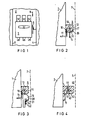
- Figure 1 shows schematically a low-voltage circuit breaker from the front in a switchgear partially shown.
- FIG. 2 shows a simplified representation of a terminal block attached to the side of a circuit breaker.
- FIG. 3 shows the terminal strip according to FIG. 2 together with a multiple plug.
- Figure 4 shows one in particular Use with the multiple plug according to the figure 3 suitable execution of a terminal block.
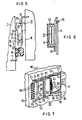
- FIG. 5 shows a three-part arrangement which, in addition to the terminal strip, comprises a plug element and a fixed contact block and which is intended in particular for the pull-out arrangement of switching devices.
- FIG. 6 shows a floating arrangement of the contact block according to FIG. 5 for tolerance compensation.
- FIG. 7 shows a perspective view of another embodiment for switchgear units arranged in a retractable manner, in which flexible auxiliary lines are provided to bridge the path of the switchgear unit.
- the Niedersp n Vietnamese circuit breaker 1 shown in Figure 1 is terminated switchgear 2 in a direction shown permanently installed.
- the components used for fastening as well as supply and discharge busbars are not shown, since these parts are not required for an understanding of the invention.
- the circuit breaker 1 is arranged between two walls 3 and 4, through which the switchgear 2 is divided into sections or fields.
- the switchgear can either be open or cover plates or doors can be provided to protect the switchgear against contact as well as against environmental influences.
- a terminal strip 5 is arranged, which is used to connect power lines. These are to be understood as those electrical connections that are provided in addition to the main current paths between the circuit breaker and a control room for the transmission of message and control signals.
- Figure 2 shows details of the terminal block 5.
- the terminal block is from above, i. H. shown in the direction of arrow 6 shown in FIG.
- the circuit breaker 1 is shown broken off, while an arbitrary limitation of the installation space of the circuit breaker 1 is indicated by a dashed line, for. B. a support bracket or an intermediate wall of the switchgear 2.
- the terminal block 5 has on its side facing the front of the circuit breaker 1 a contact member 10, into which a switch-side auxiliary line 11 is inserted. This can be connected to an additional device of any kind, for example an auxiliary switch or a remote release.
- a contact member 10 In addition to the contact member 10 and in a galvanic connection therewith, there is a further contact member 12 on the front side of the terminal strip 5, while a third contact element 13 is likewise arranged in a galvanic connection with the contact element 10 on the rear side.
- the terminal strip Corresponding to the number of auxiliary lines on the switch side, the terminal strip has a large number of these arrangements of contact members
- the design of the contact points 10, 12 and 13 is arbitrary.
- the contact elements can be designed as screw terminals, as pressure clamps or as self-clamping contact elements. It is also possible to combine different designs of contact members with one another.
- a multiple plug 15 is shown, to which all auxiliary lines 14 on the system side are connected.
- the multiple plug 15 in turn has contact pins that can be inserted into the contact members 12 of the terminal block 5.
- the terminal block 40 according to FIG. 4 accordingly has three contact members 41, 42 and 43 on its side facing the front of the circuit breaker 1.
- the contact members 41 and 42 correspond to the contact members 10 and 12 in FIG. 1.
- the contact member 43 is specifically designed to engage a contact pin of a multiple connector, for example the multiple connector 15 in FIG. 3.
- the terminal block 40 On its rear side, the terminal block 40 has a contact member 44, which Contact member 23 in Figure 2 corresponds.
- a front connector (15 in FIG. 3) is equally suitable for a fixed installation of the circuit breaker 1 or a retractable arrangement. In both cases, it is necessary to remove the plug from the terminal strip 5 or 40 before the circuit breaker is removed from its carrier.
- FIG. 5 The arrangement shown in FIG. 5 is provided especially for the case in which the circuit breaker 1 is inside the switchgear 2 is arranged extendable in a slide-in frame 16.
- a terminal strip 5 is again provided in an unchanged design, to whose contact elements 10, as in the previous examples, the switch-side auxiliary lines 11 are connected.
- the system-side auxiliary lines 14 are, however, connected to a contact block 17 which serves as a support point and which is fastened to the slide-in frame 16.
- This contact block has one of the number of auxiliary lines 14 corresponding number of contact sockets 21 or similar components which have such a length that a connection of the auxiliary lines is maintained via the path to be covered from the operating position to the test position of the circuit breaker 1.
- a plug-in element 18 interacts with the contact sockets of the contact block 17 and has on its side facing the terminal strip 5 a multiplicity of contact pins 19 which are intended to engage in the contact members 13 of the terminal strip 5.
- the plug element 18 On its opposite side, ie facing the rear side of the circuit breaker 1, the plug element 18 has a number of contact pins 20 which cooperate with the contact sockets 21 of the contact block 17 in the manner of sliding contacts.
- FIG. 6 An example of this is shown in FIG. 6.
- the contact block 17 with its contact sockets 21 is located in a holder 23 which surrounds the contact block 17 at a distance.
- Spring elements for example in the form of leaf springs 24, are arranged in the intermediate space and center the contact block 17 approximately centrally in the holder 23 in the idle state.
- the contact block 17 can align itself with the contact elements 21 of the plug element 20 (FIG. 4), which ensures perfect interaction.
- the holder 23 can be screwed to the slide-in frame 16 (lower screw 25) or fastened by means of a snap connection (upper latch 26).
- the plug element 18 can also be fastened to the side wall of the circuit breaker 1.
- the plug-in element 18 can also be designed such that it is held only by the terminal strip 5 or 40.
- locking elements in the form of resilient plastic noses or similar links are particularly suitable.
- both the terminal strip 5 and the multiple connector 15 and the contact block 17 are provided with a bevelled front edge 27, 28 and 29, respectively, for the attachment of uniformly designed and labeled number strips 30, 31 and 32 serve to designate the terminals.
- the terminal block 5, the multiple connector 15 and the contact block 17 are provided with contact members for testing purposes in order to be able to examine the correct connection of the auxiliary lines and the correct contact.
- These contact points 33 are used to put on or insert a test probe and are provided on the terminal strip 5 next to the contact elements 12.
- Corresponding contact points on the multiple plug 15 according to FIG. 3 are denoted by 34 and on the contact block 17 by 35.
- FIG. 1 A further exemplary embodiment of an automatic arrangement for connecting or disconnecting auxiliary lines to an extendable switching device is now made possible on the basis of FIG.
- a terminal strip 52 On a side wall 50 of a circuit breaker 51, a terminal strip 52 is fastened, on the end face 54 of which faces the front side 53 of the circuit breaker 51, two rows of contact members for auxiliary lines are arranged side by side.
- the row of contact members 55 shown on the left in the figure is provided for the switch-side auxiliary lines 56, while the right side of contact members 57 is unoccupied in the present example and can be occupied, for example, with individual auxiliary leads leading away when the circuit breaker 51 is permanently installed.
- a side wall 60 of a slide-in frame is also shown in section, in which the circuit breaker 51 is slidably guided.
- the bundle of auxiliary lines is fanned out for connection to the contact members of a plug-in unit 63, which has a holder 64 for fastening the auxiliary lines.
- the plug-in unit 63 is provided with displaceable guides on an upper guide rail 65 and a corresponding lower guide rail 66, of which in the Figure only the upper extension 67 is visible.
- the terminal strip 52 and the plug-in unit 63 interact with one another in the manner of a multiple plug-in connection.
- the small strip 52 is provided on its rear side facing the plug-in unit 63 with contact pins 70, which are matched by corresponding contact sockets 71 of the plug-in unit 63.
- the plug-in unit 63 rests on stop surfaces of the guide rails 65 and 66, of which the upper stop 72 is shown in FIG.
- the plug-in unit 63 is pressed against these stops by two helical compression springs 73 which are arranged near the guide rails 65 and 66 and are partially enclosed by the legs thereof.
- the mentioned coil springs are dimensioned such that a possible stiffness of the auxiliary lines 62 and the friction of the plug-in unit 63 in the guide rails 65 and 66 are overcome and the plug-in unit 63 bears against the stops 72 with such pretension that the contact pins 70 of the terminal strip 52 with the Contact sockets 71 of the plug-in unit 63 can properly engage.
- the mutual alignment required for this is due to the fact that the terminal strip 52 is also guided in the guide rails 65 and 66 by means of corresponding lugs 74.
- the guide rails 65 and 66 are widened at their front ends 75 and 76 in such a way that a funnel-like widened opening results.
- the possibility of mutual alignment, which is also required, can be achieved by a floating fastening of the terminal strip 52 to the side wall 50 of the circuit breaker 51 or by a corresponding mobility of the guide rails 65 and 66, for example by a suitable design of their holding angles 77 and 78.
- each is the auxiliary line of a circuit breaker.
- a low-voltage contactor or medium-voltage contactor can thus take the place of the circuit breaker mentioned in each case.
- the invention is also applicable to switchgear and controlgear assemblies such as are used for the operation of electric motors or motor drives and which, in addition to one or more contactors, may contain further devices such as fuses, triggers, command devices and similar parts.
- auxiliary lines required for each switchgear or switchgear and controlgear assembly can be very different, it is advisable to dimension the described terminal strips and the other elements that interact with them in accordance with a frequently required number of auxiliary lines, for example 8-pin or 12-pin . For a larger number of auxiliary lines, men can then use a corresponding multiple of the uniformly designed terminal strips and associated elements.
- terminal strips and the parts interacting therewith and the contact members contained therein are shown in simplified form because the arrangement and mutual assignment of the parts is more important than their nature for the invention.
- all suitable principles of contact members, as well as all suitable conductive and insulating materials, as well as shaping methods, can be used to produce the terminal strips and the other parts described. This applies analogously to the attachment of the parts to the switchgear and to fixed parts of scaffolding or switchgear.
Claims (6)
Priority Applications (1)
| Application Number | Priority Date | Filing Date | Title |
|---|---|---|---|
| AT84730058T ATE29347T1 (de) | 1983-06-10 | 1984-05-30 | Anordnung zum anschluss von hilfsleitungen an ein schaltgeraet oder eine schaltgeraetekombination. |
Applications Claiming Priority (2)
| Application Number | Priority Date | Filing Date | Title |
|---|---|---|---|
| DE3321497 | 1983-06-10 | ||
| DE3321497A DE3321497A1 (de) | 1983-06-10 | 1983-06-10 | Anordnung zum anschluss von hilfsleitungen an ein schaltgeraet oder eine schaltgeraetekombination |
Publications (2)
| Publication Number | Publication Date |
|---|---|
| EP0133152A1 EP0133152A1 (fr) | 1985-02-13 |
| EP0133152B1 true EP0133152B1 (fr) | 1987-09-02 |
Family
ID=6201480
Family Applications (1)
| Application Number | Title | Priority Date | Filing Date |
|---|---|---|---|
| EP84730058A Expired EP0133152B1 (fr) | 1983-06-10 | 1984-05-30 | Dispositif pour la connexion de conducteurs auxiliaires à un appareil de commutation ou une combinaison d'appareils de commutation |
Country Status (5)
| Country | Link |
|---|---|
| EP (1) | EP0133152B1 (fr) |
| JP (1) | JPH0724173B2 (fr) |
| AT (1) | ATE29347T1 (fr) |
| DE (2) | DE3321497A1 (fr) |
| IN (1) | IN161399B (fr) |
Cited By (1)
| Publication number | Priority date | Publication date | Assignee | Title |
|---|---|---|---|---|
| DE4041950C1 (en) * | 1990-12-27 | 1992-06-04 | Kloeckner-Moeller Gmbh, 5300 Bonn, De | Framework for switch cabinet - has numbered holes in shanks increasing in direction of three coordinates from reference point simplifying EDP-supported assembly |
Families Citing this family (16)
| Publication number | Priority date | Publication date | Assignee | Title |
|---|---|---|---|---|
| DE3418868A1 (de) * | 1984-05-21 | 1985-11-21 | Siemens Ag | Steckverbinder |
| DE3834820A1 (de) * | 1988-10-13 | 1990-04-19 | Licentia Gmbh | Hilfsschalteranordnung fuer einen schaltereinschub |
| DE58905315D1 (de) * | 1988-10-10 | 1993-09-23 | Licentia Gmbh | Nebenstromkreise fuer einen schaltereinschub. |
| FR2686452A1 (fr) * | 1992-01-22 | 1993-07-23 | Merlin Gerin | Disjoncteur electrique embrochable comportant un dispositif de connexion electrique. |
| DE59405140D1 (de) * | 1993-04-21 | 1998-03-05 | Sace Spa | Schalter mit Hilfsstromkreisen |
| FR2772199B1 (fr) | 1997-12-09 | 2000-01-28 | Schneider Electric Sa | Chassis fixe pour un interrupteur electrique debrochable |
| DE19802921A1 (de) * | 1998-01-21 | 1999-07-22 | Siemens Ag | Niederspannungs-Leistungsschalter mit einem Hilfsauslöser |
| EP0952650A3 (fr) * | 1998-04-20 | 1999-11-24 | CUBIC-Modulsystem A/S | Système d'interrupteur du type tiroir |
| FR2796768B1 (fr) * | 1999-07-20 | 2001-11-02 | Schneider Electric Ind Sa | Dispositif de connexion d'auxiliaire pour un appareillage electrique de coupure debrochable |
| DE202006006626U1 (de) * | 2006-04-26 | 2007-09-06 | Weidmüller Interface GmbH & Co. KG | Verbindungs- und Schaltvorrichtung |
| DE102008010418A1 (de) * | 2008-02-21 | 2009-08-27 | Moeller Gmbh | Vorrichtung zur Verbindung von Steuerstromleitungen |
| US7965493B2 (en) * | 2009-08-05 | 2011-06-21 | Eaton Corporation | Motor control center and subunit therefor |
| DE102011006830A1 (de) * | 2011-04-06 | 2012-10-11 | Siemens Aktiengesellschaft | Anordnung mit einem Schalter, insbesondere mit einem Niederspannungsleistungsschalter |
| US9490086B2 (en) | 2014-12-23 | 2016-11-08 | Eaton Corporation | Molded case circuit breaker accessory wiring improvement |
| US9742164B2 (en) | 2015-06-16 | 2017-08-22 | General Electric Company | Secondary disconnect assembly for a switching device |
| FR3121312B1 (fr) * | 2021-03-26 | 2024-02-02 | Schneider Electric Ind Sas | Tiroir de contrôle-commande pour armoire électrique de raccordement et armoire électrique de raccordement comprenant un tel tiroir de contrôle-commande |
Citations (1)
| Publication number | Priority date | Publication date | Assignee | Title |
|---|---|---|---|---|
| US2740944A (en) * | 1950-10-17 | 1956-04-03 | Telephone Mfg Co Ltd | Mounting arrangements for electrical apparatus |
Family Cites Families (4)
| Publication number | Priority date | Publication date | Assignee | Title |
|---|---|---|---|---|
| US4020301A (en) * | 1975-04-14 | 1977-04-26 | General Electric Company | Drawout apparatus having improved secondary contact mounting provisions |
| JPS5452077U (fr) * | 1977-09-19 | 1979-04-11 | ||
| JPS5580844U (fr) * | 1979-09-20 | 1980-06-04 | ||
| FR2498380A1 (fr) * | 1981-01-16 | 1982-07-23 | Alsthom Cgee | Connecteur pour equipement electrique en tiroir |
-
1983
- 1983-06-10 DE DE3321497A patent/DE3321497A1/de not_active Withdrawn
-
1984
- 1984-05-17 IN IN341/CAL/84A patent/IN161399B/en unknown
- 1984-05-30 EP EP84730058A patent/EP0133152B1/fr not_active Expired
- 1984-05-30 AT AT84730058T patent/ATE29347T1/de not_active IP Right Cessation
- 1984-05-30 DE DE8484730058T patent/DE3465851D1/de not_active Expired
- 1984-06-08 JP JP59118052A patent/JPH0724173B2/ja not_active Expired - Lifetime
Patent Citations (1)
| Publication number | Priority date | Publication date | Assignee | Title |
|---|---|---|---|---|
| US2740944A (en) * | 1950-10-17 | 1956-04-03 | Telephone Mfg Co Ltd | Mounting arrangements for electrical apparatus |
Cited By (1)
| Publication number | Priority date | Publication date | Assignee | Title |
|---|---|---|---|---|
| DE4041950C1 (en) * | 1990-12-27 | 1992-06-04 | Kloeckner-Moeller Gmbh, 5300 Bonn, De | Framework for switch cabinet - has numbered holes in shanks increasing in direction of three coordinates from reference point simplifying EDP-supported assembly |
Also Published As
| Publication number | Publication date |
|---|---|
| JPH0724173B2 (ja) | 1995-03-15 |
| ATE29347T1 (de) | 1987-09-15 |
| IN161399B (fr) | 1987-11-28 |
| DE3321497A1 (de) | 1984-12-13 |
| DE3465851D1 (en) | 1987-10-08 |
| JPS609014A (ja) | 1985-01-18 |
| EP0133152A1 (fr) | 1985-02-13 |
Similar Documents
| Publication | Publication Date | Title |
|---|---|---|
| EP0133152B1 (fr) | Dispositif pour la connexion de conducteurs auxiliaires à un appareil de commutation ou une combinaison d'appareils de commutation | |
| DE4438800C1 (de) | Anschlußklemmenblock mit Elektronikmodul | |
| EP1029390B1 (fr) | Ensemble d'appareils de commutation apte a la communication | |
| EP1856709B1 (fr) | Commutateur electromecanique | |
| AT399064B (de) | Elektrische schaltvorrichtung mit thermischem schutz | |
| EP0753916A2 (fr) | Système d'adaptateur barres conductrices | |
| DE10003267C2 (de) | Stromkreisunterbrechereinrichtung | |
| EP1312138B1 (fr) | Appareil electrique comprenant un raccord pour conducteur de bouclage | |
| EP0477664A1 (fr) | Insert de protection pour réglette à bornes installée dans un équipement de télécommunication, en particulier dans un poste annexe téléphonique | |
| DE2046430C3 (de) | Prüfanordnung zum Anschalten von zu prüfenden Ausrüstungen, wie Relaisschutz- und Automatikausrüstungen, an Prüfapparate | |
| EP2671286A1 (fr) | Bloc de distributeur | |
| WO2022106262A1 (fr) | Borne pour lignes électriques | |
| EP1356548B1 (fr) | Dispositif de contact pour la liaison liberable d'un bloc d'assemblage mobile avec des rails conducteurs fixes | |
| DE4438215C2 (de) | NH-Sicherungs-Lasttrennschalter mit Sicherungsüberwachung | |
| DE102009045121A1 (de) | System zur Verteilung von elektrischer Energie | |
| WO1999019954A1 (fr) | Adaptateur pour barres omnibus | |
| EP2685562B1 (fr) | Appareil de commutation d'installation avec bornes de raccordement | |
| DE2246964C3 (de) | Schutzschaltereinrichtung | |
| WO2009030719A1 (fr) | Commutateur comprenant au moins deux niveaux de commutation | |
| EP1676288B1 (fr) | Dispositif d'installation | |
| DE1168990B (de) | Nulleiter-Trennklemmleiste | |
| DE10261927B4 (de) | Flachkabel-System | |
| EP3281215B1 (fr) | Système convertisseur de courant et sectionneur équipé d'un tel système | |
| EP0339492B1 (fr) | Dispositif pour connecter facultativement des lignes électriques | |
| DE202014103863U1 (de) | Sicherungsmodul |
Legal Events
| Date | Code | Title | Description |
|---|---|---|---|
| PUAI | Public reference made under article 153(3) epc to a published international application that has entered the european phase |
Free format text: ORIGINAL CODE: 0009012 |
|
| AK | Designated contracting states |
Designated state(s): AT BE CH DE FR GB IT LI LU NL SE |
|
| 17P | Request for examination filed |
Effective date: 19850328 |
|
| 17Q | First examination report despatched |
Effective date: 19860128 |
|
| GRAA | (expected) grant |
Free format text: ORIGINAL CODE: 0009210 |
|
| AK | Designated contracting states |
Kind code of ref document: B1 Designated state(s): AT BE CH DE FR GB IT LI LU NL SE |
|
| PG25 | Lapsed in a contracting state [announced via postgrant information from national office to epo] |
Ref country code: BE Effective date: 19870902 |
|
| REF | Corresponds to: |
Ref document number: 29347 Country of ref document: AT Date of ref document: 19870915 Kind code of ref document: T |
|
| REF | Corresponds to: |
Ref document number: 3465851 Country of ref document: DE Date of ref document: 19871008 |
|
| ET | Fr: translation filed | ||
| ITF | It: translation for a ep patent filed |
Owner name: STUDIO JAUMANN |
|
| GBT | Gb: translation of ep patent filed (gb section 77(6)(a)/1977) | ||
| PLBE | No opposition filed within time limit |
Free format text: ORIGINAL CODE: 0009261 |
|
| STAA | Information on the status of an ep patent application or granted ep patent |
Free format text: STATUS: NO OPPOSITION FILED WITHIN TIME LIMIT |
|
| 26N | No opposition filed | ||
| PGFP | Annual fee paid to national office [announced via postgrant information from national office to epo] |
Ref country code: AT Payment date: 19910424 Year of fee payment: 8 |
|
| PGFP | Annual fee paid to national office [announced via postgrant information from national office to epo] |
Ref country code: LU Payment date: 19910516 Year of fee payment: 8 |
|
| ITTA | It: last paid annual fee | ||
| EPTA | Lu: last paid annual fee | ||
| PG25 | Lapsed in a contracting state [announced via postgrant information from national office to epo] |
Ref country code: LU Free format text: LAPSE BECAUSE OF NON-PAYMENT OF DUE FEES Effective date: 19920530 Ref country code: AT Effective date: 19920530 |
|
| EAL | Se: european patent in force in sweden |
Ref document number: 84730058.9 |
|
| PGFP | Annual fee paid to national office [announced via postgrant information from national office to epo] |
Ref country code: NL Payment date: 19950531 Year of fee payment: 12 |
|
| PGFP | Annual fee paid to national office [announced via postgrant information from national office to epo] |
Ref country code: CH Payment date: 19950817 Year of fee payment: 12 |
|
| PGFP | Annual fee paid to national office [announced via postgrant information from national office to epo] |
Ref country code: GB Payment date: 19960419 Year of fee payment: 13 |
|
| PGFP | Annual fee paid to national office [announced via postgrant information from national office to epo] |
Ref country code: SE Payment date: 19960514 Year of fee payment: 13 |
|
| PGFP | Annual fee paid to national office [announced via postgrant information from national office to epo] |
Ref country code: FR Payment date: 19960523 Year of fee payment: 13 |
|
| PG25 | Lapsed in a contracting state [announced via postgrant information from national office to epo] |
Ref country code: LI Effective date: 19960531 Ref country code: CH Effective date: 19960531 |
|
| PGFP | Annual fee paid to national office [announced via postgrant information from national office to epo] |
Ref country code: DE Payment date: 19960719 Year of fee payment: 13 |
|
| PG25 | Lapsed in a contracting state [announced via postgrant information from national office to epo] |
Ref country code: NL Effective date: 19961201 |
|
| REG | Reference to a national code |
Ref country code: CH Ref legal event code: PL |
|
| NLV4 | Nl: lapsed or anulled due to non-payment of the annual fee |
Effective date: 19961201 |
|
| PG25 | Lapsed in a contracting state [announced via postgrant information from national office to epo] |
Ref country code: GB Effective date: 19970530 |
|
| PG25 | Lapsed in a contracting state [announced via postgrant information from national office to epo] |
Ref country code: SE Effective date: 19970531 |
|
| GBPC | Gb: european patent ceased through non-payment of renewal fee |
Effective date: 19970530 |
|
| PG25 | Lapsed in a contracting state [announced via postgrant information from national office to epo] |
Ref country code: FR Free format text: LAPSE BECAUSE OF NON-PAYMENT OF DUE FEES Effective date: 19980130 |
|
| EUG | Se: european patent has lapsed |
Ref document number: 84730058.9 |
|
| PG25 | Lapsed in a contracting state [announced via postgrant information from national office to epo] |
Ref country code: DE Free format text: LAPSE BECAUSE OF NON-PAYMENT OF DUE FEES Effective date: 19980203 |
|
| REG | Reference to a national code |
Ref country code: FR Ref legal event code: ST |