EP0133152B1 - Arrangement for the connection of auxiliary conductors to a switchgear or a switchgear combination - Google Patents
Arrangement for the connection of auxiliary conductors to a switchgear or a switchgear combination Download PDFInfo
- Publication number
- EP0133152B1 EP0133152B1 EP84730058A EP84730058A EP0133152B1 EP 0133152 B1 EP0133152 B1 EP 0133152B1 EP 84730058 A EP84730058 A EP 84730058A EP 84730058 A EP84730058 A EP 84730058A EP 0133152 B1 EP0133152 B1 EP 0133152B1
- Authority
- EP
- European Patent Office
- Prior art keywords
- switchgear
- contact elements
- contact
- terminal strip
- group
- Prior art date
- Legal status (The legal status is an assumption and is not a legal conclusion. Google has not performed a legal analysis and makes no representation as to the accuracy of the status listed.)
- Expired
Links
Images
Classifications
-
- H—ELECTRICITY
- H02—GENERATION; CONVERSION OR DISTRIBUTION OF ELECTRIC POWER
- H02B—BOARDS, SUBSTATIONS OR SWITCHING ARRANGEMENTS FOR THE SUPPLY OR DISTRIBUTION OF ELECTRIC POWER
- H02B1/00—Frameworks, boards, panels, desks, casings; Details of substations or switching arrangements
- H02B1/20—Bus-bar or other wiring layouts, e.g. in cubicles, in switchyards
- H02B1/202—Cable lay-outs
-
- H—ELECTRICITY
- H02—GENERATION; CONVERSION OR DISTRIBUTION OF ELECTRIC POWER
- H02B—BOARDS, SUBSTATIONS OR SWITCHING ARRANGEMENTS FOR THE SUPPLY OR DISTRIBUTION OF ELECTRIC POWER
- H02B1/00—Frameworks, boards, panels, desks, casings; Details of substations or switching arrangements
- H02B1/26—Casings; Parts thereof or accessories therefor
- H02B1/30—Cabinet-type casings; Parts thereof or accessories therefor
- H02B1/32—Mounting of devices therein
- H02B1/34—Racks
- H02B1/36—Racks with withdrawable units
-
- H—ELECTRICITY
- H02—GENERATION; CONVERSION OR DISTRIBUTION OF ELECTRIC POWER
- H02B—BOARDS, SUBSTATIONS OR SWITCHING ARRANGEMENTS FOR THE SUPPLY OR DISTRIBUTION OF ELECTRIC POWER
- H02B11/00—Switchgear having carriage withdrawable for isolation
-
- H—ELECTRICITY
- H01—ELECTRIC ELEMENTS
- H01H—ELECTRIC SWITCHES; RELAYS; SELECTORS; EMERGENCY PROTECTIVE DEVICES
- H01H71/00—Details of the protective switches or relays covered by groups H01H73/00 - H01H83/00
- H01H71/08—Terminals; Connections
- H01H2071/086—Low power connections for auxiliary switches, e.g. shunt trip
Definitions
- the invention relates to an arrangement for connecting auxiliary lines to a switching device or a switching device combination with a terminal block attached to the switching device or combination, which has a group of contact elements for auxiliary lines connected to the switching device or combination and a group with the same number of contact elements for auxiliary lines leading away from the switching device or combination, and with a carrier receiving the switching device or combination, e.g. B. according to US-A-4 020301.
- the switching devices can thereby be circuit breakers or contactors, while under a switchgear assembly in the present context, a summary should be read by machines, such as those required for the operation of motor drives, ie contactors, fuses, Schutzgerä t e and command devices.
- the carrier mentioned can be both an open frame or a scaffold to which one or more switching devices or switching device combinations are attached, or it can be a control cabinet in which the switching devices or switching device combinations are used in a manner protected against contact and / or influences from the environment .
- the switchgear or the switchgear and controlgear assembly can be permanently mounted or arranged to be extendable.
- the switching device or the switching device combination includes isolating contacts for main circuits, which during retraction of the device or combination of devices with fixed Mais t divided engage and be separated therefrom upon extension.
- the terminal strip required for the auxiliary lines is usually designed differently depending on the type of installation of the switching device or the switching device combination. For example, when a switchgear is permanently installed, it is customary to choose a normal terminal strip with screw terminals or screwless connection, a terminal point being provided for an auxiliary line on the switch side and for an auxiliary line leading away. If, on the other hand, the switching device is to be arranged so that it can be extended on its support, it is customary to provide a plug-in base instead of a terminal strip onto which a multiple plug for all auxiliary leads leading away can be attached.
- the invention is based on the object to create a system of uniform parts that can be used for the auxiliary lines in all types of installation of the switchgear or switchgear and controlgear assembly.
- the device-side terminal block should be designed as a basic element of such a system.
- the plug-in element is an additional part that is added to the basic version of a switching device in order to prepare it for the extendable arrangement, in which an automatic separation of the auxiliary lines is desired when the switching device is moved beyond the test position.
- the rear position of the plug element creates an arrangement in which the terminal strip is located near the front of the switching device, where it is easily accessible even when the switching device is installed, for example for testing purposes or for attaching or detaching a multiple plug.
- the space lying behind the terminal strip, seen in the depth dimension of the switching device, is used in the respective version by the plug-in element and the base of the auxiliary leads leading away. So far, contact paths were only applicable if the switching devices were already equipped with them at the factory.
- the base can be designed as a contact block, each having a contact member for an auxiliary line leading away and a further contact member galvanically connected to it, which together with a corresponding contact member attached to the plug element along a between the operating position and the test position of the Switching device to travel way interacts in the manner of a sliding contact track.
- Such sliding contact tracks have so far only been applicable if the switching devices were already equipped with them at the factory.
- the unitary clamping strip designed as a base element is assumed.
- the plug-in element is attached to this, which now comes into conductive connection with a contact block attached to the carrier.
- the switching device When the switching device is extended, it first enters the test position, in which only the main current paths are interrupted, while all auxiliary lines remain switched through. The further movement of the switching device into the disconnected position or the complete removal of the switching device from its carrier does not require any handling of the auxiliary lines, because the contact members of the plug element and the contact block automatically disengage and come back into contact with one another when the switching device is inserted into its carrier.
- the contact block and / or its contact members as well as the plug element and / or its contact members be dimensioned for compensating for positional tolerances or provided with a device for compensating for such tolerances. If the arrangement is designed in this way, special precautions when inserting the switching device into its support with regard to the auxiliary lines are unnecessary because, despite the inevitable tolerances, a perfect interaction of the contact members is ensured.
- auxiliary lines While in the arrangement just described, which is intended for retractable switching devices, sliding contact arrangements are provided for the auxiliary lines, flexible auxiliary lines with automatic separation when pulling out the switching device can also be used, for example to achieve a particularly high level of contact reliability in the course of the auxiliary lines. This can be done by the fact that the plug element already mentioned is guided on stationary guide parts in the direction of the disconnected position of the switching device so as to be movable against a spring force and has contact members for the connection of flexible and movable auxiliary lines which are held at the fixed base.
- auxiliary lines In particular, if a large number of auxiliary lines are present, it may be desirable or necessary to provide a way of ensuring that the correct connection of the auxiliary lines, the presence of certain signals or the quality of the line path can be ascertained in a simple manner. For this purpose, it is advisable to provide additional contact elements for test purposes on the terminal strip, a plug to be inserted into it and on the contact block or individual parts thereof. It is expedient to attach these contact members in such condition and position to the parts mentioned that a conventional test probe can be attached or inserted without difficulty.
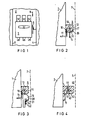
- Figure 1 shows schematically a low-voltage circuit breaker from the front in a switchgear partially shown.
- FIG. 2 shows a simplified representation of a terminal block attached to the side of a circuit breaker.
- FIG. 3 shows the terminal strip according to FIG. 2 together with a multiple plug.
- Figure 4 shows one in particular Use with the multiple plug according to the figure 3 suitable execution of a terminal block.
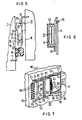
- FIG. 5 shows a three-part arrangement which, in addition to the terminal strip, comprises a plug element and a fixed contact block and which is intended in particular for the pull-out arrangement of switching devices.
- FIG. 6 shows a floating arrangement of the contact block according to FIG. 5 for tolerance compensation.
- FIG. 7 shows a perspective view of another embodiment for switchgear units arranged in a retractable manner, in which flexible auxiliary lines are provided to bridge the path of the switchgear unit.
- the Niedersp n Vietnamese circuit breaker 1 shown in Figure 1 is terminated switchgear 2 in a direction shown permanently installed.
- the components used for fastening as well as supply and discharge busbars are not shown, since these parts are not required for an understanding of the invention.
- the circuit breaker 1 is arranged between two walls 3 and 4, through which the switchgear 2 is divided into sections or fields.
- the switchgear can either be open or cover plates or doors can be provided to protect the switchgear against contact as well as against environmental influences.
- a terminal strip 5 is arranged, which is used to connect power lines. These are to be understood as those electrical connections that are provided in addition to the main current paths between the circuit breaker and a control room for the transmission of message and control signals.
- Figure 2 shows details of the terminal block 5.
- the terminal block is from above, i. H. shown in the direction of arrow 6 shown in FIG.
- the circuit breaker 1 is shown broken off, while an arbitrary limitation of the installation space of the circuit breaker 1 is indicated by a dashed line, for. B. a support bracket or an intermediate wall of the switchgear 2.
- the terminal block 5 has on its side facing the front of the circuit breaker 1 a contact member 10, into which a switch-side auxiliary line 11 is inserted. This can be connected to an additional device of any kind, for example an auxiliary switch or a remote release.
- a contact member 10 In addition to the contact member 10 and in a galvanic connection therewith, there is a further contact member 12 on the front side of the terminal strip 5, while a third contact element 13 is likewise arranged in a galvanic connection with the contact element 10 on the rear side.
- the terminal strip Corresponding to the number of auxiliary lines on the switch side, the terminal strip has a large number of these arrangements of contact members
- the design of the contact points 10, 12 and 13 is arbitrary.
- the contact elements can be designed as screw terminals, as pressure clamps or as self-clamping contact elements. It is also possible to combine different designs of contact members with one another.
- a multiple plug 15 is shown, to which all auxiliary lines 14 on the system side are connected.
- the multiple plug 15 in turn has contact pins that can be inserted into the contact members 12 of the terminal block 5.
- the terminal block 40 according to FIG. 4 accordingly has three contact members 41, 42 and 43 on its side facing the front of the circuit breaker 1.
- the contact members 41 and 42 correspond to the contact members 10 and 12 in FIG. 1.
- the contact member 43 is specifically designed to engage a contact pin of a multiple connector, for example the multiple connector 15 in FIG. 3.
- the terminal block 40 On its rear side, the terminal block 40 has a contact member 44, which Contact member 23 in Figure 2 corresponds.
- a front connector (15 in FIG. 3) is equally suitable for a fixed installation of the circuit breaker 1 or a retractable arrangement. In both cases, it is necessary to remove the plug from the terminal strip 5 or 40 before the circuit breaker is removed from its carrier.
- FIG. 5 The arrangement shown in FIG. 5 is provided especially for the case in which the circuit breaker 1 is inside the switchgear 2 is arranged extendable in a slide-in frame 16.
- a terminal strip 5 is again provided in an unchanged design, to whose contact elements 10, as in the previous examples, the switch-side auxiliary lines 11 are connected.
- the system-side auxiliary lines 14 are, however, connected to a contact block 17 which serves as a support point and which is fastened to the slide-in frame 16.
- This contact block has one of the number of auxiliary lines 14 corresponding number of contact sockets 21 or similar components which have such a length that a connection of the auxiliary lines is maintained via the path to be covered from the operating position to the test position of the circuit breaker 1.
- a plug-in element 18 interacts with the contact sockets of the contact block 17 and has on its side facing the terminal strip 5 a multiplicity of contact pins 19 which are intended to engage in the contact members 13 of the terminal strip 5.
- the plug element 18 On its opposite side, ie facing the rear side of the circuit breaker 1, the plug element 18 has a number of contact pins 20 which cooperate with the contact sockets 21 of the contact block 17 in the manner of sliding contacts.
- FIG. 6 An example of this is shown in FIG. 6.
- the contact block 17 with its contact sockets 21 is located in a holder 23 which surrounds the contact block 17 at a distance.
- Spring elements for example in the form of leaf springs 24, are arranged in the intermediate space and center the contact block 17 approximately centrally in the holder 23 in the idle state.
- the contact block 17 can align itself with the contact elements 21 of the plug element 20 (FIG. 4), which ensures perfect interaction.
- the holder 23 can be screwed to the slide-in frame 16 (lower screw 25) or fastened by means of a snap connection (upper latch 26).
- the plug element 18 can also be fastened to the side wall of the circuit breaker 1.
- the plug-in element 18 can also be designed such that it is held only by the terminal strip 5 or 40.
- locking elements in the form of resilient plastic noses or similar links are particularly suitable.
- both the terminal strip 5 and the multiple connector 15 and the contact block 17 are provided with a bevelled front edge 27, 28 and 29, respectively, for the attachment of uniformly designed and labeled number strips 30, 31 and 32 serve to designate the terminals.
- the terminal block 5, the multiple connector 15 and the contact block 17 are provided with contact members for testing purposes in order to be able to examine the correct connection of the auxiliary lines and the correct contact.
- These contact points 33 are used to put on or insert a test probe and are provided on the terminal strip 5 next to the contact elements 12.
- Corresponding contact points on the multiple plug 15 according to FIG. 3 are denoted by 34 and on the contact block 17 by 35.
- FIG. 1 A further exemplary embodiment of an automatic arrangement for connecting or disconnecting auxiliary lines to an extendable switching device is now made possible on the basis of FIG.
- a terminal strip 52 On a side wall 50 of a circuit breaker 51, a terminal strip 52 is fastened, on the end face 54 of which faces the front side 53 of the circuit breaker 51, two rows of contact members for auxiliary lines are arranged side by side.
- the row of contact members 55 shown on the left in the figure is provided for the switch-side auxiliary lines 56, while the right side of contact members 57 is unoccupied in the present example and can be occupied, for example, with individual auxiliary leads leading away when the circuit breaker 51 is permanently installed.
- a side wall 60 of a slide-in frame is also shown in section, in which the circuit breaker 51 is slidably guided.
- the bundle of auxiliary lines is fanned out for connection to the contact members of a plug-in unit 63, which has a holder 64 for fastening the auxiliary lines.
- the plug-in unit 63 is provided with displaceable guides on an upper guide rail 65 and a corresponding lower guide rail 66, of which in the Figure only the upper extension 67 is visible.
- the terminal strip 52 and the plug-in unit 63 interact with one another in the manner of a multiple plug-in connection.
- the small strip 52 is provided on its rear side facing the plug-in unit 63 with contact pins 70, which are matched by corresponding contact sockets 71 of the plug-in unit 63.
- the plug-in unit 63 rests on stop surfaces of the guide rails 65 and 66, of which the upper stop 72 is shown in FIG.
- the plug-in unit 63 is pressed against these stops by two helical compression springs 73 which are arranged near the guide rails 65 and 66 and are partially enclosed by the legs thereof.
- the mentioned coil springs are dimensioned such that a possible stiffness of the auxiliary lines 62 and the friction of the plug-in unit 63 in the guide rails 65 and 66 are overcome and the plug-in unit 63 bears against the stops 72 with such pretension that the contact pins 70 of the terminal strip 52 with the Contact sockets 71 of the plug-in unit 63 can properly engage.
- the mutual alignment required for this is due to the fact that the terminal strip 52 is also guided in the guide rails 65 and 66 by means of corresponding lugs 74.
- the guide rails 65 and 66 are widened at their front ends 75 and 76 in such a way that a funnel-like widened opening results.
- the possibility of mutual alignment, which is also required, can be achieved by a floating fastening of the terminal strip 52 to the side wall 50 of the circuit breaker 51 or by a corresponding mobility of the guide rails 65 and 66, for example by a suitable design of their holding angles 77 and 78.
- each is the auxiliary line of a circuit breaker.
- a low-voltage contactor or medium-voltage contactor can thus take the place of the circuit breaker mentioned in each case.
- the invention is also applicable to switchgear and controlgear assemblies such as are used for the operation of electric motors or motor drives and which, in addition to one or more contactors, may contain further devices such as fuses, triggers, command devices and similar parts.
- auxiliary lines required for each switchgear or switchgear and controlgear assembly can be very different, it is advisable to dimension the described terminal strips and the other elements that interact with them in accordance with a frequently required number of auxiliary lines, for example 8-pin or 12-pin . For a larger number of auxiliary lines, men can then use a corresponding multiple of the uniformly designed terminal strips and associated elements.
- terminal strips and the parts interacting therewith and the contact members contained therein are shown in simplified form because the arrangement and mutual assignment of the parts is more important than their nature for the invention.
- all suitable principles of contact members, as well as all suitable conductive and insulating materials, as well as shaping methods, can be used to produce the terminal strips and the other parts described. This applies analogously to the attachment of the parts to the switchgear and to fixed parts of scaffolding or switchgear.
Abstract
Description
Die Erfindung betrifft eine Anordnung zum Anschluß von Hilfsleitungen an ein Schaltgerät bzw. eine Schaltgerätekombination mit einer am Schaltgerät bzw. - kombination angebrachten Klemmleiste, die eine Gruppe von Kontaktgliedern für mit dem Schaltgerät bzw. - kombination verbundene Hilfsleitungen und eine Gruppe mit gleicher Anzahl von Kontaktgliedern für von dem Schaltgerät bzw. kombination wegführende Hilfsleitungen besitzt, sowie mit einem das Schaltgerät bzw. - kombination aufnehmenden Träger, z. B. gemäss der US-A-4 020301.The invention relates to an arrangement for connecting auxiliary lines to a switching device or a switching device combination with a terminal block attached to the switching device or combination, which has a group of contact elements for auxiliary lines connected to the switching device or combination and a group with the same number of contact elements for auxiliary lines leading away from the switching device or combination, and with a carrier receiving the switching device or combination, e.g. B. according to US-A-4 020301.
Es handelt sich hierbei um eine allgemein übliche Anordnung, wie sie beispielsweise in Niederspannungsschaltanlagen oder Mittelspannungsschaltanlagen anzutreffen und beispielsweise der US-A-4 020 301 zu entnehmen ist. Die Schaltgeräte können dabei Leistungsschalter oder Schütze sein, während unter einer Schaltgerätekombination im vorliegenden Zusammenhang eine Zusammenfassung von Geräten zu verstehen ist, wie sie für den Betrieb motorischer Antriebe benötigt werden, d. h. Schütze, Schmelzsicherungen, Schutzgeräte sowie Befehlsgeräte. Der erwähnte Träger kann sowohl ein offenes Gestell oder ein Gerüst sein, an dem ein oder mehrere Schaltgeräte oder Schaltgerätekombinationen befestigt sind, oder es kann sich um einen Schaltschrank handeln, in den die Schaltgeräte oder Schaltgerätekombinationen gegen Berührung und/oder Einflüsse der Umgebung geschützt eingesetzt sind. Ferner kann das Schaltgerät oder die Schaltgerätekombination fest montiert oder ausziebar angeordnet sein. Bei ausziehbarer Anordnung verfügt das Schaltgerät oder die Schaltgerätekombination über Trennkontakte für die Hauptstrombahnen, die beim Einfahren des Gerätes oder der Gerätekombination mit ortsfesten Kontaktgliedern in Eingriff gelangen und von diesen beim Ausfahren getrennt werden.This is a generally conventional arrangement, as for example found in low-voltage switchgear or medium voltage switchgears and for example, the US - A-4 020 301 can be seen. The switching devices can thereby be circuit breakers or contactors, while under a switchgear assembly in the present context, a summary should be read by machines, such as those required for the operation of motor drives, ie contactors, fuses, Schutzgerä t e and command devices. The carrier mentioned can be both an open frame or a scaffold to which one or more switching devices or switching device combinations are attached, or it can be a control cabinet in which the switching devices or switching device combinations are used in a manner protected against contact and / or influences from the environment . Furthermore, the switchgear or the switchgear and controlgear assembly can be permanently mounted or arranged to be extendable. In telescopic arrangement, the switching device or the switching device combination includes isolating contacts for main circuits, which during retraction of the device or combination of devices with fixed Kontakt t divided engage and be separated therefrom upon extension.
Die für die Hilfsleitungen benötigte Klemmleiste ist üblicherweise je nach der Einbauart des Schaltgerätes oder der Schaltgerätekombination unterschiedlich ausgebildet. Beispielsweise ist es bei festem Einbau eines Schaltgerätes üblich, eine normale Klemmleiste mit Schraubklemmen oder schraubenlosem Anschluß zu wählen, wobei jeweils eine Klemmstelle für eine schalterseitige Hilfsleitung und für eine wegführende Hilfsleitung vorgesehen ist. Soll das Schaltgerät dagegen ausfahrbar an seinem Träger angeordnet sein, so ist es üblich, anstelle einer Klemmleiste einen Stecksockel vorzusehen, auf den ein Vielfachstecker für sämtliche wegführenden Hilfsleitungen aufsteckbar ist.The terminal strip required for the auxiliary lines is usually designed differently depending on the type of installation of the switching device or the switching device combination. For example, when a switchgear is permanently installed, it is customary to choose a normal terminal strip with screw terminals or screwless connection, a terminal point being provided for an auxiliary line on the switch side and for an auxiliary line leading away. If, on the other hand, the switching device is to be arranged so that it can be extended on its support, it is customary to provide a plug-in base instead of a terminal strip onto which a multiple plug for all auxiliary leads leading away can be attached.
Darüber hinaus sind Anordnungen bekanntgeworden, bei der eine schalterseitige Klemmleiste mit einem ortsfesten Gegenstück nach Art von Gleitkontaktbahnen zusammenwirkt (US-A-4 020 301 und US-A-3 663 773). Hierbei bleiben die Hilfsleitungen bei der Verschiebung des Schaltgerätes aus der Betriebsstellung in die Teststellung verbunden und werden erst getrennt, wenn das Schaltgerät noch weiter in die Trennstellung bewegt wird.In addition, arrangements have become known in which a switch-side terminal block interacts with a stationary counterpart in the manner of slide contact tracks (US Pat. Nos. 4,020,301 and 3,663,773). Here, the auxiliary lines remain connected when the switching device is moved from the operating position to the test position and are only separated when the switching device is moved further into the disconnected position.
Ausgehend davon, daß bisher eine Vielzahl unterschiedlicher Teile benötigt wird, um ein Schaltgerät oder eine Schaltgerätekombination mit wegführenden Hilfsleitungen zu verbinden, je nachdem, in welcher Einbauart das Schaltgerät benutzt werden soll und welche Anforderungen an die Handhabung gestellt werden, liegt der Erfindung die Aufgabe zugrunde, ein System einheitlicher Teile zu schaffen, die für die Hilfsleitungen bei allen Einbauarten des Schaltgerätes oder der Schaltgerätekombination verwendbar sind. Insbesondere soll die geräteseitige Klemmleiste als Basiselement eines solchen Systems ausgebildet werden.Based on the fact that a large number of different parts have so far been required to connect a switching device or a switching device combination with leading auxiliary lines, depending on the type of installation in which the switching device is to be used and the handling requirements, the invention is based on the object to create a system of uniform parts that can be used for the auxiliary lines in all types of installation of the switchgear or switchgear and controlgear assembly. In particular, the device-side terminal block should be designed as a basic element of such a system.
Diese Aufgabe wird bei einer Anordnung der eingangs genannten Art durch folgende Merkmale gelöst:
- a) die Klemmleiste besitzt für jede mit dem Schaltgerät verbundene Hilfsleitung mindestens zwei weitere Kontaktglieder für von dem Schaltgerät wegführende Hilfsleitungen;
- b) mindestens eine Gruppe von Kontaktgliedern für wegführende Hilfsleitungen ist an der Klemmleiste so angeordnet, daß die Kontaktglieder von der Frontseite des Schaltgerätes her zugänglich sind, während mindestens eine Gruppe von Kontaktgliedern an der Rückseite der Klemmleiste angeordnet ist;
- c) die Kontaktglieder der einen an der Frontseite der Klemmleiste befindlichen Gruppe sind als Anschlußvorrichtungen für Einzelleiter und die Kontaktglieder einer weiteren Gruppe sind als Aufnahmevorrichtungen für Stifte eines Vielfachsteckers ausgebildet;
- d) die Kontaktglieder einer an der Rückseite der Klemmleiste befindlichen Gruppe von Kontaktgliedern sind zum Eingreifen eines an der Klemmleiste und/oder an dem Schaltgerät dauerhaft oder lösbar anzubringenden Steckelementes ausgebildet, wobei das Steckelement bei ausfahrbarer Anordnung des Schaltgerätes im Zuge einer wegführenden Hilfsleitung als Zwischenglied bezüglich eines ortsfesten Stützpunktes dient.
- a) for each auxiliary line connected to the switching device, the terminal strip has at least two further contact elements for auxiliary lines leading away from the switching device;
- b) at least one group of contact members for outgoing auxiliary lines is arranged on the terminal block so that the contact members are accessible from the front of the switching device, while at least one group of contact members is arranged on the rear side of the terminal block;
- c) the contact members of the group located on the front side of the terminal strip are designed as connecting devices for individual conductors and the contact members of another group are designed as receiving devices for pins of a multiple connector;
- d) the contact members of a group of contact members located on the rear side of the terminal strip are designed to engage a plug-in element to be permanently or detachably attached to the terminal strip and / or to the switching device, the plug-in element being an intermediate member when the switching device is extendable in the course of a leading auxiliary line serves as a fixed base.
Das Steckelement ist hierbei ein Zusatzteil, das an die Grundausführung eines Schaltgerätes angefügt wird, um dieses für die ausfahrbare Anordnung vorzubereiten, bei der eine selbsttätige Trennung der Hilfsleitungen erwünscht ist, wenn das Schaltgerät über die Teststellung hinaus bewegt wird.The plug-in element is an additional part that is added to the basic version of a switching device in order to prepare it for the extendable arrangement, in which an automatic separation of the auxiliary lines is desired when the switching device is moved beyond the test position.
Es sind zwar bereits Klemmleisten und hiermit zusammenwirkende Stecker bekannt geworden (US-A-2 740 944), die zur Verbindung einer ausziehbaren Geräteeinheit mit einem ortsfesten Gestell dienen und die sowohl an der Frontseite als auch an der Rückseite zugängliche Kontaktglieder aufweisen. Diese Anordnung dient jedoch nicht zum Anschluß von Hilfsleitungen, sondern hat die Aufgabe, alle überhaupt benötigten elektrischen Verbindungen herzustellen. Daher sind die Klemmleiste und der zugehörige Stecksockel stets nur gemeinsam verwendbar, während die Klemmleiste nach der Erfindung so ausgebildet ist, daß sie sowohl selbständig verwendbar ist, als auch in Verbindung mit einem Steckelement, das es ermöglicht, die Kontaktgabe zwischen dem ausziehbaren Gerät und ortsfesten Leistungen über einen gewissen Weg des Gerätes aufrecht zu erhalten.Although there are already known terminal strips and cooperating plugs (US-A-2 740 944), which serve to connect an extendable unit with a stationary frame and which have accessible contact members both on the front and on the back. However, this arrangement is not used to connect Auxiliary lines, but has the task of making all the electrical connections required. Therefore, the terminal block and the associated plug-in base can only ever be used together, while the terminal block according to the invention is designed so that it can be used both independently and in conjunction with a plug-in element, which makes it possible to make contact between the pull-out device and stationary Maintain performance through a certain path of the device.
In diesem Zusammenhang wird durch die rückseitige Lage des Steckelementes eine Anordnung geschaffen, bei der sich die Klemmleiste nahe der Frontseite des Schaltgerätes befindet, wo sie auch im eingebauten Zustand des Schaltgerätes gut zugänglich ist, beispielsweise zu Prüfzwecken oder zum Anbringen oder Lösen eines Vielfachsteckers. Der in der Tiefenerstreckung des Schaltgerätes gesehen hinter der Klemmleiste liegende Raum wird durch das Steckelement und den Stützpunkt der wegführenden Hilfsleitungen in der jeweiligen Ausführung ausgenutzt. Kontaktbahnen waren bisher nur anwendbar, wenn die Schaltgeräte bereits fabrikseitig damit ausgerüstet waren.In this context, the rear position of the plug element creates an arrangement in which the terminal strip is located near the front of the switching device, where it is easily accessible even when the switching device is installed, for example for testing purposes or for attaching or detaching a multiple plug. The space lying behind the terminal strip, seen in the depth dimension of the switching device, is used in the respective version by the plug-in element and the base of the auxiliary leads leading away. So far, contact paths were only applicable if the switching devices were already equipped with them at the factory.
In einer Weiterbildung der Erfindung kann der Stützpunkt als Kontaktblock ausgebildet sein, der jeweils ein Kontaktglied für eine wegführende Hilfsleitung und ein mit diesem galvanisch verbundenes weiteres Kontaktglied aufweist, das zusammen mit einem an dem Steckelement angebrachten korrespondierenden Kontaktglied entlang einem zwischen der Betriebsstellung und der Teststellung des Schaltgerätes zurückzuliegenden Weg nach Art einer Gleitkontaktbahn zusammenwirkt. Solche Gleitkontaktbahnen waren bisher nur anwendbar, wenn die Schaltgeräte bereits fabrikseitig damit ausgerüstet waren.In a development of the invention, the base can be designed as a contact block, each having a contact member for an auxiliary line leading away and a further contact member galvanically connected to it, which together with a corresponding contact member attached to the plug element along a between the operating position and the test position of the Switching device to travel way interacts in the manner of a sliding contact track. Such sliding contact tracks have so far only been applicable if the switching devices were already equipped with them at the factory.
Demgegenüber wird bei der erwähnten Weiterbildung der Erfindung von der als Basiselement ausgebildeten einheitlichen Klemmleiste ausgegangen. An diese wird das Steckelement angefügt, das nun mit einem trägerseitig angebrachten Kontaktblock in leitende Verbindung tritt. Beim Ausfahren des Schaltgerätes gelangt dieses zunächst in die Teststellung, in der nur die Hauptstrombahnen unterbrochen sind, während alle Hilfsleitungen durchgeschaltet bleiben. Die Weiterbewegung des Schaltgerätes in die Trennstellung oder die vollständige Abnahme des Schaltgerätes von seinem Träger erfordert keine Handhabung der Hilfsleitungen, weil die Kontaktglieder des Steckelementes und des Kontaktblockes selbsttätig außer Eingriff gelangen und beim Einsetzes des Schaltgerätes in seinen Träger wieder in Verbindung miteinander treten. Bei dieser Anordnung empfiehlt sich eine derartige Gestaltung, daß der Kontaktblock und/oder seine Kontaktglieder sowie das Steckelement und/oder seine Kontaktglieder für den Ausgleich von Lagetoleranzen bemessen bzw. mit einer Vorrichtung zum Ausgleich solcher Toleranzen versehen-sind. Ist die Anordnung in dieser Weise ausgebildet, so sind besondere Vorkehrungen beim Einschieben des Schaltgerätes in seinen Träger hinsichtlich der Hilfsleitungen entbehrlich, weil trotz der unvermeidlichen Toleranzen ein einwandfreies Zusammenwirken der Kontakglieder gewährleistet ist.In contrast, in the mentioned development of the invention, the unitary clamping strip designed as a base element is assumed. The plug-in element is attached to this, which now comes into conductive connection with a contact block attached to the carrier. When the switching device is extended, it first enters the test position, in which only the main current paths are interrupted, while all auxiliary lines remain switched through. The further movement of the switching device into the disconnected position or the complete removal of the switching device from its carrier does not require any handling of the auxiliary lines, because the contact members of the plug element and the contact block automatically disengage and come back into contact with one another when the switching device is inserted into its carrier. With this arrangement, such a design is recommended that the contact block and / or its contact members as well as the plug element and / or its contact members be dimensioned for compensating for positional tolerances or provided with a device for compensating for such tolerances. If the arrangement is designed in this way, special precautions when inserting the switching device into its support with regard to the auxiliary lines are unnecessary because, despite the inevitable tolerances, a perfect interaction of the contact members is ensured.
Während bei der soeben beschriebenen Anordnung, die für ausfahrbare Schaltgeräte vorgesehen ist, Gleitkontaktanordnungen für die Hilfsleitungen vorgesehen sind, können auch biegsame Hilfsleitungen mit selbsttätiger Trennung beim Herausziehen des Schaltgerätes eingesetzt werden, um beispielsweise eine besonders hohe Kontaktsicherheit im Zuge der Hilfsleitungen zu erzielen. Dies kann dadurch geschehen, daß das bereits erwähnte Steckelement an ortsfesten Führungsteilen in Richtung der Trennstellung des Schaltgerätes bis zu einem Anschlag gegen Federkraft bewegbar geführt ist und Kontaktglieder für den Anschluß biegsamer und beweglicher Hilfsleitungen besitzt, die an dem ortsfesten Stützpunkt gehalten sind.While in the arrangement just described, which is intended for retractable switching devices, sliding contact arrangements are provided for the auxiliary lines, flexible auxiliary lines with automatic separation when pulling out the switching device can also be used, for example to achieve a particularly high level of contact reliability in the course of the auxiliary lines. This can be done by the fact that the plug element already mentioned is guided on stationary guide parts in the direction of the disconnected position of the switching device so as to be movable against a spring force and has contact members for the connection of flexible and movable auxiliary lines which are held at the fixed base.
Um den seitlich der Schaltgeräte für die Hilfsleitungen freizuhaltenden Raum knapp bemessen zu können, empfiehlt es sich, das Steckelement an die Klemmleiste hinsichtlich der Polzahl und der Abmessungen des Profils anzupassen. Es kann dann für den festen Einbau und die ausfahrbare Anordnung der Schaltgeräte der gleiche Raumbedarf hinsichtlich des Anschlusses der Hilfsleitungen zugrunde gelegt werden.In order to be able to measure the space to the side of the switchgear for the auxiliary cables, it is advisable to adapt the plug element to the terminal strip with regard to the number of poles and the dimensions of the profile. The same space requirement with regard to the connection of the auxiliary lines can then be used for the fixed installation and the extendable arrangement of the switching devices.
Insbesondere beim Vorhandensein einer großen Anzahl von Hilfsleitungen kann es erwünscht oder erforderlich sein, eine Möglichkeit dafür vorzusehen, daß man sich auf einfache Weise vom richtigen Anschluß der Hilfsleitungen, vom Vorhandensein bestimmter Signale oder der Güte des Leitungsweges vergewissern kann. Hierzu empfiehlt es sich, an der Klemmleiste, einem in diese einzuführenden Stecker und an dem Kontaktblock oder einzelnen dieser Teile zusätzliche Kontaktglieder für Prüfzwecke vorzusehen. Es ist zweckmäßig, diese Kontaktglieder in solcher Beschaffenheit und Lage an den genannten Teilen anzubringen, daß sich eine übliche Prüfspitze ohne Schwierigkeit aufsetzen bzw. einführen läßt.In particular, if a large number of auxiliary lines are present, it may be desirable or necessary to provide a way of ensuring that the correct connection of the auxiliary lines, the presence of certain signals or the quality of the line path can be ascertained in a simple manner. For this purpose, it is advisable to provide additional contact elements for test purposes on the terminal strip, a plug to be inserted into it and on the contact block or individual parts thereof. It is expedient to attach these contact members in such condition and position to the parts mentioned that a conventional test probe can be attached or inserted without difficulty.
Die Erfindung wird im folgenden anhand der in den Figuren dargestellten Ausführungsbeispiele näher erläutert.The invention is explained in more detail below with reference to the exemplary embodiments shown in the figures.
Die Figur 1 zeigt schematisch einen Niederspannungsleistungsschalter von vorn in einer teilweise dargestellten Schaltanlage.Figure 1 shows schematically a low-voltage circuit breaker from the front in a switchgear partially shown.
Die Figur 2 zeigt in vereinfachter Darstellung eine an einem Leistungsschalter seitlich angebrachte Klemmleiste.FIG. 2 shows a simplified representation of a terminal block attached to the side of a circuit breaker.
In der Figur 3 ist die Klemmleiste gemäß der Figur 2 zusammen mit einem Vielfachstecker dargestellt.FIG. 3 shows the terminal strip according to FIG. 2 together with a multiple plug.
Die figur 4 zeigt eine insbesondere zur Verwendung mit dem Vielfachstecker gemäß der Figur3 geeignete Ausführung einer Klemmleiste.Figure 4 shows one in particular Use with the multiple plug according to the figure 3 suitable execution of a terminal block.
In der Figur 5 ist eine dreiteilige Anordnung dargestellt, die neben der Klemmleiste ein Steckelement und einen ortsfesten Kontaktblock umfaßt und die insbesondere für die ausziehbare Anordnung von Schaltgeräten vorgesehen ist.FIG. 5 shows a three-part arrangement which, in addition to the terminal strip, comprises a plug element and a fixed contact block and which is intended in particular for the pull-out arrangement of switching devices.
Die Figur 6 zeigt eine schwimmende Anordnung des Kontaktblockes nach der Figur 5 für den Toleranzausgleich.FIG. 6 shows a floating arrangement of the contact block according to FIG. 5 for tolerance compensation.
In der Figur 7 ist perspektivisch eine andere Ausführungsform für ausfahrbar angeordnete Schaltgeräte gezeigt, bei der zur Überbrückung des Fahrweges des Schaltgerätes, biegsame Hilfsleitungen vorgesehen sind.FIG. 7 shows a perspective view of another embodiment for switchgear units arranged in a retractable manner, in which flexible auxiliary lines are provided to bridge the path of the switchgear unit.
Der in der Figur 1 gezeigte Niederspannungs-Leistungsschalter 1 ist in einer abgebrochen dargestellten Schaltanlage 2 fest eingebaut. Die zur Befestigung dienenden Bauelemente sind ebenso wie zu- und abführende Stromschienen nicht gezeigt, da diese Teile für das Verständnis der Erfindung nicht benötigt werden. Es sei nur erwähnt, daß der Leistungsschalter 1 zwischen zwei Wänden 3 und 4 angeordnet ist, durch die die Schaltanlage 2 in Abschnitte oder Felder unterteilt wird. Nach vorn kann die Schaltanlage entweder offen ausgeführt sein oder es können zum Schutz der Schaltgeräte gegen Berührungsowie gegen Einflüsse der Umgebung Abdeckplatten oder Türen vorgesehen sein. An der von vorn gesehen rechten Seite des Leistungsschalters 1 ist eine Klemmleiste 5 angeordnet, die zum Anschluß von Hitfsteitungen dient. Hierunter sind diejenigen elektrischen Verbindungen zu verstehen, die zusätzlich zu den Hauptstrombahnen zwischen dem Leistungsschalter und einer Steuerwarte zur Ubertragung von Melde- und Steuersignalen vorgesehen sind.The Niedersp nnungs a circuit breaker 1 shown in Figure 1 is terminated
Die Figur 2 zeigt Einzelheiten der Klemmleiste 5. In dieser Figur ist die Klemmleiste von oben, d. h. in Richtung des in der Figur 1 eingetragenen Pfeiles 6 dargestellt. Der Leistungsschalter 1 ist abgebrochen dargestellt, während durch eine gestrichelte Linie eine beliebige Begrenzung des Einbauraumes des Leistungsschalters 1 angedeutet ist, z. B. ein Tragwinkel oder eine Zwischenwand der Schaltanlage 2.Figure 2 shows details of the
Die Klemmleiste 5 weist an ihrer zur Vorderseite des Leistungsschalters 1 weisenden Seite ein Kontaktglied 10 auf, in das eine schalterseitige Hilfsleitung 11 eingeführt ist. Diese kann mit einem Zusatzgerät beliebiger Art, beispielsweise mit einem Hilfsschalter oder einem Fernauslöser in Verbindung stehen. Neben dem Kontaktglied 10 und in galvanischer Verbindung hiermit befindet sich an der Vorderseite der Klemmleiste 5 ein weiteres Kontaktglied 12, während an der Rückseite der Klemmleiste 5 gleichfalls in galvanischer Verbindung mit dem Kontaktelement 10 ein drittes Kontaktelement 13 angeordnet ist. Entsprechend der Anzahl schalterseitiger Hilfsleitungen ist die Klemmleiste mit einer Vielzahl dieser Anordnungen von KontaktgliedernThe
versehen. Die Ausbildung der Kontaktstellen 10, 12 und 13 ist hierbei beliebig. Beispielsweise können. also die Kontaktglieder als Schraubklemmen, als Druckklemmgn oder als selbstklemmende Kontaktglieder ausgebildet sein. Es ist auch möglich, unterschiedliche Ausführungen von Kontaktgliedern miteinander zu kombinieren.Mistake. The design of the contact points 10, 12 and 13 is arbitrary. For example, you can. So the contact elements can be designed as screw terminals, as pressure clamps or as self-clamping contact elements. It is also possible to combine different designs of contact members with one another.
In dem Ausführungsbeispiel gemäß der Figur 2 ist angenommen, daß der Leistungsschalter 1 in der Schaltanlage fest eingebaut ist. Die einfachste Art der Verbindung der schalterseitigen Hilfsleitungen 11 mit den anlagenseitigen Hilfsleitungen besteht demzufolge darin, diese Hilfsleitungen einzeln in die entsprechenden Kontaktglieder einzuführen. Dies ist in der Figur 2 am Beispiel einer wegführenden Hilfsleitung 14 gezeigt. Das rückseitige Kontaktglied 13 der Klemmleiste 5 bleibt in diesem Fall frei.In the exemplary embodiment according to FIG. 2, it is assumed that the
Zur Erleichterung der Handhabung, zur Verringerung der Verwechslungsgefahr oder auch zum Anschluß einer größeren Anzahl von Hilfsleitungen an einen Leistungsschalter kann es vorteilhaft sein, einen Vielfachstecker zu verwenden, wie dies an sich bekannt ist. Hierzu ist in dem Ausführungsbeispiel gemäß der Figur 3 ein Vielfachstecker 15 gezeigt, an den alle anlagenseitigen Hilfsleitungen 14 angeschlossen sind. Der Vielfachstecker 15 besitzt seinerseits Kontaktstifte, die in die Kontaktglieder 12 der Klemmleiste 5 einführbar sind. Diese Kontaktglieder sind somit sowohl für den Einzelanschluß von Leitungen als auch für die Kontaktstifte des Vielfachsteckers 15 geeignet.To facilitate handling, to reduce the risk of confusion or to connect a larger number of auxiliary lines to a circuit breaker, it can be advantageous to use a multiple plug, as is known per se. For this purpose, in the exemplary embodiment according to FIG. 3, a multiple plug 15 is shown, to which all
Wegen der unterschiedlichen Bedingungen beim Eingreifen von abisolierten Einzelleitern und von Kontaktsstiften in die Kontaktglieder der Klemmleiste kann es vorteilhaft sein, abweichend von dem Beispiel gemäß der Figur 3 gesonderte Kontaktglieder vorzusehen. Ein Beispiel hierfür ist in der Figur 4 gezeigt.Because of the different conditions in which stripped individual conductors and contact pins engage in the contact members of the terminal strip, it may be advantageous to provide separate contact members in a departure from the example according to FIG. An example of this is shown in FIG. 4.
Die Klemmleiste 40 gemäß der Figur 4 weist dementsprechend an ihrer zur Frontseite des Leistungsschalters 1 weisenden Seite drei Kontaktglieder 41, 42 und 43 auf. Hiervon entsprechen die Kontaktglieder 41 und 42 den Kontaktgliedern 10 und 12 in Figur 1. Das Kontaktglied 43 ist speziell zum Eingriff eines Kontaktstiftes eines Vielfachsteckers bestimmt, beispielsweise des Vielfachsteckers 15 in Figur 3. An ihrer Rückseite besitzt die Klemmleiste 40 ein Kontaktglied 44, das dem Kontaktglied 23 in der Figur 2 entspricht.The terminal block 40 according to FIG. 4 accordingly has three
Zu den Beispielen gemäß den Figuren 3 und 4 ist zu bemerken, daß ein frontseitiger Stecker (15 in Figur 3) gleichermaßen bei festem Einbau des Leistungsschalters 1 oder ausfahrbarer Anordnung geeignet ist. In beiden Fällen ist es erforderlich, den Stecker von der Klemmleiste 5 bzw. 40 abzunehmen, bevor der Leistungsschalter von seinem Träger abgenommen wird.Regarding the examples according to FIGS. 3 and 4, it should be noted that a front connector (15 in FIG. 3) is equally suitable for a fixed installation of the
Die in der Figur 5 gezeigte Anordnung ist speziell für den Fall vorgesehen, daß der Leistungsschalter 1 innerhalb der Schaltanlage 2 in einem Einschubrahmen 16 ausfahrbar angeordnet ist. Hierzu ist wieder in unveränderter Ausführung eine Klemmleiste 5 vorgesehen, an deren Kontaktelemente 10, wie in den bisherigen Beispielen die schalterseitigen Hilfsleitungen 11 angeschlossen sind. Die anlagenseitigen Hilfsleitungen 14 sind jedoch im Unterschied zu den zuvor beschriebenen Ausführungsbeispielen an einem als Stützpunkt dienenden Kontaktblock 17 angeschlossen, der an dem Einschubrahmen 16 befestigt ist. Dieser Kontaktblock besitzt eine der Anzahl der Hilfsleitungen 14 entsprechende Anzahl von Kontaktbuchsen 21 oder ähnlichen Bauelementen, die eine solche Länge besitzen, daß über den von der Betriebsstellung bis zur Teststellung des Leistungsschalters 1 zurückzulegenden Weg eine Verbindung der Hilfsleitungen aufrecht erhalten wird. Mit den Kontaktbuchsen des Kontaktblockes 17 wirkt ein Steckelement 18 zusammen, das an seiner der Klemmleiste 5 zugewandten Seite eine Vielzahl von Kontaktstiften 19 besitzt, die zum Eingreifen in die Kontaktglieder 13 der Klemmleiste 5 bestimmt sind. An seiner gegenüberliegenden, d. h. zur Rückseite des Leistungsschalters 1 weisenden Seite besitzt das Steckelement 18 eine Anzahl von Kontaktstiften 20, die mit den Kontaktbuchsen 21 des Kontaktblockes 17 nach Art von Gleitkontakten zusammenwirkt.The arrangement shown in FIG. 5 is provided especially for the case in which the
Für die beschriebene Anordnung zum Anschluß von Hilfsleitungen an einen Leistungsschalter ist es somit wesentlich, daß allen Ausführungsformen die gleiche Klemmleiste 5 .bzw. 40 gemeinsam ist und daß die unterschiedlichen Anschlußarten durch baukastenartig hinzuzufügende Zusatzteile verwirklicht werden.For the described arrangement for connecting auxiliary lines to a circuit breaker, it is therefore essential that all embodiments have the same
Da bei der ausziehbaren Anordnung des Leistungsschalters 1 Toleranzen im Zusammenwirken zwischen dem schalterseitigen Steckelement 18 und dem Kontaktblock 17 unvermeidlich sind, ist es vorteilhaft, die Möglichkeit eines selbsttätigen Toleranzausgleichs vorzusehen, damit der Leistungsschalter ohne besondere Rücksichtnahme auf die Hilfsleitungen einschiebbar ist. Ein Beispiel hierfür zeigt die Figur 6. Der Kontaktblock 17 mit seinen Kontaktbuchsen 21 befindet sich hierbei in einem Halter 23, der den Kontaktblock 17 mit Abstand umgreift. In dem Zwischenraum sind Federelemente, beispielsweise in der Form von Blattfedern 24 angeordnet, die den Kontaktblock 17 innerhalb des Halters 23 im Ruhezustand annähernd mittig zentrieren. Aufgrund der Federung der Blattfedern 24 oder gleichartiger Federelemente kann sich jedoch der Kontaktblock 17 auf die Kontaktelemente 21 des Steckelementes 20 (Figur 4) ausrichten, wodurch ein einwandfreies Zusammenwirken gewährleistet ist. Der Halter 23 kann an dem Einschubrahmen 16 festgeschraubt sein (untere Schraube 25) oder mittels einer Schnappverbindung (obere Rastnase 26) befestigt sein.Since tolerances in the interaction between the switch-
In ähnlicher Weise kann auch das Steckelement 18 an der Seitenwand des Leistungsschalters 1 befestigt sein. Andererseits kann das Steckelement 18 aber auch so ausgeführt sein, daß es allein von der Klemmleiste 5 bzw. 40 gehalten wird. Hierfür kommen insbesondere Rastelemente in Gestalt federnder Kunststoffnasen oder ähnliche Glieder in Betracht.In a similar way, the
In den Figuren 2, 3 und 5 ist noch gezeigt, daß sowohl die Klemmleiste 5 als auch der Vielfachstecker 15 und der Kontaktblock 17 mit einer abgeschrägten Vorderkante 27, 28 bzw. 29 versehen sind, die zur Anbringung einheitlich ausgeführter und beschrifteter Nummernleisten 30, 31 und 32 zu Bezeichnung der Klemmen dienen.In Figures 2, 3 and 5 it is also shown that both the
Darüber hinaus sind die Klemmleiste 5, der Vielfachstecker 15 und der Kontaktblock 17 mit Kontaktgliedern für Prüfzwecke versehen, um den richtigen Anschluß der Hilfsleitungen und die ordnungsgemäße Kontaktgabe untersuchen zu können. Diese Kontaktstellen 33 dienen zum Anlegen oder Einführen einer Prüfspitze und sind an der Klemmleiste 5 neben den Kontaktelementen 12 vorgesehen. Entsprechende Kontaktstellen an dem Vielfachstecker 15 gemäß der Figur 3 sind mit 34 und an dem Kontaktblock 17 mit 35 bezeichnet.In addition, the
Anhand der Figur 7 wird nun ein weiteres Ausführungsbeispiel einer selbsttätigen Anordnung zum Anschluß bzw. zur Trennung von Hilfsleitungen an einem ausfahrbar angeordneten Schaltgerät ermöglicht. An einer Seitenwand 50 eines Leistungsschalters 51 ist eine Klemmleiste 52 befestigt, an deren der Frontseite 53 des Leistungsschalters 51 zugewandten Stirnseite 54 nebeneinander zwei Reihen von Kontaktgliedern für Hilfsleitungen angeordnet sind. Die in der figur links gezeigte Reihe von Kontaktgliedern 55 ist für die schalterseitigen Hilfsleitungen 56 vorgesehen, während die rechte Seite von Kontaktgliedern 57 in dem vorliegenden Beispiel unbesetzt ist und bei festem Einbau des Leistungsschalters 51 beispielsweise mit einzelnen wegführenden Hilfsleitungen belegt werden kann.A further exemplary embodiment of an automatic arrangement for connecting or disconnecting auxiliary lines to an extendable switching device is now made possible on the basis of FIG. On a
In der Figur 7 ist ferner geschnitten eine Seitenwand 60 eines Einschubrahmens gezeigt, in dem der Leistungsschalter 51 verschiebbar geführt ist. An der der Seitenwand 50 des Leistungsschalters 1 zugewandten Innenseite dieser Seitenwand 60 befindet sich als Stützpunkt eine Anschlußvorrichtung oder Befestigungsvorrichtung 61 eines Bündels von biegsamen und beweglichen Hilfsleitungen 62. An seinem gegenüberliegenden Ende ist das Bündel der Hilfsleitungen aufgefächert zum Anschluß an die Kontaktglieder einer Steckeinheit 63, die einen Halter 64 zur Befestigung der Hilfsleitungen aufweist.In FIG. 7, a
Die Steckeinheit 63 ist zur verschiebbaren Führung an einer oberen Führungsschiene 65 und einer entsprechenden unteren Führungsschiene 66 mit Fortsätzen versehen, von denen in der Figur nur der obere Fortsatz 67 sichtbar ist. Die Klemmleiste 52 und die Steckeinheit 63 wirken miteinander nach der Art einer Vielfachsteckverbindung zusammen. Hierzu ist die Kleinmleiste 52 an ihrer der Steckeinheit 63 zugewandten Rückseite mit Kontaktstiften 70 versehen, denen entsprechende Kontaktbuchsen 71 der Steckeinheit 63 gegenüberstehen. In der in figur 7 gezeigten Stellung der Teile liegt die Steckeinheit 63 an Anschlagflächen der Führungsschienen 65 und 66 an, von denen in der Figur 7 der obere Anschlag 72 gezeigt ist. Gegen diese Anschläge wird die Steckeinheit 63 durch zwei Schraubendruckfedern 73 gedrückt, die nahe den Führungsschienen 65 und 66 angeordnet sind und von deren Schenkeln teilweise umschlossen werden. Die genannten Schraubenfedern sind so bemessen, daß eine eventuelle Steifigkeit der Hilfsleitungen 62 sowie die Reibung der Steckeinheit 63 in den Führungsschienen 65 und 66 überwunden wird und die Steckeinheit 63 an den Anschlägen 72 mit solcher Vorspannung anliegt, daß die Kontaktstifte 70 der Klemmleiste 52 mit den Kontaktbuchsen 71 der Steckeinheit 63 ordnungsgemäß in Eingriff gelangen können. Die hierzu erforderliche gegenseitige Ausrichtung kommt dadurch zustande, daß die Klemmleiste 52 gleichfalls in den Führungsschienen 65 und 66 mittels entsprechender Ansätze 74 geführt ist.The plug-in unit 63 is provided with displaceable guides on an
Zur Überwindung von Toleranzen beim Einfahren des Leistungsschalters 51 in den Einschubrahmen sind die Führungsschienen 65 und 66 an ihren vorderen Enden 75 und 76 derart erweitert, daß sich eine trichterartig erweiterte Mündung ergibt. Die außerdem erforderliche Möglichkeit der gegenseitigen Ausrichtung kann durch eine schwimmende Befestigung der Klemmleiste 52 an der Seitenwand 50 des Leistungsschalters 51 oder durch eine entsprechende Beweglichkeit der Führungsschienen 65 und 66, etwa durch eine geeignete Gestaltung ihrer Haltewinkel 77 und 78 erreicht werden.In order to overcome tolerances when the
In Figur 7 ist die relative Stellung der Teile gezeigt, die sich ergibt, wenn der Leistungsschalter 51 in den Einschubrahmen (Seitenwand 60) eingesetzt worden ist und die Klemmleiste 52 von den Führungschienen 65 und 66 erfaßt worden ist. Dagegen sind die Kontaktstifte 70 noch nicht in Eingriff mit den Kontaktbuchsen 71 der Steckeinheit 63 gelangt. Bei der weiteren Bewegung des Leistungsschalters 51 in Richtung des Pfeiles 80 wird nun die Teststellung erreicht, in der durch Eingreifen der Kontaktstifte 70 in die Kontaktbuchsen 71 alle schalterseitigen Hilfsleitungen 56 mit dem wegführenden Bündel von Hilfsleitungen 62 verbunden ist. Die Stellung der Steckeinheit 63 gegenüber den Führungsschienen 65 und 66 kann hierbei im Vergleich zu der Figur 7 praktisch unverändert sein, weil die Schraubenfedern 73 die benötigte Vorspannkraft bereitstellen. Erst beim überführen des Leistungsschalters 51 in die Betriebsstellung, d. h. bei weiterer Bewegung in Richtung des Pfeiles 80 verschieben sich die Klemmleiste 52 und die Steckeinheit 63 gemeinsam. Sinngemäß die gleichen Vorgänge spielen sich beim Herausziehen des Leistungsschalters 51 aus der Betriebsstellung ab. Hierbei bleiben die Klemmleiste 52 und die Steckeinheit 63 solange im Eingriff, bis die Steckeinheit 63 gegen die Anschläge 72 stößt. Wird der Leistungsschalter 51 noch weiter entgegen dem Pfeil 80 bewegt, so trennen sich die Kontaktstifte 70 von den zugehörigen Kontaktbuchsen 71.In Figure 7, the relative position of the parts is shown, which results when the
Bei der Beschreibung der Ausführungsbeispiele wurde davon ausgegangen, daß es sich jeweils um die Hilfsleitungen eines Leistungsschalters handelt. Es ist jedoch ohne weiteres ersichtlich, daß die Herkunft der Hilfsleitungen für das Wesen der beschriebenen Anschlußsysteme unerheblich ist und demzufolge alle Ausführungsbeispiele ohne jede Änderung auch für beliebige andere Schaltgeräte oder Schaltgerätekombinationen anwendbar sind. An die Stelle des jeweils erwähnten Leistungsschalters kann somit auch ein Niederspannungsschütz oder Mittelspannungsschütz treten. Ebenso ist die Erfindung anwendbar bei Schaltgerätekombinationen, wie sie für den Betrieb von Elektromotoren bzw. motorischen Antrieben eingesetzt werden und die neben einem oder mehreren Schützen weitere Geräte wie Schmelzsicherungen, Auslöser, Befehlsgeräte und ähnliche Teile enthalten können.In the description of the exemplary embodiments, it was assumed that each is the auxiliary line of a circuit breaker. However, it is readily apparent that the origin of the auxiliary lines is irrelevant to the nature of the connection systems described, and consequently all exemplary embodiments can also be used for any other switching devices or switching device combinations without any change. A low-voltage contactor or medium-voltage contactor can thus take the place of the circuit breaker mentioned in each case. The invention is also applicable to switchgear and controlgear assemblies such as are used for the operation of electric motors or motor drives and which, in addition to one or more contactors, may contain further devices such as fuses, triggers, command devices and similar parts.
Da die Anzahl der benötigten Hilfsleitungen je Schaltgerät bzw. Schaltgerätekombination sehr unterschiedlich sein kann, empfiehlt es sich, die beschriebenen Klemmleisten und die jeweils mit ihr zusammenwirkenden weiteren Elemente entsprechend einer häufig benötigten Anzahl von Hilfsleitungen zu bemessen, beispielsweise also 8-polig oder 12-polig. Für eine größere Anzahl von Hilfsleitungen kann män dann ein entsprechendes Mehrfaches der einheitlich ausgeführten Klemmleisten und zugehörigen Elemente benutzen.Since the number of auxiliary lines required for each switchgear or switchgear and controlgear assembly can be very different, it is advisable to dimension the described terminal strips and the other elements that interact with them in accordance with a frequently required number of auxiliary lines, for example 8-pin or 12-pin . For a larger number of auxiliary lines, men can then use a corresponding multiple of the uniformly designed terminal strips and associated elements.
In den Figuren sind die Klemmleisten und die hiermit zusammenwirkenden Teile sowie die darin enthaltenen Kontaktglieder vereinfacht dargestellt, weil für die Erfindung die Anordnung und gegenseitige Zuordnung der Teile wesentlicher als ihre Beschaffenheit ist. Im Rahmen der Erfindung können daher alle geeigneten Prinzipien von Kontaktgliedern sowie alle geeigneten leitenden und isolierenden Werkstoffe sowie Formgebungsverfahren zur Herstellung der Klemmleisten und der übrigen beschriebenen Teile eingesetzt werden. Dieses gilt sinngemäß für die Befestigung der Teile an den Schaltgeräten und an ortsfesten Teilen von Gerüsten oder Schaltanlagen.In the figures, the terminal strips and the parts interacting therewith and the contact members contained therein are shown in simplified form because the arrangement and mutual assignment of the parts is more important than their nature for the invention. In the context of the invention, therefore, all suitable principles of contact members, as well as all suitable conductive and insulating materials, as well as shaping methods, can be used to produce the terminal strips and the other parts described. This applies analogously to the attachment of the parts to the switchgear and to fixed parts of scaffolding or switchgear.
Claims (6)
Priority Applications (1)
| Application Number | Priority Date | Filing Date | Title |
|---|---|---|---|
| AT84730058T ATE29347T1 (en) | 1983-06-10 | 1984-05-30 | ARRANGEMENT FOR CONNECTING AUXILIARY CABLES TO A SWITCHGEAR OR SWITCHGEAR COMBINATION. |
Applications Claiming Priority (2)
| Application Number | Priority Date | Filing Date | Title |
|---|---|---|---|
| DE3321497A DE3321497A1 (en) | 1983-06-10 | 1983-06-10 | ARRANGEMENT FOR CONNECTING AUXILIARY CABLES TO A SWITCHGEAR OR A SWITCHGEAR COMBINATION |
| DE3321497 | 1983-06-10 |
Publications (2)
| Publication Number | Publication Date |
|---|---|
| EP0133152A1 EP0133152A1 (en) | 1985-02-13 |
| EP0133152B1 true EP0133152B1 (en) | 1987-09-02 |
Family
ID=6201480
Family Applications (1)
| Application Number | Title | Priority Date | Filing Date |
|---|---|---|---|
| EP84730058A Expired EP0133152B1 (en) | 1983-06-10 | 1984-05-30 | Arrangement for the connection of auxiliary conductors to a switchgear or a switchgear combination |
Country Status (5)
| Country | Link |
|---|---|
| EP (1) | EP0133152B1 (en) |
| JP (1) | JPH0724173B2 (en) |
| AT (1) | ATE29347T1 (en) |
| DE (2) | DE3321497A1 (en) |
| IN (1) | IN161399B (en) |
Cited By (1)
| Publication number | Priority date | Publication date | Assignee | Title |
|---|---|---|---|---|
| DE4041950C1 (en) * | 1990-12-27 | 1992-06-04 | Kloeckner-Moeller Gmbh, 5300 Bonn, De | Framework for switch cabinet - has numbered holes in shanks increasing in direction of three coordinates from reference point simplifying EDP-supported assembly |
Families Citing this family (16)
| Publication number | Priority date | Publication date | Assignee | Title |
|---|---|---|---|---|
| DE3418868A1 (en) * | 1984-05-21 | 1985-11-21 | Siemens Ag | Plug connector |
| DE58905315D1 (en) * | 1988-10-10 | 1993-09-23 | Licentia Gmbh | Auxiliary circuits for a switch module. |
| DE3834820A1 (en) * | 1988-10-13 | 1990-04-19 | Licentia Gmbh | Auxiliary switch arrangement for a withdrawable circuit breaker insert |
| FR2686452A1 (en) * | 1992-01-22 | 1993-07-23 | Merlin Gerin | Plug-in electrical circuit breaker including an electrical connection device |
| EP0621670B1 (en) * | 1993-04-21 | 1998-01-28 | ABB SACE S.p.A. | Circuit breaker with auxiliary circuits |
| FR2772199B1 (en) * | 1997-12-09 | 2000-01-28 | Schneider Electric Sa | FIXED CHASSIS FOR A PLUG-IN ELECTRICAL SWITCH |
| DE19802921A1 (en) * | 1998-01-21 | 1999-07-22 | Siemens Ag | Low voltage (LV) power switch with auxiliary release, such as cut-in magnet |
| EP0952650A3 (en) * | 1998-04-20 | 1999-11-24 | CUBIC-Modulsystem A/S | A switch system of the drawer type |
| FR2796768B1 (en) * | 1999-07-20 | 2001-11-02 | Schneider Electric Ind Sa | AUXILIARY CONNECTION DEVICE FOR A PLUG-IN ELECTRICAL SWITCHING APPARATUS |
| DE202006006626U1 (en) * | 2006-04-26 | 2007-09-06 | Weidmüller Interface GmbH & Co. KG | Connecting and switching device |
| DE102008010418A1 (en) | 2008-02-21 | 2009-08-27 | Moeller Gmbh | Device for connecting control power lines |
| US7965493B2 (en) * | 2009-08-05 | 2011-06-21 | Eaton Corporation | Motor control center and subunit therefor |
| DE102011006830A1 (en) * | 2011-04-06 | 2012-10-11 | Siemens Aktiengesellschaft | Arrangement with a switch, in particular with a low-voltage circuit breaker |
| US9490086B2 (en) | 2014-12-23 | 2016-11-08 | Eaton Corporation | Molded case circuit breaker accessory wiring improvement |
| US9742164B2 (en) | 2015-06-16 | 2017-08-22 | General Electric Company | Secondary disconnect assembly for a switching device |
| FR3121312B1 (en) | 2021-03-26 | 2024-02-02 | Schneider Electric Ind Sas | Control-command drawer for electrical connection cabinet and electrical connection cabinet comprising such a control-command drawer |
Citations (1)
| Publication number | Priority date | Publication date | Assignee | Title |
|---|---|---|---|---|
| US2740944A (en) * | 1950-10-17 | 1956-04-03 | Telephone Mfg Co Ltd | Mounting arrangements for electrical apparatus |
Family Cites Families (4)
| Publication number | Priority date | Publication date | Assignee | Title |
|---|---|---|---|---|
| US4020301A (en) * | 1975-04-14 | 1977-04-26 | General Electric Company | Drawout apparatus having improved secondary contact mounting provisions |
| JPS5452077U (en) * | 1977-09-19 | 1979-04-11 | ||
| JPS5580844U (en) * | 1979-09-20 | 1980-06-04 | ||
| FR2498380A1 (en) * | 1981-01-16 | 1982-07-23 | Alsthom Cgee | CONNECTOR FOR DRAWER ELECTRICAL EQUIPMENT |
-
1983
- 1983-06-10 DE DE3321497A patent/DE3321497A1/en not_active Withdrawn
-
1984
- 1984-05-17 IN IN341/CAL/84A patent/IN161399B/en unknown
- 1984-05-30 EP EP84730058A patent/EP0133152B1/en not_active Expired
- 1984-05-30 DE DE8484730058T patent/DE3465851D1/en not_active Expired
- 1984-05-30 AT AT84730058T patent/ATE29347T1/en not_active IP Right Cessation
- 1984-06-08 JP JP59118052A patent/JPH0724173B2/en not_active Expired - Lifetime
Patent Citations (1)
| Publication number | Priority date | Publication date | Assignee | Title |
|---|---|---|---|---|
| US2740944A (en) * | 1950-10-17 | 1956-04-03 | Telephone Mfg Co Ltd | Mounting arrangements for electrical apparatus |
Cited By (1)
| Publication number | Priority date | Publication date | Assignee | Title |
|---|---|---|---|---|
| DE4041950C1 (en) * | 1990-12-27 | 1992-06-04 | Kloeckner-Moeller Gmbh, 5300 Bonn, De | Framework for switch cabinet - has numbered holes in shanks increasing in direction of three coordinates from reference point simplifying EDP-supported assembly |
Also Published As
| Publication number | Publication date |
|---|---|
| DE3321497A1 (en) | 1984-12-13 |
| DE3465851D1 (en) | 1987-10-08 |
| ATE29347T1 (en) | 1987-09-15 |
| IN161399B (en) | 1987-11-28 |
| JPH0724173B2 (en) | 1995-03-15 |
| JPS609014A (en) | 1985-01-18 |
| EP0133152A1 (en) | 1985-02-13 |
Similar Documents
| Publication | Publication Date | Title |
|---|---|---|
| EP0133152B1 (en) | Arrangement for the connection of auxiliary conductors to a switchgear or a switchgear combination | |
| DE4438800C1 (en) | Connection terminal block for electronic modules | |
| EP1029390B1 (en) | Communicating switch gear unit | |
| EP1856709B1 (en) | Electromechanical switching device | |
| AT399064B (en) | ELECTRICAL SWITCHING DEVICE WITH THERMAL PROTECTION | |
| EP0753916A2 (en) | Bus bar adapter system | |
| DE10003267C2 (en) | Circuit breaker device | |
| EP1312138B1 (en) | Electrical unit with a connector for a loop through conductor | |
| EP0477664A1 (en) | Protector plug for distributor board of telephonic equipments, in particular for private branch exchanges | |
| EP2671286A1 (en) | Distributor block | |
| WO2022106262A1 (en) | Terminal for electrical cables | |
| EP1356548B1 (en) | Contact device for the detachable connection of a mobile appliance unit to fixed conductor rails | |
| DE4438215C2 (en) | NH fuse switch disconnectors with fuse monitoring | |
| DE102009045121A1 (en) | System for distributing electrical energy, has adapter attached at bus bar by locking device, where locking device is designed such that contact element of adapter is electrically connected with parallel conductor while fixing adapter | |
| WO1999019954A1 (en) | Adapter for current collector rails | |
| EP2685562B1 (en) | Installation switching device with connecting terminals | |
| DE2246964C3 (en) | Circuit breaker device | |
| WO2009030719A1 (en) | Switch having at least two switch levels | |
| EP1676288B1 (en) | Installation device | |
| DE1168990B (en) | Neutral disconnect terminal strip | |
| DE10261927B4 (en) | Flat Cable System | |
| EP3281215B1 (en) | Power converter system and load interrupter comprising such a power converter system | |
| EP0339492B1 (en) | Device for facultatively connecting electrical lines | |
| DE202014103863U1 (en) | security module | |
| DD268093A1 (en) | ADJUSTABLE UNIT FOR ELECTRICAL SWITCHES |
Legal Events
| Date | Code | Title | Description |
|---|---|---|---|
| PUAI | Public reference made under article 153(3) epc to a published international application that has entered the european phase |
Free format text: ORIGINAL CODE: 0009012 |
|
| AK | Designated contracting states |
Designated state(s): AT BE CH DE FR GB IT LI LU NL SE |
|
| 17P | Request for examination filed |
Effective date: 19850328 |
|
| 17Q | First examination report despatched |
Effective date: 19860128 |
|
| GRAA | (expected) grant |
Free format text: ORIGINAL CODE: 0009210 |
|
| AK | Designated contracting states |
Kind code of ref document: B1 Designated state(s): AT BE CH DE FR GB IT LI LU NL SE |
|
| PG25 | Lapsed in a contracting state [announced via postgrant information from national office to epo] |
Ref country code: BE Effective date: 19870902 |
|
| REF | Corresponds to: |
Ref document number: 29347 Country of ref document: AT Date of ref document: 19870915 Kind code of ref document: T |
|
| REF | Corresponds to: |
Ref document number: 3465851 Country of ref document: DE Date of ref document: 19871008 |
|
| ET | Fr: translation filed | ||
| ITF | It: translation for a ep patent filed |
Owner name: STUDIO JAUMANN |
|
| GBT | Gb: translation of ep patent filed (gb section 77(6)(a)/1977) | ||
| PLBE | No opposition filed within time limit |
Free format text: ORIGINAL CODE: 0009261 |
|
| STAA | Information on the status of an ep patent application or granted ep patent |
Free format text: STATUS: NO OPPOSITION FILED WITHIN TIME LIMIT |
|
| 26N | No opposition filed | ||
| PGFP | Annual fee paid to national office [announced via postgrant information from national office to epo] |
Ref country code: AT Payment date: 19910424 Year of fee payment: 8 |
|
| PGFP | Annual fee paid to national office [announced via postgrant information from national office to epo] |
Ref country code: LU Payment date: 19910516 Year of fee payment: 8 |
|
| ITTA | It: last paid annual fee | ||
| EPTA | Lu: last paid annual fee | ||
| PG25 | Lapsed in a contracting state [announced via postgrant information from national office to epo] |
Ref country code: LU Free format text: LAPSE BECAUSE OF NON-PAYMENT OF DUE FEES Effective date: 19920530 Ref country code: AT Effective date: 19920530 |
|
| EAL | Se: european patent in force in sweden |
Ref document number: 84730058.9 |
|
| PGFP | Annual fee paid to national office [announced via postgrant information from national office to epo] |
Ref country code: NL Payment date: 19950531 Year of fee payment: 12 |
|
| PGFP | Annual fee paid to national office [announced via postgrant information from national office to epo] |
Ref country code: CH Payment date: 19950817 Year of fee payment: 12 |
|
| PGFP | Annual fee paid to national office [announced via postgrant information from national office to epo] |
Ref country code: GB Payment date: 19960419 Year of fee payment: 13 |
|
| PGFP | Annual fee paid to national office [announced via postgrant information from national office to epo] |
Ref country code: SE Payment date: 19960514 Year of fee payment: 13 |
|
| PGFP | Annual fee paid to national office [announced via postgrant information from national office to epo] |
Ref country code: FR Payment date: 19960523 Year of fee payment: 13 |
|
| PG25 | Lapsed in a contracting state [announced via postgrant information from national office to epo] |
Ref country code: LI Effective date: 19960531 Ref country code: CH Effective date: 19960531 |
|
| PGFP | Annual fee paid to national office [announced via postgrant information from national office to epo] |
Ref country code: DE Payment date: 19960719 Year of fee payment: 13 |
|
| PG25 | Lapsed in a contracting state [announced via postgrant information from national office to epo] |
Ref country code: NL Effective date: 19961201 |
|
| REG | Reference to a national code |
Ref country code: CH Ref legal event code: PL |
|
| NLV4 | Nl: lapsed or anulled due to non-payment of the annual fee |
Effective date: 19961201 |
|
| PG25 | Lapsed in a contracting state [announced via postgrant information from national office to epo] |
Ref country code: GB Effective date: 19970530 |
|
| PG25 | Lapsed in a contracting state [announced via postgrant information from national office to epo] |
Ref country code: SE Effective date: 19970531 |
|
| GBPC | Gb: european patent ceased through non-payment of renewal fee |
Effective date: 19970530 |
|
| PG25 | Lapsed in a contracting state [announced via postgrant information from national office to epo] |
Ref country code: FR Free format text: LAPSE BECAUSE OF NON-PAYMENT OF DUE FEES Effective date: 19980130 |
|
| EUG | Se: european patent has lapsed |
Ref document number: 84730058.9 |
|
| PG25 | Lapsed in a contracting state [announced via postgrant information from national office to epo] |
Ref country code: DE Free format text: LAPSE BECAUSE OF NON-PAYMENT OF DUE FEES Effective date: 19980203 |
|
| REG | Reference to a national code |
Ref country code: FR Ref legal event code: ST |