EP0131872A2 - Raumheizgerät für Kleinräume - Google Patents
Raumheizgerät für Kleinräume Download PDFInfo
- Publication number
- EP0131872A2 EP0131872A2 EP84107932A EP84107932A EP0131872A2 EP 0131872 A2 EP0131872 A2 EP 0131872A2 EP 84107932 A EP84107932 A EP 84107932A EP 84107932 A EP84107932 A EP 84107932A EP 0131872 A2 EP0131872 A2 EP 0131872A2
- Authority
- EP
- European Patent Office
- Prior art keywords
- chamber
- heater according
- blower
- space heater
- fresh air
- Prior art date
- Legal status (The legal status is an assumption and is not a legal conclusion. Google has not performed a legal analysis and makes no representation as to the accuracy of the status listed.)
- Granted
Links
- 238000010438 heat treatment Methods 0.000 claims abstract description 26
- 239000000567 combustion gas Substances 0.000 claims abstract description 12
- 239000007789 gas Substances 0.000 claims description 12
- 239000007788 liquid Substances 0.000 claims 1
- 239000003570 air Substances 0.000 description 50
- 238000002485 combustion reaction Methods 0.000 description 3
- 238000010276 construction Methods 0.000 description 2
- 238000000605 extraction Methods 0.000 description 2
- 229910000838 Al alloy Inorganic materials 0.000 description 1
- 239000012080 ambient air Substances 0.000 description 1
- 230000015572 biosynthetic process Effects 0.000 description 1
- 238000001816 cooling Methods 0.000 description 1
- 238000009826 distribution Methods 0.000 description 1
- 230000002349 favourable effect Effects 0.000 description 1
- 238000013021 overheating Methods 0.000 description 1
- 230000001681 protective effect Effects 0.000 description 1
- 230000001105 regulatory effect Effects 0.000 description 1
- 230000000630 rising effect Effects 0.000 description 1
- 230000007704 transition Effects 0.000 description 1
- 238000009827 uniform distribution Methods 0.000 description 1
- 238000011144 upstream manufacturing Methods 0.000 description 1
Images
Classifications
-
- B—PERFORMING OPERATIONS; TRANSPORTING
- B60—VEHICLES IN GENERAL
- B60H—ARRANGEMENTS OF HEATING, COOLING, VENTILATING OR OTHER AIR-TREATING DEVICES SPECIALLY ADAPTED FOR PASSENGER OR GOODS SPACES OF VEHICLES
- B60H1/00—Heating, cooling or ventilating [HVAC] devices
- B60H1/22—Heating, cooling or ventilating [HVAC] devices the heat being derived otherwise than from the propulsion plant
- B60H1/2203—Heating, cooling or ventilating [HVAC] devices the heat being derived otherwise than from the propulsion plant the heat being derived from burners
- B60H1/2212—Heating, cooling or ventilating [HVAC] devices the heat being derived otherwise than from the propulsion plant the heat being derived from burners arrangements of burners for heating air
-
- F—MECHANICAL ENGINEERING; LIGHTING; HEATING; WEAPONS; BLASTING
- F24—HEATING; RANGES; VENTILATING
- F24H—FLUID HEATERS, e.g. WATER OR AIR HEATERS, HAVING HEAT-GENERATING MEANS, e.g. HEAT PUMPS, IN GENERAL
- F24H3/00—Air heaters
- F24H3/02—Air heaters with forced circulation
- F24H3/06—Air heaters with forced circulation the air being kept separate from the heating medium, e.g. using forced circulation of air over radiators
- F24H3/065—Air heaters with forced circulation the air being kept separate from the heating medium, e.g. using forced circulation of air over radiators using fluid fuel
Definitions
- the invention relates to a space heater for small rooms, in particular for mobile rooms, such as caravans, vehicle and ship cabins or the like, according to the preamble of claim 1.
- the heat exchanger In a room heater of this type (DE-OS 21 39 504), the heat exchanger consists of a tube with a circular cross section, from which inner and outer fins protrude as indirect heating surfaces. At one end, this heat exchanger is closed off by an approximately spherical cap, while at the other open end there is the combustion chamber, from which a cylindrical flame tube projects into the heat exchanger.
- a heat exchanger cylinder with internally and externally projecting fins requires relatively large diameters and an additional outer boiler room jacket for guiding the hot air to be heated enlarges the device even more.
- the known heater not only is the burner aligned coaxially with the combustion chamber or the flame tube, but also the fresh air supply with an impeller is connected upstream thereof in an axial extension. This creates a relatively long device that can practically only be used in a lying arrangement. Since the room air to be heated enters the device from the hot air outlet at the opposite end, preheating this hot air is not possible.
- the invention is therefore based on the object of providing an improved air duct for a heater of the aforementioned type, so that a particularly simple free-standing device which, despite its small design, ensures increased heating power is produced.
- the hot air flow is forced through a fan to increase the flow and thus the heating power.
- the fan is arranged on the side of the heater, which enables a compact, space-saving design, which is particularly cheap for a free-standing device and can be further developed into a heater with preheating of heating air by means of an additional housing jacket.
- the side blower arrangement also enables an advantageous fresh air supply to the burner, for which only a slight expansion of the heater housing is required.
- a combustion chamber 1 is not described in detail ner burner 2.
- a flame tube 3 is placed on this burner 2 with its push-on end 8.
- This flame tube extends upwards in the interior of a heat exchanger 10, where it ends with its upper outlet opening 5 shortly before a ceiling surface 23 of the heat exchanger.
- a protective plate 7 is placed on the flame tube, which protects the heat exchanger top surface 23 from overheating.
- the heat exchanger 10 expediently a shaped piece made of an aluminum alloy, forms an annular space 11 at its open end through a base cylinder 13.
- a base collar 14 is also designed to hold the heat exchanger on a base plate 32.
- An exhaust pipe 12 leads from the annular space 11 for the extraction of the combustion gases to the outside.
- the heat exchanger is formed, for example, by a wave jacket 15. This consists of waves running evenly around the circumference with outer wave crests 18 and inner wave troughs 17. In the channels formed by these waves, the combustion gases flow after exiting the flame tube and deflecting downward at the ceiling surface 23, where they are received by the annular space 11 and finally be discharged outside through the exhaust pipe 12.
- the inner shaft channels are closed at the top by deflecting walls 25, which slope downwards towards the outside and thereby form favorable deflecting surfaces for the combustion gases.
- the annular space 11 formed by the base cylinder 13 is delimited on the outside by the transition walls 26.
- the flame tube lies directly against the inner surfaces of the wave troughs 17, the heat is transferred directly from the flame tube to the heat exchanger.
- the flame tube 3 adjacent to the wave troughs 17 closes off these wave channels, so that the combustion gases are divided into a large number of individual streams, which fall down in the form of relatively narrow flow layers and are surrounded by relatively large heating surfaces are. This results in a very even distribution of the combustion gases and thus also a uniform heat emission over the entire circumference of the heat exchanger.
- the annular space 11 acts here as a collecting space for the falling combustion gases and thus ensures their undisturbed extraction, even if there is only one exhaust port at one point.
- the heat exchanger 10 is surrounded by a heating space jacket 28 at a predetermined distance.
- a hot air inlet opening 29 at the level of the annular space 11 enables sufficient air access, a slight expansion 31 of the heating space jacket in the lower area ensuring a uniform distribution of the incoming air around the heat exchanger.
- the heating room is above the heat exchanger. brought together to form a hot air outlet opening 30, from which the hot air can either flow directly into the space to be heated or flow into a line system.
- the heat exchanger and thus the boiler room jacket can also be exactly cylindrical.
- a predetermined conicity which takes into account the gas concentration due to cooling and thereby avoids a flow delay, is advantageous.
- a forced flow is provided in order to improve and, in particular, to intensify the hot air flow between the heat exchanger and the heating space jacket 28 even in a narrow boiler room.
- a blower chamber 35 adjoins the hot air inlet opening 29, which is separated from an end plate 36 at the bottom Is delimited by a spiral chamber wall 37 and at the top by a cover plate 38.
- a suction opening 40 is formed in the cover plate, through which hot air flows into the blower chamber, compressed by a radial fan 42, for example in the form of a roller wheel, and through which Entry opening 29 into the boiler room ge is pressed.
- the blower chamber as shown in FIG.
- the chamber wall forms a blower diffuser 43 which directly into the also moves to the side shifted inlet opening 29.
- the chamber wall forms a constriction 45, which delimits the inlet opening 29 on the inside, so that the hot air is fed radially to the heating space and in this way an approximately helically rising hot air flow, which is evenly distributed over the entire circumference of the heater, is initiated becomes.
- the fan 42 is driven by a motor 48 flanged onto the cover plate 38 by means of a stator 47 via the shaft 49, which is mounted in a bearing 50 on the other fan side.
- the end plate 36 is expediently an extension of the base plate 32, which securely closes off the heater and thus the combustion gas flow from the hot air.
- the air to be heated is removed from the room without special guidance and fed to the boiler room by the fan.
- an outer jacket 55 is provided, which surrounds the heating chamber jacket at a distance and extends on the side of the inlet opening 29 by a suction plenum chamber 56 which has an upwardly directed inlet opening 57, so that the ambient air both through this opening and through an annular inlet 58 which surrounds the hot air outlet opening 30 of the boiler room, can flow.
- the outer jacket expediently consists of two longitudinally divided shells.
- the outer jacket 55 continues to below the end plate and base plate 36 and forms a lower, self-contained fresh air chamber 61 with its attachment housing 60.
- its inlet 62 is at the Relocated the exhaust port 12, which surrounds it in a ring, so that the fresh air to be supplied to the burner is already preheated by the exhaust port. It also makes it possible to connect this heater to a wall connection box with a combined fresh air and exhaust gas opening (not shown). The preheating of the fresh air naturally also cools the combustion gas flowing out through the exhaust pipe 12.
- the coaxial fresh air supply has the further advantage that if there is a leak in the exhaust gas duct, the escaping gas is taken up by the fresh air stream and led to the burner, which automatically goes out if the enrichment is too strong. In this way, the interior of the room is reliably protected, especially with a longer exhaust pipe up to the outside wall.
- This fresh air chamber can also accommodate regulating devices, such as an automatically controlled gas valve 63, which is connected to a gas nozzle 65 fed by a gas line 64.
- This gas nozzle is located in an inlet opening of a mixer tube 67 which, held by a clamp 68 (FIG. 3), leads to the burner 2 and is formed by a flexible tube, the corrugated inner surface of which promotes the mixing of the gas with the first air.
- the fresh air also cools the gas valve and other fittings housed here.
- a forced guidance of the fresh air is also provided in this area.
- a prechamber 70 is formed in the interior of the fresh air chamber, which is delimited at the top by the end and base plates 36, 32, laterally by a wall 71 and below by a base plate 72.
- An inflow opening 73 is formed away from the inlet 62 and approximately coaxially to the suction opening 40 in the end plate. The fresh air entering through the inlet must therefore flow through the fresh air chamber 61 to the other end before it reaches the antechamber 70.
- This flow is supported by a fan wheel 75 aligned in the antechamber to the inflow opening 73, which conveys the sucked-in air past the gas nozzle as first air into the mixer pipe 67 and past it as second air through a base plate opening 76 to the burner 2.
- the fan wheel is arranged coaxially with the radial fan 42 and can also be driven by the motor 48.
- the prechamber wall 71 in the area of the fan wheel is again formed spirally with respect to the axle bearing 50, this pressure space designed in this way being supplemented by an insert wedge 74 (FIG. 3).
- blower chamber 42 and the pre-chamber 70 are separated by the common end and base plates 36, 32 and since the design of these chambers largely coincides, the design of such a molded piece can result in a significant simplification in device construction and assembly .
- 4, consists of the end plate and base plate 36, 32, the blower chamber wall 37 projecting therefrom on one side, which is expanded by a heating chamber base 78, and the prechamber wall 71 projecting on the other side.
- the invention is not restricted to the exemplary embodiment shown.
- the fresh air chamber and possibly also the antechamber are not absolutely necessary if the device is installed in a room floor in such a way that the fresh air is supplied exclusively from below this room floor.
- the formation of the fresh air and pre-chamber 61, 70 is also possible without the outer jacket 55.
- the heater offers the highest performance and greatest advantages with an outer jacket for circulating air or hot air, as well as with fresh air and antechamber, whereby these devices are expediently formed by a housing, thus creating a relatively small, compact heater that can be installed in the room .
Landscapes
- Engineering & Computer Science (AREA)
- Physics & Mathematics (AREA)
- Thermal Sciences (AREA)
- Mechanical Engineering (AREA)
- Chemical & Material Sciences (AREA)
- Combustion & Propulsion (AREA)
- General Engineering & Computer Science (AREA)
- Air-Conditioning For Vehicles (AREA)
Abstract
Description
- Die Erfindung betrifft ein Raumheizgerät für Kleinräume, insbesondere für fahrbare Räume, wie Wohnwagen, Fahrzeug- und Schiffskabinen od.dgl., gemäß dem Oberbegriff des Patentanspruches 1.
- Bei einem Raumheizgerät dieser Art (DE-OS 21 39 504) besteht der Wärmetauscher aus einem im Querschnitt kreisrunden Rohr, von dem innere und äußere Lamellen als indirekte Heizflächen abstehen. An einem Ende ist dieser Wärmetauscher durch eine etwa kugelförmige Kappe abgeschlossen, während sich am anderen offenen Ende die Brennkammer befindet, von der ein zylindrisches Flammrohr in den Wärmetauscher hineinragt. Ein Wärmetauscherzylinder mit innen und außen abstehenden Lamellen erfordert verhältnismäßig große Durchmesser und ein zusätzlicher äußerer Heizraumnantel zur Führung der zu erwärmenden Heißluft vergrößert das Gerät noch mehr. Bei dem bekannten Heizgerät ist nicht nur der Brenner koaxial zur Brennkammer bzw. zum Flammrohr ausgerichtet, sondern auch die Frischluftzuführung mit einem Gebläserad sind in axialer Verlängerung hierzu vorgeschaltet. Auf diese Weise entsteht ein verhältnismäßig langes Gerät, das sich praktisch nur in liegender Anordnung zum Einsatz bringen läßt. Da die zu erwärmende Raumluft am entgegengesetzten Ende vom Heißluft-Austritt in das Gerät eintritt, ist eine Vorwärmung dieser Heißluft nicht möglich.
- Der Erfindung liegt daher die Aufgabe zugrunde, für ein Heizgerät vorgenannter Art eine verbesserte Luftführung zu schaffen, damit ein besonders einfaches Standgerät, das trotz seiner kleinen Bauweise eine erhöhte Heizleistung gewährleistet, entsteht.
- Diese Aufgabe wird mit einem Heizgerät von der im Oberbegriff des Patentanspruches 1 genannten Art gemäß der Erfindung durch die kennzeichnenden Merkmale dieses Patentanspruches gelöst.
- Bei einem erfindungsgemäß ausgebildeten Heizgerät mit einem Heizraummantel, der den Wärmetauscher in geeignetem Abstand und zweckmäßig in voller Höhe umschließt, ist zur Steigerung der Strömung und damit der Heizleistung der Heißluftstrom durch ein Gebläse zwangsweise geführt. Dazu ist das Gebläse seitlich am Heizgerät angeordnet, wodurch eine gedrungene, raumsparende Bauweise ermöglicht wird, die für ein Standgerät besonders günstig ist und in einer Weiterentwicklung noch durch einen zusätzlichen Gehäusemantel zu einem Heizgerät mit einer Heizluftvorwärmung ausgebaut werden kann. Die seitliche Gebläseanordnung ermöglicht ferner eine vorteilhafte Frischluftzufuhr zum Brenner, wozu nur eine geringfügige Erweiterung des Heizgerät-Gehäuses erforderlich ist.
- Weitere Merkmale der Erfindung sind in den Unteransprüchen gekennzeichnet.
- Die Erfindung wird nachfolgend anhand eines Ausführungsbeispiels, das auch in der Zeichnung schematisiert dargestellt ist, näher beschrieben. Es zeigen:
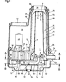
- Fig. 1 einen Vertikalschnitt durch ein Raumheizgerät,
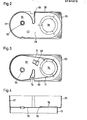
- Fig. 2 einen Horizontalschnitt nach der Linie II-II der Fig. 1,
- Fig. 3 einen Horizontalschnitt nach der Linie III-III der Fig. 1 und
- Fig. 4 einen Vertikalschnitt durch ein Gebläsekammer-Formstück.
- In dem vereinfacht dargestellten Raumheizgerät befindet sind in einer Brennkammer 1 ein nicht näher beschriebener Brenner 2. Ein Flammrohr 3 ist mit seinem Aufsteckende 8 auf diesen Brenner 2 aufgesetzt. Dieses Flammrohr erstreckt sich im Innern eines Wärmetauschers 10 nach oben, wo es mit seiner oberen Austrittsöffnung 5 kurz vor einer Deckenfläche 23 des Wärmetauschers endet. Mittels Stützen 6 ist auf das Flammrohr noch eine Schutzplatte 7 aufgesetzt, die die Wärmetauscher-Deckenfläche 23 vor Überhitzung schützt. Der Wärmetauscher 10, zweckmäßig ein Formstück aus einer Aluminiumlegierung, bildet an seinem offenen Ende durch einen Sockelzylinder 13 einen Ringraum 11. Ein Sockelbund 14 ist noch zur Halterung des Wärmetauschers auf einer Basisplatte 32 ausgebildet. Vom Ringraum 11 führt ein Abgasstutzen 12 für den Abzug der Verbrennungsgase nach außen. Der Wärmetauscher wird beispielsweise von einem Wellenmantel 15 gebildet. Dieser besteht aus gleichmäßig um den Umfang verlaufenden Wellen mit äußeren Wellenbergen 18 und inneren Wellentälern 17. In den von diesen Wellen gebildeten Kanälen strömen die Verbrennungsgase nach dem Austritt aus dem Flammrohr und Umlenkung an der Deckenfläche 23 nach unten, wo sie vom Ringraum 11 aufgenommen und schließlich durch den Abgasstutzen 12 ins Freie abgeführt werden. Die inneren Wellenkanäle sind oben durch Umlenkwände 25 abgeschlossen, die nach außen schräg abfallen und dadurch günstige Umlenkflächen für die Verbrennungsgase bilden. Der vom Sockelzylinder 13 gebildete Ringraum 11 ist nach außen durch die Übergangswände 26 begrenzt. Liegt das Flammrohr, wie im Ausführungsbeispiel gezeigt, direkt an den Innenflächen der Wellentäler 17 an, dann wird vom Flammrohr die Wärme direkt auf den Wärmetauscher übertragen. Andererseits schließt das an den Wellentälern 17 anliegende Flammrohr 3 diese Wellenkanäle voneinander ab, so daß die Verbrennungsgase in eine Vielzahl von Einzelströmen aufgeteilt werden, die in Form von verhältnismäßig schmalen Strömungsschichten nach unten abfallen und dabei von verhältnismäßig großen Heizflächen umgeben sind. Auf diese Weise ergibt sich eine sehr gleichmäßige Verteilung der Verbrennungsgase und damit auch eine gleichmäßige Wärmeabgabe auf den gesamten Umfang des Wärmetauschers. Der Ringraum 11 wirkt hierbei als Sammelraum für die abfallenden Verbrennungsgase und gewährleistet so ihren ungestörten Abzug, auch wenn nur an einer Stelle ein Abgasstutzen vorhanden ist.
- Der Wärmetauscher 10 ist in einem vorbestimmten Abstand von einem Heizraummantel 28 umgeben. Eine Heißluft-Eintrittsöffnung 29 auf der Höhe des Ringraumes 11 ermöglicht einen ausreichenden Luftzutritt, wobei eine geringfügige Erweiterung 31 des Heizraummantels im unteren Bereich für eine gleichmäßige Verteilung der zuströmenden Luft um den Wärmetauscher sorgt. Oberhalb des Wärmetauschers wird der Heizraunmante. zu einer Heißluft-Austrittsöffnung 30 zusammengeführt, aus der die Heißluft entweder direkt in den zu erwärmenden Raum aus-oder in ein Leitungssystem überströmen kann. Der Wärmetauscher und damit der Heizraummantel können auch genau zylindrisch sein. Eine vorbestimmte Konizität, die die Gaskonzentration infolge Abkühlung berücksichtigt und dadurch eine Strömungsverzögerung vermeidet, ist jedoch vorteilhaft.
- Um auch bei engem Heizraum die Heißluftströmung zwischen Wärmetauscher und Heizraummantel 28 zu verbessern und" insbesondere zu verstärken, ist eine Zwangströmung vorgesehen. Zu diesem Zweck schließt sich an die Heißluft-Eintrittsöffnung 29 eine Gebläsekammer 35 an, die unten von einer Abschlußplatte 36, an der Seite von einer spiralförmig verlaufenden Kammerwand 37 und oben von einer Deckplatte 38 begrenzt.ist. In der Deckplatte ist eine Ansaugöffnung 40 ausgebildet, durch die anzuwärmende Heißluft in die Gebläsekammer einströmt, von einem Radialgebläse 42, z.B. in Form eines Walzenrades, verdichtet und durch die Eintrittsöffnung 29 in den Heizraum gedrückt wird. Um einen guten Wirkungsgrad zu erzielen, ist die Gebläsekammer, wie insbesondere Fig. 2 zeigt, im Querschnitt spiralförmig ausgebildet und auch das Radialgebläse selbst ist gegenüber den Wärmetauscher 10 versetzt gelagert, so daß die Kammerwand einen Gebläse- diffusor 43 bildet, der direkt in die ebenfalls zur Seite verschobene Eintrittsöffnung 29 übergeht. Zur Vervollständigung des Spiralgehäuses bildet die Kammerwand eine Einschnürung 45, die auf der Innenseite die Eintrittsöffnung 29 begrenzt, so daß die Heißluft dem Heizraum radial zugeführt und auf diese Weise eine etwa schraubenförmig hochsteigende Heißluftströmung, die sich auf den ganzen Umfang des Heizgerätes gleichmäßig verteilt, eingeleitet wird. Das Gebläse 42 wird durch einen auf der Deckplatte 38 mittels eines Ständers 47 angeflanschten Motors 48 über die Welle 49 angetrieben, die auf der anderen Gebläseseite in einem Lager 50 gelagert ist. Die Abschlußplatte 36 1st zweckmäßig eine Erweiterung der Basisplatte 32, die das Heizgerät und damit den Verbrennungsgasstrom gegenüber der Heißluft sicher abschließt.
- Bei einem Heizgerät der vorbeschriebenen Ausführungsform wird die zu erwärmende Luft ohne besondere Führung aus dem Raum entnommen und durch das Gebläse dem Heizraum zugeführt. Um diese Raumluft bereits vorzuwärmen und zugleich den heißen Heizraummantel 28 zu schützen; ist ein Außenmantel 55 vorgesehen, der den Heizraummantel mit Abstand umgibt und auf der Seite der Eintrittsöffnung 29 um eine Ansaugsammelkammer 56 erweitert, die eine nach oben gerichtete Einlaßöffnung 57 aufweist, so daß die Raumluft sowohl durch diese Öffnung als auch durch einen Ringeinlaß 58, der die Heißluft-Austrittsöffnung 30 des Heizraumes umgibt, einströmen kann. Auf diese Weise wird erreicht, daß dem Heizraun eine bereits merklich vorgewärmte Raumluft zugeführt wird, da insbesondere die durch den Ringeinlaß zuströmende Luft dem Heizraummantel entlangströmt und erst nach ihrer Erwärmung in die Ansaugsammelkammer 56 gelangt, wo sie sich mit der nicht vorgewärmten Raumluft vermischt. Der Außenmantel besteht zweckmäßig aus zwei längsgeteilten Schalen.
- Um dieses Heizgerät unabhängig von der Verbrennungsgasführung in einem Raum aufstellen zu können, setzt sich der Außenmantel 55 bis unter die Abschluß- und Basisplatte 36 fort und bildet mit seinem Aufsetzgehäuse 60 eine untere, in sich geschlossene Frischluftkammer 61. Zweckmäßigerweise ist ihr Einlaß 62 an die Stelle des Abgasstutzens 12 verlegt, den er ringförmig umgibt, so daß auch die dem Brenner zuzuführende Frischluft schon durch den Abgasstutzen vorgewärmt wird. Außerdem ist es dadurch möglich, dieses Heizgerät an einen Wandanschlußkasten mit kombinierter Frischluft- und Abgasöffnung (nicht dargestellt) anzuschließen. Durch die Vorwärmung der Frischluft wird natürlich auch das durch den Abgasstutzen 12 abströmende Verbrennungsgas abgekühlt. Die koaxiale Frischluftzufuhr bringt noch den weiteren Vorteil, daß bei einer Undichtigkeit in der Abgasführung das austretende Gas vom Frischluftstrom aufgenommen und zum Brenner geführt wird, der bei zu starker Anreicherung selbständig erlischt. Insbesondere bei einer längeren Abgasleitung bis zur Raumaußenwand wird so das Rauminnere sicher geschützt. Diese Frischluftkammer kann auch Regel-Organe, wie ein automatisch gq, steuertes Gasventil 63 aufnehmen, das mit einer von einer Gasleitung 64 gespeisten Gasdüse 65 in Verbindung steht. Diese Gasdüse befindet sich in einer Eingangsöffnung eines Mischerrohres 67, das von einer Klemme 68 (Fig. 3) gehalten zum Brenner 2 führt und von einem flexiblen Rohr gebildet ist, dessen gewellte Innenfläche die Vermischung des Gases mit der Erstluft fördert. Die Frischluft kühlt auch das Gasventil und sonstige hier untergebrachte Armaturen.
- Damit die Frischluftzufuhr und damit auch die Verbrennungsgasströmung von den Außenverhältnissen weitgehend unabhängig sind, ist auch in diesem Bereich eine Zwangsführung der Frischluft vorgesehen. Zu diesem Zweck ist im Innern der Frischluftkammer eine Vorkammer 70 ausgebildet, die oben durch die Abschluß- und Basisplatte 36, 32, seitlich durch eine Wand 71 und unten durch eine Bodenplatte 72 begrenzt ist. Eine Einströmöffnung 73 ist abgelegen vom Einlaß 62 und etwa koaxial zur Ansaugöffnung 40 in der Abschlußplatte ausgebildet. Die durch den Einlaß eintretende Frischluft muß daher die Frischluftkammer 61 bis zum anderen Ende durchströmen, bevor sie in die Vorkammer 70 gelangt. Unterstützt wird diese Strömung durch ein in der Vorkammer auf die Einströmöffnung 73 ausgerichtetes Ventilatorrad 75, das die angesaugte Luft an der Gasdüse vorbei als Erstluft in das Mischerrohr 67 und an diesem vorbei als Zweitluft durch einen Basisplattendurchbruch 76 zum Brenner 2 fördert. Das Ventilatorrad ist dabei gleichachsig zum Radialgebläse 42 angeordnet und kann ebenfalls vom Motor 48 angetrieben werden. Die Vorkammerwand 71 ist im Bereich des Ventilatorrades wiederum spiralförmig gegenüber dem Achslager 50 ausgebildet, wobei dieser so gestaltete Druckraum noch durch einen Einsatzkeil 74 (Fig. 3) ergänzt wird.
- Bei diesem Aufbau sind die Gebläsekammer 42 und die Vorkammer 70 durch die gemeinsamen Abschluß- und Basisplatten 36, 32 getrennt und da auch die Gestaltung dieser Kammern weitgehend übereinstimmt, läßt sich durch die Ausbildung eines solchen Formstückes eine wesentliche Vereinfachung im Geräteaufbau und in der Montage erzielen. Dieses Formstück besteht, wie Fig. 4 zeigt, aus der Abschluß- und Basisplatte 36, 32, der davon einseitig abstehenden Gebläsekammerwand 37, die um einen Heizraumsockel 78 erweitert ist, sowie der auf der anderen Seite abstehenden Vorkammerwand 71.
- Die Erfindung ist nicht auf das dargestellte Ausführungsbeispiel beschränkt. So kann der Außenmantel entfallen, wenn auf die Vorwärmung der Umluft verzichtet wird. Die Frischluftkammer und eventuell auch die Vorkammer sind dann nicht unbedingt notwendig, wenn das Gerät derart in einem Raumboden montiert wird, daß die Frischluft ausschließlich von unterhalb dieses Raumbodens zugeführt wird. Andererseits ist auch die Ausbildung der Frischluft- und Vorkammer 61, 70 ohne den Außenmantel 55 möglich. Die höchste Leistung und größten Vorteile bietet das Heizgerät aber mit einem Außenmantel zur Umluft- bzw. Heißluftführung, sowie mit Frischluft- und Vorkammer, wobei zweckmäßigerweise diese Einrichtungen von einem Gehäuse gebildet werden und so ein verhältnismäßig kleines, kompaktes und in dem Raum aufstellbares Heizgerät entsteht.
Claims (13)
Applications Claiming Priority (2)
| Application Number | Priority Date | Filing Date | Title |
|---|---|---|---|
| DE3325344 | 1983-07-13 | ||
| DE19833325344 DE3325344C2 (de) | 1983-07-13 | 1983-07-13 | Raumheizgerät für Kleinräume |
Publications (3)
| Publication Number | Publication Date |
|---|---|
| EP0131872A2 true EP0131872A2 (de) | 1985-01-23 |
| EP0131872A3 EP0131872A3 (en) | 1986-01-08 |
| EP0131872B1 EP0131872B1 (de) | 1987-09-30 |
Family
ID=6203927
Family Applications (1)
| Application Number | Title | Priority Date | Filing Date |
|---|---|---|---|
| EP19840107932 Expired EP0131872B1 (de) | 1983-07-13 | 1984-07-06 | Raumheizgerät für Kleinräume |
Country Status (2)
| Country | Link |
|---|---|
| EP (1) | EP0131872B1 (de) |
| DE (1) | DE3325344C2 (de) |
Cited By (2)
| Publication number | Priority date | Publication date | Assignee | Title |
|---|---|---|---|---|
| EP0271783A3 (en) * | 1986-12-19 | 1988-09-21 | Philipp Kreis Gmbh & Co. Truma-Geratebau | Heater for small spaces, especially for mobile spaces |
| US11046150B2 (en) * | 2017-08-21 | 2021-06-29 | Eberspächer Climate Control Systems GmbH | Vehicle heater |
Families Citing this family (4)
| Publication number | Priority date | Publication date | Assignee | Title |
|---|---|---|---|---|
| AU201712794S (en) | 2016-11-23 | 2017-05-23 | Dometic Sweden Ab | Ventilation and air conditioning apparatus |
| DE112018005883T5 (de) | 2017-11-16 | 2020-07-30 | Dometic Sweden Ab | Klimatisierungsvorrichtung für wohnmobile |
| USD905217S1 (en) | 2018-09-05 | 2020-12-15 | Dometic Sweden Ab | Air conditioning apparatus |
| IT201900019193A1 (it) | 2019-10-17 | 2021-04-17 | Dometic Sweden Ab | Apparato di condizionamento dell'aria per veicoli ricreativi |
Family Cites Families (6)
| Publication number | Priority date | Publication date | Assignee | Title |
|---|---|---|---|---|
| NL43876C (de) * | 1928-01-25 | 1900-01-01 | ||
| US2384836A (en) * | 1941-02-26 | 1945-09-18 | Galvin Mfg Corp | Heater |
| GB876229A (en) * | 1960-03-09 | 1961-08-30 | Webasto Werk Baier Kg W | Improvements in and relating to heating devices operated with liquid fuel |
| DE6604583U (de) * | 1964-01-24 | 1970-01-29 | Bahco Ab | Heizvorrichtung fuer fluechtige brennstoffe, insbesondere zur verwendung in motorfahrzeugen |
| DE2139504C3 (de) * | 1971-08-06 | 1979-06-28 | Fa. J. Eberspaecher, 7300 Esslingen | Heizgerät für mobile Einheiten |
| DE2434450C3 (de) * | 1974-07-17 | 1980-03-13 | Kreis, Philipp, 8000 Muenchen | Raumheizgerät, insbesondere für fahrbare Räume |
-
1983
- 1983-07-13 DE DE19833325344 patent/DE3325344C2/de not_active Expired
-
1984
- 1984-07-06 EP EP19840107932 patent/EP0131872B1/de not_active Expired
Cited By (2)
| Publication number | Priority date | Publication date | Assignee | Title |
|---|---|---|---|---|
| EP0271783A3 (en) * | 1986-12-19 | 1988-09-21 | Philipp Kreis Gmbh & Co. Truma-Geratebau | Heater for small spaces, especially for mobile spaces |
| US11046150B2 (en) * | 2017-08-21 | 2021-06-29 | Eberspächer Climate Control Systems GmbH | Vehicle heater |
Also Published As
| Publication number | Publication date |
|---|---|
| DE3325344C2 (de) | 1986-11-13 |
| DE3325344A1 (de) | 1985-01-24 |
| EP0131872A3 (en) | 1986-01-08 |
| EP0131872B1 (de) | 1987-09-30 |
Similar Documents
| Publication | Publication Date | Title |
|---|---|---|
| DE1476743A1 (de) | Gehaeuse fuer eine Gasturbine und einen elektrischen Generatorsatz | |
| EP0544853B1 (de) | Luftheizgerät | |
| CH633347A5 (de) | Gasturbine. | |
| DE1451413A1 (de) | Tragbarer Raumheizapparat | |
| EP0131872A2 (de) | Raumheizgerät für Kleinräume | |
| DE68922313T2 (de) | Verbrennungsvorrichtung. | |
| EP0128463B1 (de) | Raumheizgerät für Kleinräume | |
| EP3428533B1 (de) | Abgasvorrichtung für eine brenneinrichtung in einem fahrzeug | |
| DE2432850A1 (de) | Heizgeraet fuer fahrzeuge | |
| EP0348646B1 (de) | Brenner | |
| EP0281506A2 (de) | Heizungsanlage mit Vorwärmung der Verbrennungsluft | |
| DE2609987A1 (de) | Brenner fuer kessel mit hohem widerstand | |
| DE2212320A1 (de) | Heizvorrichtung fuer Absorptionskuehler | |
| EP0271783B1 (de) | Raumheizgerät für Kleinräume, insbesondere für fahrbare Räume | |
| EP1970233B1 (de) | Einrichtung zum Konditionieren von in einen Fahrzeuginnenraum einzuleitender Luft | |
| DE2811586A1 (de) | Heizanlage | |
| DE1806519A1 (de) | Verfahren und Vorrichtung zum Aufheizen von Gasen,insbesondere Luft | |
| DE3502648C2 (de) | ||
| DE1558557C3 (de) | Umwälzbackofen | |
| DE19538701C2 (de) | Warmlufterzeuger | |
| DE1679311C3 (de) | Heizkessel für flüssige Wärmeträger | |
| DE735331C (de) | Einrichtung zum Zufuehren von Zweitluft bei Kohlenstaubbrennern | |
| DE4109576A1 (de) | An der wand montierbarer, gegenueber dem raum abgeschlossener gasheizkessel mit geblaese | |
| EP0916907B1 (de) | Mobiles Warmluftgebläse | |
| AT229998B (de) | Ölbrenneraggregat |
Legal Events
| Date | Code | Title | Description |
|---|---|---|---|
| PUAI | Public reference made under article 153(3) epc to a published international application that has entered the european phase |
Free format text: ORIGINAL CODE: 0009012 |
|
| AK | Designated contracting states |
Designated state(s): BE FR GB IT NL SE |
|
| PUAL | Search report despatched |
Free format text: ORIGINAL CODE: 0009013 |
|
| AK | Designated contracting states |
Designated state(s): BE FR GB IT NL SE |
|
| 17P | Request for examination filed |
Effective date: 19851204 |
|
| 17Q | First examination report despatched |
Effective date: 19860520 |
|
| GRAA | (expected) grant |
Free format text: ORIGINAL CODE: 0009210 |
|
| AK | Designated contracting states |
Kind code of ref document: B1 Designated state(s): BE FR GB IT NL SE |
|
| ITF | It: translation for a ep patent filed | ||
| ET | Fr: translation filed | ||
| GBT | Gb: translation of ep patent filed (gb section 77(6)(a)/1977) | ||
| PLBE | No opposition filed within time limit |
Free format text: ORIGINAL CODE: 0009261 |
|
| STAA | Information on the status of an ep patent application or granted ep patent |
Free format text: STATUS: NO OPPOSITION FILED WITHIN TIME LIMIT |
|
| 26N | No opposition filed | ||
| ITTA | It: last paid annual fee | ||
| PGFP | Annual fee paid to national office [announced via postgrant information from national office to epo] |
Ref country code: GB Payment date: 19930701 Year of fee payment: 10 |
|
| PGFP | Annual fee paid to national office [announced via postgrant information from national office to epo] |
Ref country code: SE Payment date: 19930728 Year of fee payment: 10 Ref country code: FR Payment date: 19930728 Year of fee payment: 10 |
|
| PGFP | Annual fee paid to national office [announced via postgrant information from national office to epo] |
Ref country code: NL Payment date: 19930731 Year of fee payment: 10 |
|
| PGFP | Annual fee paid to national office [announced via postgrant information from national office to epo] |
Ref country code: BE Payment date: 19930805 Year of fee payment: 10 |
|
| PG25 | Lapsed in a contracting state [announced via postgrant information from national office to epo] |
Ref country code: GB Effective date: 19940706 |
|
| PG25 | Lapsed in a contracting state [announced via postgrant information from national office to epo] |
Ref country code: SE Effective date: 19940707 |
|
| PG25 | Lapsed in a contracting state [announced via postgrant information from national office to epo] |
Ref country code: BE Effective date: 19940731 |
|
| BERE | Be: lapsed |
Owner name: PHILIPP KREIS G.M.B.H. & CO. TRUMA-GERATEBAU Effective date: 19940731 |
|
| EUG | Se: european patent has lapsed |
Ref document number: 84107932.0 Effective date: 19950210 |
|
| PG25 | Lapsed in a contracting state [announced via postgrant information from national office to epo] |
Ref country code: NL Effective date: 19950201 |
|
| GBPC | Gb: european patent ceased through non-payment of renewal fee |
Effective date: 19940706 |
|
| NLV4 | Nl: lapsed or anulled due to non-payment of the annual fee | ||
| PG25 | Lapsed in a contracting state [announced via postgrant information from national office to epo] |
Ref country code: FR Effective date: 19950331 |
|
| EUG | Se: european patent has lapsed |
Ref document number: 84107932.0 |
|
| REG | Reference to a national code |
Ref country code: FR Ref legal event code: ST |