EP0131786B1 - Wickelkörper - Google Patents
Wickelkörper Download PDFInfo
- Publication number
- EP0131786B1 EP0131786B1 EP84107225A EP84107225A EP0131786B1 EP 0131786 B1 EP0131786 B1 EP 0131786B1 EP 84107225 A EP84107225 A EP 84107225A EP 84107225 A EP84107225 A EP 84107225A EP 0131786 B1 EP0131786 B1 EP 0131786B1
- Authority
- EP
- European Patent Office
- Prior art keywords
- winding
- package according
- band
- tape
- winding layers
- Prior art date
- Legal status (The legal status is an assumption and is not a legal conclusion. Google has not performed a legal analysis and makes no representation as to the accuracy of the status listed.)
- Expired
Links
- 238000004804 winding Methods 0.000 claims description 71
- 239000000853 adhesive Substances 0.000 claims description 3
- 230000001070 adhesive effect Effects 0.000 claims description 3
- 239000002904 solvent Substances 0.000 claims description 2
- 239000000463 material Substances 0.000 description 3
- 238000000034 method Methods 0.000 description 3
- 239000002318 adhesion promoter Substances 0.000 description 2
- 238000004519 manufacturing process Methods 0.000 description 2
- 239000004033 plastic Substances 0.000 description 2
- 230000002787 reinforcement Effects 0.000 description 2
- 238000003860 storage Methods 0.000 description 2
- 238000004026 adhesive bonding Methods 0.000 description 1
- 239000002131 composite material Substances 0.000 description 1
- 230000006378 damage Effects 0.000 description 1
- 238000003912 environmental pollution Methods 0.000 description 1
- 239000003000 extruded plastic Substances 0.000 description 1
- 239000007788 liquid Substances 0.000 description 1
- 238000004806 packaging method and process Methods 0.000 description 1
- 238000012856 packing Methods 0.000 description 1
- 230000003014 reinforcing effect Effects 0.000 description 1
- 229920006395 saturated elastomer Polymers 0.000 description 1
- 239000004753 textile Substances 0.000 description 1
Images


Classifications
-
- B—PERFORMING OPERATIONS; TRANSPORTING
- B65—CONVEYING; PACKING; STORING; HANDLING THIN OR FILAMENTARY MATERIAL
- B65H—HANDLING THIN OR FILAMENTARY MATERIAL, e.g. SHEETS, WEBS, CABLES
- B65H75/00—Storing webs, tapes, or filamentary material, e.g. on reels
-
- B—PERFORMING OPERATIONS; TRANSPORTING
- B65—CONVEYING; PACKING; STORING; HANDLING THIN OR FILAMENTARY MATERIAL
- B65H—HANDLING THIN OR FILAMENTARY MATERIAL, e.g. SHEETS, WEBS, CABLES
- B65H55/00—Wound packages of filamentary material
-
- B—PERFORMING OPERATIONS; TRANSPORTING
- B65—CONVEYING; PACKING; STORING; HANDLING THIN OR FILAMENTARY MATERIAL
- B65H—HANDLING THIN OR FILAMENTARY MATERIAL, e.g. SHEETS, WEBS, CABLES
- B65H2701/00—Handled material; Storage means
- B65H2701/30—Handled filamentary material
- B65H2701/37—Tapes
-
- Y—GENERAL TAGGING OF NEW TECHNOLOGICAL DEVELOPMENTS; GENERAL TAGGING OF CROSS-SECTIONAL TECHNOLOGIES SPANNING OVER SEVERAL SECTIONS OF THE IPC; TECHNICAL SUBJECTS COVERED BY FORMER USPC CROSS-REFERENCE ART COLLECTIONS [XRACs] AND DIGESTS
- Y10—TECHNICAL SUBJECTS COVERED BY FORMER USPC
- Y10S—TECHNICAL SUBJECTS COVERED BY FORMER USPC CROSS-REFERENCE ART COLLECTIONS [XRACs] AND DIGESTS
- Y10S242/00—Winding, tensioning, or guiding
- Y10S242/02—Narrow fabric winding apparatus
Definitions
- the invention relates to a winding body with a wound tape according to the preamble of claim 1.
- Winding bodies of the type mentioned at the outset are known and are produced by winding plastic tapes onto a support body, such as a sleeve, after extruding, stretching and, if appropriate, fixing the tape. They are used for the orderly handling of the tape from its production to its use.
- the support body of the winding body performs several individual functions: it enables the structure of the winding body, its removal from the winding mandrel, the subsequent storage, the application to a dispensing element and the removal, always while maintaining the given winding order. In order to fulfill all of these individual functions, especially to withstand the pressure of the wound tape, the support body must have sufficient strength.
- this support body require a non-production effort from the manufacturer of the belt.
- the empty support body is then removed, which removes and eliminates, e.g. must be burned.
- the object of the present invention is to provide a winding body of the type mentioned at the outset, the supporting body of which does not have to be manipulated on its own before the tape is wound up.
- the manufacturer of the winding body according to the invention does not have to purchase, store and present the element of the winding body that was previously unrelated to the industry, and its removal and destruction by the consumer, which means both economical savings and a reduction in environmental pollution.
- winding body according to the invention formed by parallel windings is dimensionally stable without a one-piece, stable external supporting body, all the more so since external supporting bodies with insufficient strength are deformed in the known winding bodies.
- the dimensional stability of the winding body according to the invention is based on an equilibrium between the pressure of the individual windings or the winding layers on the support body and on the internal stress of the winding layers of the support body.
- the individual turns of the support body act, d. H. the inner winding layers, in the manner of a central reinforcement.
- the winding body according to the invention can not only be used on tape unwinders like the known winding bodies, but also as a dispenser roll, i. H. the tape can be drawn off both from the circumference and from the center of the winding body.
- This universal usability brings additional savings, since the same winding body can be used both by the large consumer who has a tape unwinding device and by the small consumer who takes out the tape manually.
- the winding body according to the invention is produced according to known methods by winding up the tape, a winding mandrel or cylinder belonging to the winding device being used instead of the coil.
- the beginning of the tape is fixed to the winding mandrel or cylinder by gluing or constructive measures.
- the tension of the tape or the torque of the winding during the winding process can be controlled by known, possibly electronic means.
- extruded plastic bands as in the case of the known wrap having an external support body, it is not a saturated but a relationship moderately loose winding created to allow the tape to shrink without deforming the winding.
- the band can also be pretreated in this area to bring the coils adjacent to the axial opening to a stronger adhesion.
- a stronger adhesion can be achieved by applying an adhesion promoter or by increasing the self-adhesion by means of solvent or heat.
- Known, preferably liquid, adhesives are suitable as adhesion promoters.
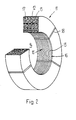
- the known winding body 1 in FIG. 1 has a tape 3 wound in a parallel winding 2. In the middle of a continuous axial opening 4 is arranged, which is supported by a support body 5, z. B. of cardboard, is limited and to which the innermost or first winding layer of the winding body 1 is applied.
- the winding bodies 11 according to the invention in FIGS. 2 and 3 also have a tape 13 wound in a parallel winding 12. Their continuous axial openings 14 are each delimited by the innermost or first winding layer 16, which together with the subsequent winding layers 17 can be regarded as a support body 15. The adhesion of these inner winding layers 16, 17 to one another is reinforced in FIG. 3 by an adhesive.
- the windings 12 of the winding body 11 in FIG. 2 are strapped with three packaging tapes 18 in order to enable the winding body 11 to be transported without problems.
- the winding body according to the invention can be made of flexible tapes of various types, for. B. textile materials, composite materials and preferably made of plastic tapes with a smooth or structured surface. Since the support body also consists of these flexible materials, the winding bodies according to the invention have increased elasticity compared to the known winding bodies with a rigid external support body.
- winding bodies according to the invention not only result in a saving of material from outside the industry and ecological advantages, but also make it possible to dispense with the logistics required for the procurement of the external support bodies.
Landscapes
- Storage Of Web-Like Or Filamentary Materials (AREA)
- Packaging Of Annular Or Rod-Shaped Articles, Wearing Apparel, Cassettes, Or The Like (AREA)
- Packaging Of Machine Parts And Wound Products (AREA)
Description
- Die Erfindung betrifft einen Wickelkörper mit einem aufgewickelten Band gemäss dem Oberbegriff des Anspruches 1.
- Wickelkörper der eingangs genannten Art sind bekannt und werden durch Aufwickeln von Kunststoffbändern auf einen Stützkörper, wie eine Hülse, nach dem Extrudieren, Strecken und gegebenenfalls Fixieren des Bandes hergestellt. Sie dienen zur geordneten Handhabung des Bandes von dessen Herstellung an bis zu dessen Verwendung. Der Stützkörper des Wickelkörpers übt dabei mehrere Einzelfunktionen aus : er ermöglicht den Aufbau des Wickelkörpers, seine Entfernung vom Wickeldorn, die nachfolgende Lagerung, das Aufbringen auf ein Abgabeorgan und die Entnahme, immer unter Aufrechterhaltung der gegebenen Wickelordnung. Um alle diese Einzelfunktionen zu erfüllen, vor allem um dem Druck des aufgewickelten Bandes standzuhalten, muss der Stützkörper eine genügende Festigkeit aufweisen.
- Die Anschaffung, Lagerung und das jeweilige Vorlegen dieses Stützkörpers erfordert vom Hersteller des Bandes einen produktionsfremden Aufwand. Beim Verbraucher des Bandes fällt dann der leere Stützkörper an, der entfernt und beseitigt, z.,B. verbrannt, werden muss.
- Aus der DE-A-25 32 611 ist eine trägerlose Kreuzwicklung für Fäden bekannt, die zur Erzielung der erforderlichen Festigkeit mit einer äusseren Umhüllung oder mit zusätzlichen Fadenwicklungen versehen ist. Der Faden aus einer solchen Kreuzwicklung kann nur aus ihrem Zentrum abgezogen werden.
- Aufgabe der vorliegenden Erfindung ist es, einen Wickelkörper der eingangs genannten Art zu schaffen, dessen Stützkörper vor dem Aufwickeln des Bandes nicht für sich allein manipuliert werden muss.
- Die. gestellte Aufgabe wird erfindungsgemäss durch das Merkmal des kennzeichnenden Teils des Anspruches 1 gelöst.
- Da der erfindungsgemässe Wickelkörper keinen fremden Stützkörper besitzt, entfallen beim Hersteller des erfindungsgemässen Wickelkörpers die Anschaffung, Lagerung und das Vorlegen des bisher branchenfremden Elementes des Wickelkörpers und beim Verbraucher seine Entfernung und Vernichtung, was sowohl eine wirtschaftliche Einsparung als auch eine Verminderung der Umweltbelastung bedeutet.
- Es ist ausserordentlich überraschend, dass der erfindungsgemässe von Parallelwicklungen gebildete Wickelkörper ohne einstückigen stabilen Fremdstützkörper formbeständig ist, umso mehr, als Fremdstützkörper mit ungenügender Festigkeit in den bekannten Wickelkörpern deformiert werden.
- Es wird vermutet, dass die Formbeständigkeit des erfindungsgemässen Wickelkörpers auf einem Gleichgewicht zwischen dem Druck der einzelnen Windungen bzw. den Windungsschichten auf den Stützkörper und auf der Eigenspannung der Windungsschichten des Stützkörpers beruht. Im Ruhezustand, d. h. ohne äussere Krafteinwirkung, wirken die einzelnen Windungen des Stützkörpers, d. h. der inneren Windungsschichten, in der Art einer zentralen Armierung. Zusätzlich ergibt sich an den Kreuzungspunkten der aufeinanderliegenden Windungen mit entgegengesetzter Steigung ein Raumgitter, das die räumliche Stabilität in der Art einer räumlichen Armierung und den Druckausgleich im Wickelkörper sichert.
- Das oben erwähnte Gleichgewicht bleibt auch während des Entfernens des fertiggestellten Wickelkörpers von einem Wickeldorn erhalten. Dabei wird durch die angreifenden achsenparallelen Kräfte der Wickelkörper von einem Passsitz in einen Schiebesitz, unter geringfügiger Aufweitung der axialen Oeffnung und entsprechender Verformung des Stützkörpers, übergeführt. Die Verformung bei der Aufweitung bewirkt eine Verkleinerung des Steigungswinkels der Windungen, d. h. deren Aufrichten auf den Achsennormalen zu. Durch die Aufweitung und dieses Aufrichten wird der vom Stützkörper nach aussen ausgeübte Druck und damit die Armierwirkung, verstärkt, was die Formbeständigkeit des Wickelkörpers, trotz an ihm während der Entfernung vom Wickeldorn angreifender Kräften, sichert.
- Der gleiche Vorgang findet beim Aufschieben des Wickelkörpers auf den Spreizkern eines Bandabrollers statt, bei dem axiale Schiebekräfte am Wickelkörper angreifen. Nach Beendigung der Krafteinwirkung sowohl beim Abziehen als auch beim Aufschieben, kehren die Windungen in ihre ursprüngliche Lage zurück und sichern dort die Stabilität des Wickelkörpers im Ruhezustand.
- Da er keinen Fremdstützkörper aufweist, kann der erfindungsgemässe Wickelkörper nicht nur wie die bekannten Wickelkörper auf Bandabrollern, sondern auch als Dispenserrolle eingesetzt werden, d. h. das Band kann sowohl vom Umfang als auch vom Zentrum des Wickelkörpers abgezogen werden. Diese universelle Verwendbarkeit bringt eine zusätzliche Einsparung, da derselbe Wickelkörper sowohl vom Grossverbraucher, der über eine Bandabrollreinrichtung verfügt, als auch vom Kleinverbraucher, der die Bandentnahme manuell vornimmt, verwendet werden kann.
- Der erfindungsgemässe Wickelkörper wird nach bekannten Verfahren durch Aufwickeln des Bandes, wobei anstelle der Spule ein zur Wickeleinrichtung gehörender Wickeldorn oder -zylinder verwendet wird, hergestellt. Die Fixierung des Bandanfanges am Wickeldorn oder -zylinder erfolgt durch Kleben oder konstruktive Massnahmen. Die Spannung des Bandes bzw. der Drehmoment des Wickels während des Aufwickelvorganges kann mit bekannten, gegebenenfalls elektronischen Mitteln, gesteuert werden. Dabei wird mit extrudierten Kunststoffbändern, wie auch beim bekannten, einen Fremdstützkörper aufweisenden Wickel, keine satte, sondern eine verhältnismässig lockere Wicklung erstellt, um eine Nachschrumpfung des Bandes ohne Verformung des Wickels zu ermöglichen.
- Zur Herbeiführung eines stärkeren Aneinanderhaftens der an die axiale Oeffnung angrenzenden Wicklungen kann das Band in diesem Bereich auch vorbehandelt werden. Ein stärkeres Aneinanderhaften kann durch Aufbringen eines Haftvermittlers oder durch Erhöhung der Eigenhaftung mittels Lösungsmittel oder Wärme erzielt werden. Als Haftvermittler kommen bekannte, vorzugsweise flüssige, Klebstoffe in Frage.
- Nach dem Aufwickeln des Bandes, d. h. nach der Fertigstellung des Wickelkörpers, kann das Bandende gegen das Abwickeln fixiert werden und der Wickelkörper kann wie üblich mit einem Packband für den Transport versehen werden. Der erfindungsgemässe Wickelkörper wird anhand der Figuren näher veranschlaulicht. Es zeigen rein schematisch und teilweise im Schnitt :
- Fig. 1 die perspektivische Ansicht eines Wickelkörpers gemäss dem Stand der Technik ;
- Fig. 2 die perspektivische Ansicht eines Wickelkörpers gemäss der Erfindung ; und
- Fig. 3 die perspektivische Ansicht eines weiteren Wickelkörpers gemäss der Erfindung.
- Der bekannte Wickelkörper 1 in Fig. 1 weist ein in Parallelwicklung 2 aufgewickeltes Band 3 auf. In seiner Mitte ist eine durchgehende axiale Oeffnung 4 angeordnet, die von einem Stützkörper 5, z. B. aus Karton, begrenzt ist und an den die innerste oder erste Windungsschicht des Wickelkörpers 1 anliegt.
- Die erfindungsgemässen Wickelkörper 11 in den Fig. 2 und 3 weisen auch ein in Parallelwicklung 12 aufgewickeltes Band 13 auf. Ihre durchgehenden axialen Oeffnungen 14 sind jeweils von der innersten oder ersten Windungsschicht 16 begrenzt, die zusammen mit den anschliessenden Windungsschichten 17 als Stützkörper 15 betrachtet werden können. Die Haftung dieser inneren Windungsschichten 16, 17 aneinander ist in Fig. 3 durch einen Klebstoff verstärkt.
- Die Wicklungen 12 des Wickelkörpers 11 in Fig. 2 sind mit drei Verpackungsbändern 18 umreift, um den problemlosen Transport des Wickelkörpers 11 zu ermöglichen.
- Die erfindungsgemässen Wickelkörper können aus biegsamen Bändern verschiedenster Art, z. B. Textilmaterialien, Verbundmaterialien und vorzugsweise aus Kunststoffbändern mit glatter oder strukturierter Oberfläche, hergestellt werden. Da der Stützkörper auch aus diesen biegsamen Materialien besteht, weisen die erfindungsgemässen Wickelkörper gegenüber den bekannten Wickelkörpern mit starrem Fremdstützkörper eine erhöhte Elastizität auf.
- Die erfindungsgemässen Wickelkörper bewirken nicht nur eine Einsparung an branchenfremdem Material und ökologische Vorteile, sondern ermöglichen den Verzicht auf die für die Beschaffung der Fremdstützkörper erforderlichen Logistik.
Claims (10)
Applications Claiming Priority (2)
| Application Number | Priority Date | Filing Date | Title |
|---|---|---|---|
| CH393983 | 1983-07-19 | ||
| CH3939/83 | 1983-07-19 |
Publications (2)
| Publication Number | Publication Date |
|---|---|
| EP0131786A1 EP0131786A1 (de) | 1985-01-23 |
| EP0131786B1 true EP0131786B1 (de) | 1989-04-26 |
Family
ID=4266734
Family Applications (1)
| Application Number | Title | Priority Date | Filing Date |
|---|---|---|---|
| EP84107225A Expired EP0131786B1 (de) | 1983-07-19 | 1984-06-23 | Wickelkörper |
Country Status (5)
| Country | Link |
|---|---|
| US (1) | US4533046A (de) |
| EP (1) | EP0131786B1 (de) |
| JP (1) | JPS6040379A (de) |
| DE (1) | DE3477918D1 (de) |
| FI (1) | FI75548C (de) |
Families Citing this family (9)
| Publication number | Priority date | Publication date | Assignee | Title |
|---|---|---|---|---|
| US5105599A (en) | 1989-02-24 | 1992-04-21 | Highland Supply Corporation | Means for securing a decorative cover about a flower pot |
| US5339601A (en) * | 1991-05-03 | 1994-08-23 | Highland Supply Corporation | Decorative cover with band |
| US5426914A (en) * | 1989-02-24 | 1995-06-27 | Highland Supply Corporation | Band applicator for applying a band about a sheet of material and a pot |
| US5410856A (en) * | 1988-09-26 | 1995-05-02 | Highland Supply Corporation | Decorative assembly for a floral grouping |
| US6668521B1 (en) * | 1989-02-24 | 2003-12-30 | Southpac Trust International, Inc. | Method for applying a band about a sheet of material and a floral grouping |
| US5617702A (en) * | 1989-02-24 | 1997-04-08 | Southpac Trust International, Inc. | Method for securing a decorative cover about a flower pot |
| DE19823402C1 (de) * | 1998-05-26 | 2000-02-17 | Signode Bernpak Gmbh | Materialwickel, insbesondere Umreifungsmittelwickel für Material zum Umreifen von Packstücken, sowie Verfahren zu seiner Erzeugung |
| KR20000016989A (ko) * | 1998-08-07 | 2000-03-25 | 마스다 야스오 | 포장용 끈코일 및 그 제조방법과, 포장용 끈코일 장치와, 끈코일 감개를 갖춘 포장기계 |
| US6358586B1 (en) * | 1998-08-07 | 2002-03-19 | Sekisui Jushi Kabushiki Kaisha | Packaging strap coil and method for producing the same, packaging strap coil unit and packaging machine equipped with strap coil reel |
Family Cites Families (4)
| Publication number | Priority date | Publication date | Assignee | Title |
|---|---|---|---|---|
| US610339A (en) * | 1898-09-06 | Telegraph-tape | ||
| US1880448A (en) * | 1928-10-09 | 1932-10-04 | Eastman Kodak Co | Core for motion picture films |
| DE2532611C3 (de) * | 1975-07-22 | 1978-09-07 | Faehrenkaemper Gmbh & Co Kg Geraetebau, 4972 Loehne | Wickel aus einem fadenförmigen Material zur Verwendung als Fadenvorrat in Bindemaschinen |
| JPS5836153B2 (ja) * | 1978-08-01 | 1983-08-06 | 明 池口 | コンクリ−ト用型枠の位置決め金具 |
-
1984
- 1984-06-23 DE DE8484107225T patent/DE3477918D1/de not_active Expired
- 1984-06-23 EP EP84107225A patent/EP0131786B1/de not_active Expired
- 1984-06-25 US US06/624,147 patent/US4533046A/en not_active Expired - Fee Related
- 1984-07-12 JP JP59145201A patent/JPS6040379A/ja active Pending
- 1984-07-16 FI FI842858A patent/FI75548C/fi not_active IP Right Cessation
Also Published As
| Publication number | Publication date |
|---|---|
| DE3477918D1 (en) | 1989-06-01 |
| US4533046A (en) | 1985-08-06 |
| FI842858A0 (fi) | 1984-07-16 |
| FI842858L (fi) | 1985-01-20 |
| JPS6040379A (ja) | 1985-03-02 |
| FI75548C (fi) | 1988-07-11 |
| EP0131786A1 (de) | 1985-01-23 |
| FI75548B (fi) | 1988-03-31 |
Similar Documents
| Publication | Publication Date | Title |
|---|---|---|
| DE3227166C1 (de) | Verfahren zur Herstellung eines verstaerkten Schlauches | |
| EP0334211B1 (de) | Verfahren zur Herstellung eines spulenlosen Gebindes | |
| DE2747423C2 (de) | ||
| DE69328313T2 (de) | Rohrförmiger kernaufbau für rollen aus papier oder anderem flachem material | |
| EP0131786A1 (de) | Wickelkörper | |
| CH549523A (de) | Huelse mit uebereinandergewickelten bahnen aus pappe. | |
| DE2106258C3 (de) | Verfahren zum Wickeln einer Übertragerspule und Vorrichtung zur Durchführung dieses Verfahrens | |
| DE3878469T2 (de) | Wulstkern. | |
| DE19823402C1 (de) | Materialwickel, insbesondere Umreifungsmittelwickel für Material zum Umreifen von Packstücken, sowie Verfahren zu seiner Erzeugung | |
| DE3120688C2 (de) | Verfahren zum wendelförmigen Verformen eines Druckträgers, insbesondere in Form eines Drahts für einen Hochdruckschlauch, sowie Vorrichtung zur Durchführung des Verfahrens | |
| DE1928269A1 (de) | Verfahren zur Herstellung von Stuetzelementen aus verstaerktem chemischen Werkstoff und nach dem Verfahren hergestelltes Stuetzelement | |
| DE7936385U1 (de) | Spulenaufbau aus Klebstoffstrang im festem Zustand | |
| EP0017186B1 (de) | Zerlegbare Spule für strangförmiges Gut, insbes. Draht, und Verfahren zum Aufbringen eines Wickels aus strangförmigem Gut auf eine solche Spule | |
| DE3101424A1 (de) | "verfahren zur verarbeitung von laenglichem schlauchmaterial und einrichtung zur durchfuehrung dieses verfahrens" | |
| DE4221574C2 (de) | Wickelkern | |
| DE2532611C3 (de) | Wickel aus einem fadenförmigen Material zur Verwendung als Fadenvorrat in Bindemaschinen | |
| DE60110259T2 (de) | System zum aufwickeln von bandmaterial aus aluminium und zugehörige methode | |
| EP0399488B1 (de) | Hülsenförmiger Wickelkern für dünnes bahnförmiges Wickelgut | |
| EP0170094B2 (de) | Hülse als Wickelkern | |
| DE2410900B2 (de) | Spulenhalter fuer lagenweises aufspulen von draht | |
| DE102019211604A1 (de) | Verfahren zur Herstellung eines Balgrohlings und eine Luftfeder | |
| DE2843200C2 (de) | Anordnung an Transformatoren und Drosselspulen | |
| DE224138C (de) | ||
| DE1914891C (de) | Handhabungseinheit für bahnförmiges, textiles Gut mit empfindlicher Oberfläche | |
| DE851393C (de) | Umhuellungen fuer ringfoermige Fadenwickel |
Legal Events
| Date | Code | Title | Description |
|---|---|---|---|
| PUAI | Public reference made under article 153(3) epc to a published international application that has entered the european phase |
Free format text: ORIGINAL CODE: 0009012 |
|
| AK | Designated contracting states |
Designated state(s): BE CH DE FR GB LI NL SE |
|
| 17P | Request for examination filed |
Effective date: 19850124 |
|
| GRAA | (expected) grant |
Free format text: ORIGINAL CODE: 0009210 |
|
| AK | Designated contracting states |
Kind code of ref document: B1 Designated state(s): BE CH DE FR GB LI NL SE |
|
| REF | Corresponds to: |
Ref document number: 3477918 Country of ref document: DE Date of ref document: 19890601 |
|
| ET | Fr: translation filed | ||
| GBT | Gb: translation of ep patent filed (gb section 77(6)(a)/1977) | ||
| PLBE | No opposition filed within time limit |
Free format text: ORIGINAL CODE: 0009261 |
|
| STAA | Information on the status of an ep patent application or granted ep patent |
Free format text: STATUS: NO OPPOSITION FILED WITHIN TIME LIMIT |
|
| 26N | No opposition filed | ||
| PGFP | Annual fee paid to national office [announced via postgrant information from national office to epo] |
Ref country code: BE Payment date: 19920518 Year of fee payment: 9 |
|
| PGFP | Annual fee paid to national office [announced via postgrant information from national office to epo] |
Ref country code: SE Payment date: 19920525 Year of fee payment: 9 |
|
| PGFP | Annual fee paid to national office [announced via postgrant information from national office to epo] |
Ref country code: GB Payment date: 19930512 Year of fee payment: 10 Ref country code: DE Payment date: 19930512 Year of fee payment: 10 |
|
| PGFP | Annual fee paid to national office [announced via postgrant information from national office to epo] |
Ref country code: FR Payment date: 19930519 Year of fee payment: 10 |
|
| PG25 | Lapsed in a contracting state [announced via postgrant information from national office to epo] |
Ref country code: SE Effective date: 19930624 |
|
| PGFP | Annual fee paid to national office [announced via postgrant information from national office to epo] |
Ref country code: CH Payment date: 19930628 Year of fee payment: 10 |
|
| PG25 | Lapsed in a contracting state [announced via postgrant information from national office to epo] |
Ref country code: BE Effective date: 19930630 |
|
| PGFP | Annual fee paid to national office [announced via postgrant information from national office to epo] |
Ref country code: NL Payment date: 19930630 Year of fee payment: 10 |
|
| BERE | Be: lapsed |
Owner name: STRAPEX A.G. Effective date: 19930630 |
|
| PG25 | Lapsed in a contracting state [announced via postgrant information from national office to epo] |
Ref country code: GB Effective date: 19940623 |
|
| PG25 | Lapsed in a contracting state [announced via postgrant information from national office to epo] |
Ref country code: LI Effective date: 19940630 Ref country code: CH Effective date: 19940630 |
|
| PG25 | Lapsed in a contracting state [announced via postgrant information from national office to epo] |
Ref country code: NL Effective date: 19950101 |
|
| EUG | Se: european patent has lapsed |
Ref document number: 84107225.9 Effective date: 19940110 |
|
| NLV4 | Nl: lapsed or anulled due to non-payment of the annual fee | ||
| GBPC | Gb: european patent ceased through non-payment of renewal fee |
Effective date: 19940623 |
|
| PG25 | Lapsed in a contracting state [announced via postgrant information from national office to epo] |
Ref country code: FR Effective date: 19950228 |
|
| REG | Reference to a national code |
Ref country code: CH Ref legal event code: PL |
|
| PG25 | Lapsed in a contracting state [announced via postgrant information from national office to epo] |
Ref country code: DE Effective date: 19950301 |
|
| REG | Reference to a national code |
Ref country code: FR Ref legal event code: ST |