EP0130707B1 - Appareil respiratoire - Google Patents
Appareil respiratoire Download PDFInfo
- Publication number
- EP0130707B1 EP0130707B1 EP84303822A EP84303822A EP0130707B1 EP 0130707 B1 EP0130707 B1 EP 0130707B1 EP 84303822 A EP84303822 A EP 84303822A EP 84303822 A EP84303822 A EP 84303822A EP 0130707 B1 EP0130707 B1 EP 0130707B1
- Authority
- EP
- European Patent Office
- Prior art keywords
- facepiece
- inlet
- respirator
- pump
- pump means
- Prior art date
- Legal status (The legal status is an assumption and is not a legal conclusion. Google has not performed a legal analysis and makes no representation as to the accuracy of the status listed.)
- Expired
Links
Images


Classifications
-
- A—HUMAN NECESSITIES
- A62—LIFE-SAVING; FIRE-FIGHTING
- A62B—DEVICES, APPARATUS OR METHODS FOR LIFE-SAVING
- A62B18/00—Breathing masks or helmets, e.g. affording protection against chemical agents or for use at high altitudes or incorporating a pump or compressor for reducing the inhalation effort
- A62B18/006—Breathing masks or helmets, e.g. affording protection against chemical agents or for use at high altitudes or incorporating a pump or compressor for reducing the inhalation effort with pumps for forced ventilation
Definitions
- the present invention relates to breathing apparatus of the type known as power respirators or power-assisted respirators in which filtered air is pumped to a facepiece covering at least the mouth of the wearer to ensure a supply of clean breathable air in a dusty or otherwise contaminated environment.
- the main benefit to the wearer of using a powered respirator is that his lungs are relieved of the slight strain caused by inhalation against the resistance of the filters which, in a conventional non-powered respirator, are attached directly to the facepiece.
- the powered respirator by delivering a steady stream of air to the facepiece usually maintains a slight positive pressure within the facepiece, as determined by the resistance of an exhale valve, thus ensuring that leakage due to a badly fitting facepiece is outward rather than inward.
- Such a powered respirator has been used extensively for the filtration of hazardous dusts, e.g. asbestos, where the high-efficiency filters required by this hazard would otherwise impose an unacceptable inhalation strain on the wearer, particularly during heavy exertion involved in asbestos stripping operations.
- hazardous dusts e.g. asbestos
- a power assisted respirator comprising a facepiece for covering at least the mouth and nose of the wearer and having an inlet and an outlet for air, one-way exhale valve means in the outlet which is operable to permit air to flow out of the space within the facepiece when a predetermined differential pressure is established thereacross, pump means for supplying air to the space within the facepiece and having inlet means for air, power means connected to the pump means for energising the pump means, one-way inlet valve means in the path of airflowing from the pump means to the space within the facepiece permitting air to flow to the said space, the operating parameters of the pump means, the exhale valve means and the inlet valve means being selected so that, during exhalation by the wearer, the inlet valve means will close and the pump means will be placed in a condition in which it will cease or substantially cease to operate effectively, although continuing to run, and filter means connected to the pump means inlet means for filtering air supplied thereto.
- GB 2032284 describes a power assisted respirator in which the pump is controlled in dependence on the output of a pressure sensor sensing the pressure within the facepiece with a view to reducing the pump output during exhalation to thereby extend filter life.
- the output of the pump can be reduced by reducing the power supplied to the pump and this also has the effect of extending battery life for a battery operated pump.
- a power assisted respirator comprising a facepiece for covering at least the mouth and nose of the wearer and having an inlet and an outlet for air, one-way exhale valve means in the outlet which is operable to permit air to flow out of the space within the facepiece when a predetermined differential pressure is established thereacross, pump means for supplying air to the space within the facepiece and having inlet means for air, power means connected to the pump means for energising the pump means, one-way inlet valve means in the path of air flowing from the pump means to the space within the facepiece permitting air to flow to the said space, the operating parameters of the pump means, the exhale valve means and the inlet valve means being selected so that, during exhalation by the wearer, the inlet valve means will close and the pump means will be placed in a condition in which it will cease or substantially cease to operate effectively although continuing to run, and filter means connected to the pump means inlet means for filtering air supplied thereto, wherein a pressure sensor is provided for sensing the pressure
- the exhale valve is arranged to open when the pressure within the facepiece exceeds a predetermined pressure P, for example in the range 150 to 600 Pascals above atmospheric pressure.
- the pump is arranged so that it will cease or substantially cease to operate effectively, i.e. so that, although the fan continues to rotate, no or substantially no air is driven thereby, when the pressure downstream of the pump and upstream of the inlet valve is slightly less than the predetermined pressure P.
- the pressure within the facepiece will increase towards the pressure P and at the point when the pressure within the facepiece exceeds that downstream of the pump, the inlet valve means will close, the pump will cease or substantially cease to pump effectively and the exhale valve will open.
- the pressure between the filter means and the pump means will be sub-atmospheric.
- the pressure in this region will begin to rise to the preset level, for example in the range 100 to 140 Pascals below atmospheric pressure, which is sensed by the pressure sensor which then causes disconnection of the pump means from the power means.
- the pump means is re-energised following the reduction in pressure at the start of inhalation which is communicated to the pump means.
- the inlet valve means preferably comprises one or more one-way valves which are arranged so that the or each valve will close as soon as the pressure downstream thereof exceeds the pressure upstream.
- the pump means preferably comprises a fan and a d.c. motor which may be provided in a housing connected for mounting directly on the facepiece or for connection to the facepiece by a flexible hose and for mounting on the body of the wearer. Alternatively, the pump means may be housed within the facepiece.
- the power means for the pump means may comprise an energisation circuit including one or more batteries and the control means may comprise a switch operable by the pressure sensor and connected in the energisation circuit of the motor.
- the energisation circuit may also include an on/off switch for operation by the wearer.
- the facepiece may be a partial or full face mask, or may be in the form of a helmet or hood if adequately sealed to the head.
- the facepiece may comprise an outer mask provided with the facepiece inlet and an inner mask provided with the facepiece outlet, the inner mask being provided with one or more apertures, the or each of which is provided with a one-way valve permitting air to flow into the space within the inner mask.
- the inlet valve means may be provided either by a valve at the facepiece inlet or by the one-way valves associated with the inner mask apertures.
- the pump means is housed within the facepiece, it is conveniently housed within the outer mask, the facepiece inlet then providing the pump means inlet.
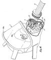
- the respirator shown in Figures 1 and 2 comprises a facepiece 1 which, as shown, comprises a full face mask covering the eyes, nose and mouth of the wearer, which is held on the wearer's head by retaining means extending around the back of the wearer's head, and which is peripherally sealed to the head of the wearer.
- the facepiece 1 is provided with an outlet provided with a one-way outlet or exhale valve 2 through which air leaves the mask and an inlet 3.
- the inlet 3 is connected by a flexible hose 4 to a pump unit 5.
- the pump unit 5 is, as shown, supported by a harness on the back of the wearer but may alternatively be supported by a similar harness on the front of the wearer.
- the unit 5 comprises a housing in which a pump comprising a fan, for example a centrifugal fan, and a battery operated d.c. motor driving the fan are housed and will be described in more detail hereafter.
- the pump unit housing has an outlet 8 defining the outlet of the fan and to which the hose 4 is connected, and one, or a plurality of, for example as shown two, inlets 10 connected to the fan inlet.
- Each of the housing inlets 10 is threaded to receive a filter canister 11, which may comprise a particulate filter material and/or a gas and/or vapour filter material.
- a filter canister 11 may be mounted on the or each or some of the inlets 10 and any unused inlets may be closed by a plug (not shown).
- the motor is connected, as shown, by a cable 27 of a motor energisation circuit to a separate unit comprising a casing housing one or more batteries 6 and optionally an on/off switch 7 operable by the wearer for controlling power supplied to the motor.
- a separate unit comprising a casing housing one or more batteries 6 and optionally an on/off switch 7 operable by the wearer for controlling power supplied to the motor.
- the battery or batteries and, where provided, the switch 7 may be mounted in and on the pump unit 5.
- the exhale valve 2 is biased to its closed position, for example by a helical compression spring 14, so that the valve will only open to permit air to flow out of the facepiece when the air within the facepiece is at a preset pressure P above atmospheric pressure.
- the valve cracking pressure may for example be within the range 150 to 600 Pascals.
- a one-way inlet valve 13 is mounted in the inlet 3 of the facepiece and permits air to flow from the pump to the facepiece.
- the valve 13 is arranged so thatthe valve will close as soon as the pressure downstream thereof within the facepiece exceeds that upstream thereof within the hose 4.
- the operating parameters of the pump unit 5 are selected relative to the operating parameters of the exhale valve 2 so that the pump unit will cease or substantially cease operating effectively when the pressure at the outlet is of the order of but slightly less than the predetermined pressure P at which the exhale valve 2 opens.
- the pump unit will operate normally and the inlet valve will be maintained open, the exhale valve being closed.
- the pressure within the facepiece will build up to a point at which it exceeds that in the hose 4.
- the valve 13 will close.
- the exhale valve will open shortly thereafter but meanwhile closure of valve 13 causes an increase in pressure within the hose to the point at which the pump unit will be placed in a condition in which it ceases or substantially ceases to operate effectively to draw air into the apparatus through the filters.
- the pressure between the filter canister or canisters and the pump means is sub-atmospheric.
- the pressure between the pump means and the filter canisters increases from the sub-atmospheric pressure towards atmospheric pressure to equalise the pressure differential across the filter canisters.
- the pressure in the region between the fan inlet and the filter canisters is sensed by a pressure sensor 12, which as shown is mounted in this region, and which causes control means to be operated to disconnect the motor of the pump means from the battery when the pressure rises to a preset level, for example between about 100 and 140 Pascals below atmospheric pressure.
- valve 2 Towards the end of exhalation, the pressure within the facepiece will fall causing valve 2 to close and valve 13 to open.
- the pressure sensor 12 is arranged to reverse the state of the control means on sensing this reduction of pressure to thus reenergise the motor.
- the pump unit will thus start operation again to supply the facepiece with the air required by the wearer for inhalation.
- the energisation of the pump unit can be made to vary during the breathing cycle of the wearer, not only to reduce the amount of air which is drawn into the respirator through the filters and which is not then breathed, but also to reduce the power required from the battery and thus to extend the life of the battery.
- the inertia of the pump unit 5 may be arranged so that the fan will continue to rotate after the motor has been de-energised to maintain the standing pressure in the hose 4, and so that the rotation will continue until the end of exhalation and the start of inhalation when the motor is re-energised. This additionally reduces the energy required each time the motor is re-energised to overcome the inertia of the pump unit.
- the facepiece 1 of this embodiment comprises an outer mask 15a which covers the face of the wearer and is peripherally sealed to the wearer's face, and an inner mask 15b which more closely surrounds the nose and mouth of the wearer.
- the outer mask is provided with the inlet 3 and the space within the inner mask communicates with the exhale valve 2 in the outlet, which conveniently penetrates both masks. Communication between the masks is provided by one or more apertures in the inner mask, the or each of which is provided with a one-way inlet valve 16.
- the valves 16 may for example be flap valves permitting flow of air from the outer mask to the inner mask but preventing flow of exhaled air into the total volume of the facepiece so as to limit the amount of exhaled air which may be re-breathed. If the inner mask is sufficiently well sealed to the wearer's face to prevent excessive leakage around the edges, the inlet valve 13 provided in inlet 3 may be omitted, the or each valve 16 performing its function.
- valve 13 comprises a flap valve comprising a flexible disc 20 which is seated over a seat 21 surrounding an opening in the passage of inlet 3 to the facepiece.
- the disc 20 is normally in its closed position seated on seat 21 and lifts from seat 21 to allow air to flow into the facepiece when the pressure within the facepiece falls below that in the hose 4.
- the or each valve 16 may be similarly constructed.
- the exhale valve 2 comprises a flap vale comprising a rigid disc 22 which seats against an outlet seat 23 surrounding the outlet opening and is biased to its closed position by a helical compression spring 14 which bears against the disc 22 and a part of the housing around the outlet. Air exits from the valve through openings 24 communicating with the opening in seat 23.
- the pump unit 5 shown in Figure 5 comprises a d.c. motor 26 connected by cable 27 to the battery and to the shaft 28 of a double centrifugal fan 20 whose outlet is connected to outlet 8 provided by the housing of the unit.
- Thefan inlet is connected, as shown, to two housing inlets 10, each of which is threaded to receive a filter canister 11.
- a preferred embodiment of the pressure sensor 12 is shown in Figure 3 and comprises a housing 30 the interior of which is separated into two chambers by a diaphragm 31, each chamber having an inlet 32, 33, one of which is placed in communication with atmospheric pressure and the other with pressure to be sensed.
- the diaphragm 30 carries one contact of a switch 12a, the other switch contact being fixed.
- inlet 33 is in communication with the region between the fan and the filter cartridge and the switch 12a is normally open being closed so long as the pressure in the region of the fan inlet is maintained below the preset level.
- the switch 12a is connected in series with the battery 6, on/off switch 7 and the fan motor 26 in the energisation circuit of the motor.
- the senor 12 may be arranged so that the switch 12a is open so long as the pressure in the region of the fan inlet is maintained below the preset level, and is closed when the pressure in the region of the fan inlet rises to the preset level to, for example, energise a relay which then causes disconnection of the motor from the battery.
- the energisation circuit may also include a by-pass circuit to by-pass the pressure sensor and the related control so that the respirator may be operated without the control provided by the sensor 12.
- the facepiece is connected to the pump unit and filter means by a flexible hose
- the hose may be omitted, the pump unit and filter means being mounted on or in the facepiece, as will be described hereafter.
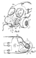
- the respirator shown in Figures 6 and 7 comprises an outer mask 15a with an inner mask 15b similar to the masks of the facepiece shown in Figure 2.
- the outer mask 15a fits peripherally against the wearer's face so as to be sealed thereto and holds the inner mask, which covers the nose and mouth of the wearer, against the wearer's face so that it is also sealed thereto.
- the inner mask may for example be made of rubber or a synthetic plastics material.
- the facepiece outlet and exhale valve 2 communicate with the inner mask and, for convenience, penetrate the outer mask, the two masks being sealed together at the periphery of the outlet.
- the inner mask is also provided with one or more, as shown two, apertures providing communication between the masks, the or each of which is provided with a one-way valve 16 permitting air to flow from the outer mask into the inner mask.
- the pump unit 5 is mounted within the outer mask 15a.
- the pump unit may take a variety of different forms.
- the housing of the pump unit has the form of a cross-tube 34 extending within the outer mask above the exhale valve laterally across the front of the outer mask.
- the tube 34 has an inlet 10 at one end, as shown the left hand end, which is also the facepiece inlet (3), opening laterally of the facepiece.
- the cross-tube 34 has an outlet opening intermediate its end which provides the pump unit outlet 8 and which communicates with the space within the outer mask.
- An axial fan 29 is mounted within the tube 34 adjacent that end provided with the inlet 10 to draw air into the tube 34 through inlet 10 and expel it through outlet 8.
- the fan 29 is driven by a d.c. motor 26 which is, as in the above described embodiment, battery operated and is connected by cable 27 to a separate unit housing the battery or batteries and optionally an on/off switch controlling power supplied to the motor.
- the inlet 10 of the facepiece and pump unit is threaded and receives a filter canister 11.
- a pressure sensor 12 is arranged in the region of the inlet of the fan to sense the pressure between the fan and the filter canister.
- the sensor 12 is conveniently mounted within the casing 34 adjacent the fan inlet and is associated with a switch 12a connected in the energisation circuit of the motor 26 as described in the preceding embodiment.
- valves 2 and 16 and the sensor 12 are preferably constructed as in the preceding embodiment and the operating parameters of the exhale valve in relation to those of the fan 29 are selected so that the respirator operates as described in relation to the embodiment of Figures 1 to 5. It will however be appreciated that, in this embodiment, control of the pump unit is more responsive to the breathing cycle of the wearer because of the omission of the volume of the flexible hose 4 between the facepiece and the pump unit.
- the inner mask 15b may be omitted or the valves 16 may be omitted.
- a one-way valve, replacing valve(s) 16 is then arranged in the path of air from the pump unit, e.g. in the region of outlet 8.
- the pump unit 5 is in the form of a module for connection to the inlet of the facepiece.
- the facepiece 1 has a construction similar to the facepiece of the embodiment of Figures 6 and 7 with an outer mask 15a and an inner mask 156 and the cross-tube 34 provided within the outer mask.
- the inner mask 15b communicates with the exhale valve 2 and with the outer mask through apertures provided with one-way valves 16.
- a one-way valve 13 may also be provided in the inlet 3 of the face mask (corresponding to inlet 10 in the embodiment of Figures 6 and 7).
- the pump unit 5 comprises an axial fan 29 driven by a d.c.
- the motor 26 and the unit housing has a threaded inlet 10 for receiving the outlet of a filter canister 11.
- the energisation circuit of the motor 26 is as described in relation to the embodiment of Figures 1 to 5 and includes the switch 12a associated with pressure sensor 12 which is mounted within the pump unit casing in the region of the fan inlet.
- the operation and operating parameters of this embodiment of respirator are exactly the same as those of the preceding embodiments and it has the additional advantage of the embodiment of Figure 6 and 7.
- FIG 10 shows an alternative form of pump unit 5 for connection to the facepiece of Figure 8 in place of the pump unit shown in Figures 8 and 9.
- the fan 29 is a centrifugal fan which is, as in the preceding embodiments, driven directly by a d.c. motor whose energisation circuit is exactly the same as that of the embodiment of Figures 1 to 5.
- the pressure sensor 12 is, for convenience, mounted within a part of the housing of the pump unit 5 in which the motor 26 is located and which is separate from that in which fan 29 is located. This part of the housing is vented to the atmosphere to provide atmospheric pressure in the appropriate one of the chambers of the pressure sensor 12.
- the other chamber is connected by a duct 44 to the region of the inlet of the fan 29 so that this other chamber of the pressure sensor is at the pressure prevailing in the region of the fan inlet.
- the inlet 10 of the pump unit is, as in the embodiment of Figures 8 and 9, threaded to receive a filter canister 11.
- the operation and operating parameters of this embodiment of respirator are exactly the same as described in - relation to the embodiment of Figures 1 to 5.
Claims (13)
Priority Applications (1)
| Application Number | Priority Date | Filing Date | Title |
|---|---|---|---|
| AT84303822T ATE34081T1 (de) | 1983-06-07 | 1984-06-06 | Atmungsgeraet. |
Applications Claiming Priority (4)
| Application Number | Priority Date | Filing Date | Title |
|---|---|---|---|
| GB8315589 | 1983-06-07 | ||
| GB838315589A GB8315589D0 (en) | 1983-06-07 | 1983-06-07 | Breathing apparatus |
| GB838330142A GB8330142D0 (en) | 1983-11-11 | 1983-11-11 | Breathing apparatus |
| GB8330142 | 1983-11-11 |
Publications (3)
| Publication Number | Publication Date |
|---|---|
| EP0130707A2 EP0130707A2 (fr) | 1985-01-09 |
| EP0130707A3 EP0130707A3 (en) | 1985-08-21 |
| EP0130707B1 true EP0130707B1 (fr) | 1988-05-11 |
Family
ID=26286305
Family Applications (1)
| Application Number | Title | Priority Date | Filing Date |
|---|---|---|---|
| EP84303822A Expired EP0130707B1 (fr) | 1983-06-07 | 1984-06-06 | Appareil respiratoire |
Country Status (11)
| Country | Link |
|---|---|
| US (1) | US4590951A (fr) |
| EP (1) | EP0130707B1 (fr) |
| AU (1) | AU559307B2 (fr) |
| CA (1) | CA1218579A (fr) |
| DE (1) | DE3471008D1 (fr) |
| ES (1) | ES8504469A1 (fr) |
| FI (1) | FI73134C (fr) |
| GB (1) | GB2141348B (fr) |
| HK (1) | HK8687A (fr) |
| MY (1) | MY8700189A (fr) |
| NO (1) | NO842275L (fr) |
Cited By (1)
| Publication number | Priority date | Publication date | Assignee | Title |
|---|---|---|---|---|
| GB2386075B (en) * | 2000-08-07 | 2005-02-02 | Secr Defence | Respirators |
Families Citing this family (150)
| Publication number | Priority date | Publication date | Assignee | Title |
|---|---|---|---|---|
| DE3546673C2 (en) * | 1984-11-15 | 1991-08-29 | Gesellschaft Fuer Geraetebau Mbh, 4600 Dortmund, De | Plastic foil respirator |
| US4744356A (en) * | 1986-03-03 | 1988-05-17 | Greenwood Eugene C | Demand oxygen supply device |
| DE3701695A1 (de) * | 1987-01-22 | 1988-08-04 | Draegerwerk Ag | Schutzhaube fuer den notfall |
| GB2203050B (en) * | 1987-04-06 | 1991-07-31 | Cam Lock | Respirator |
| US4807616A (en) * | 1987-07-09 | 1989-02-28 | Carmeli Adahan | Portable ventilator apparatus |
| US5046492A (en) * | 1988-07-15 | 1991-09-10 | Stackhouse Wyman H | Clean room helmet system |
| IL87156A (en) * | 1988-07-20 | 1993-05-13 | Eagle | Forced-ventilation filtration unit particularly for respiration device |
| EP0352938B1 (fr) | 1988-07-26 | 1993-10-06 | RACAL HEALTH & SAFETY LIMITED | Appareil respiratoire |
| DE3843486A1 (de) * | 1988-12-23 | 1990-06-28 | Draegerwerk Ag | Atemschutzgeraet mit geblaeseunterstuetzung und regeneration der atemfilter |
| CH679122A5 (fr) * | 1989-09-29 | 1991-12-31 | Micronel Ag | |
| US4955373A (en) * | 1989-10-16 | 1990-09-11 | Maguire Iii John N | Air breathing assembly and air filter attachment therein |
| US5003974A (en) * | 1989-10-27 | 1991-04-02 | Mou Lin Her | First-aid gas mask |
| US5042474A (en) * | 1990-04-16 | 1991-08-27 | Williamson Ian M | Self-contained clean room respiration system with breathed air exhausting |
| US5245994A (en) * | 1991-01-08 | 1993-09-21 | National Science Council | Air cleaning and supplying system equipped to a helmet for a motorcyclist |
| SE467041B (sv) * | 1991-04-12 | 1992-05-18 | Sundstrom Safety Ab | Saett att styra en luftfoersoerjningsenhet andningssynkroniserat foer ett andningsskydd, som aatminstone taecker baerarens naesa och/eller mun |
| US5372130A (en) * | 1992-02-26 | 1994-12-13 | Djs&T Limited Partnership | Face mask assembly and method having a fan and replaceable filter |
| US5193347A (en) * | 1992-06-19 | 1993-03-16 | Apisdorf Yair J | Helmet-mounted air system for personal comfort |
| DE4307754A1 (de) * | 1992-07-23 | 1994-04-07 | Johannes Dipl Ing Geisen | System und Verfahren zum kontrollierten Zuführen oder Abführen von Atemluft |
| DE9209893U1 (de) * | 1992-07-23 | 1994-01-20 | Geisen Bernhard | System zur Dekontamination von Atem- oder Außenluft |
| GB9307733D0 (en) * | 1993-04-14 | 1993-06-02 | Msa Britain Ltd | Respiratory protective device |
| US5394870A (en) * | 1993-09-03 | 1995-03-07 | Minnesota Mining And Manufacturing Company | Respirator blower unit housing with pommel-like strap support member comprising lower exterior support surface |
| US5427090A (en) * | 1993-10-25 | 1995-06-27 | Hipskind; Donald W. | Portable breathing apparatus for an enclosed space |
| US5515843A (en) * | 1994-01-24 | 1996-05-14 | Chang; Huang | Three-layer helmet assembly with breathing gas throttle |
| US5906203A (en) * | 1994-08-01 | 1999-05-25 | Safety Equipment Sweden Ab | Breathing apparatus |
| US5592935A (en) * | 1995-05-03 | 1997-01-14 | Minnesota Mining And Manufacturing Company | Positive/negative air pressure adaptor for use with respirators |
| USD383592S (en) * | 1996-02-21 | 1997-09-16 | Surgical Specialty Products, Inc. | Surgical gown and hood |
| US5655374A (en) * | 1996-02-21 | 1997-08-12 | Surgical Specialty Products, Inc. | Surgical suit |
| US5730118A (en) * | 1996-02-27 | 1998-03-24 | Hermanson; Susan Thomas | Carrier for asthma inhaler |
| AU9182298A (en) | 1997-09-18 | 1999-04-05 | Caradyne (R & D) Limited | Portable respirator |
| US6279573B1 (en) * | 1998-03-10 | 2001-08-28 | 3M Innovative Properties Company | Breathing tube connection for respiratory protective headgear |
| AUPP240198A0 (en) * | 1998-03-17 | 1998-04-09 | Resmed Limited | An apparatus for supplying breathable gas |
| US6602227B1 (en) * | 1998-09-25 | 2003-08-05 | Sherwood Services Ag | Surgical system console |
| US6382208B2 (en) | 1998-11-02 | 2002-05-07 | Board Of Regents University Of Nebraska | System for controlling the internal temperature of a respirator |
| US6371116B1 (en) | 1999-06-24 | 2002-04-16 | Todd A. Resnick | Method and apparatus for pressurizing a protective hood enclosure with exhaled air |
| US6481019B2 (en) | 2000-01-18 | 2002-11-19 | Stryker Instruments | Air filtration system including a helmet assembly |
| AUPQ664400A0 (en) * | 2000-04-03 | 2000-05-04 | Safety Equipment Australia Pty Ltd | Ventilation system for protective suit |
| US7007690B1 (en) * | 2000-08-31 | 2006-03-07 | The United States Of America As Represented By The Secretary Of The Army | Advanced chemical/biological crew mask |
| WO2002026287A2 (fr) * | 2000-09-28 | 2002-04-04 | Invacare Corporation | Régulation à deux niveaux de la ventilation spontanée en pression positive continue sur la base du dioxyde de carbone |
| ITMI20010097A1 (it) * | 2001-01-19 | 2002-07-19 | Luca Florindo De | Depuratore d'aria portatile individuale |
| CA2445797C (fr) | 2001-04-23 | 2009-01-06 | Scott Technologies, Inc. | Casque respirateur |
| EP1252914A1 (fr) * | 2001-04-24 | 2002-10-30 | Kasco S.r.l. | Unité de pompage d'air purifié pour dispositifs de protection à ventilation assistée |
| JP3726886B2 (ja) | 2001-06-29 | 2005-12-14 | 興研株式会社 | 呼吸装置 |
| JP4264619B2 (ja) * | 2001-10-12 | 2009-05-20 | 山本光学株式会社 | 呼吸用保護具 |
| US6834646B2 (en) | 2001-12-19 | 2004-12-28 | Testa Technologies T.T. Ltd. | Respiratory hood |
| US20070240716A1 (en) * | 2002-02-15 | 2007-10-18 | Marx Alvin J | Personal air filtering and isolation device |
| DE10210878B4 (de) * | 2002-03-12 | 2018-01-04 | Drägerwerk AG & Co. KGaA | Vorrichtung zur Atemunterstützung |
| US20040182394A1 (en) * | 2003-03-21 | 2004-09-23 | Alvey Jeffrey Arthur | Powered air purifying respirator system and self contained breathing apparatus |
| US20060048777A1 (en) * | 2003-03-21 | 2006-03-09 | Interspiro, Inc. | Apparatus and method for providing breathable air and bodily protection in a contaminated environment |
| SE526342C2 (sv) * | 2003-06-03 | 2005-08-23 | Saab Ab | Anordning och metod vid gasmask |
| DE10337138A1 (de) * | 2003-08-11 | 2005-03-17 | Freitag, Lutz, Dr. | Verfahren und Anordnung zur Atmungsunterstützung eines Patienten sowie Luftröhrenprothese und Katheter |
| US7588033B2 (en) | 2003-06-18 | 2009-09-15 | Breathe Technologies, Inc. | Methods, systems and devices for improving ventilation in a lung area |
| US7152598B2 (en) * | 2003-06-23 | 2006-12-26 | Invacare Corporation | System and method for providing a breathing gas |
| FR2856930B1 (fr) * | 2003-07-04 | 2007-09-07 | Saime Sarl | Dispositif d'aide a la respiration a turbine et capteur modulaires. |
| US6990691B2 (en) * | 2003-07-18 | 2006-01-31 | Depuy Products, Inc. | Head gear apparatus |
| DE10332899B3 (de) * | 2003-07-19 | 2004-09-30 | Dräger Safety AG & Co. KGaA | Atemschutzvorrichtung mit einem Verdichter |
| US7406966B2 (en) | 2003-08-18 | 2008-08-05 | Menlo Lifesciences, Llc | Method and device for non-invasive ventilation with nasal interface |
| US7647927B2 (en) * | 2003-08-22 | 2010-01-19 | Wilcox Industries Corp. | Self-contained breathing system |
| HK1062767A2 (en) * | 2003-08-26 | 2004-10-29 | Winsource Ind Ltd | Isolation suit with two-way air supply/disinfection pump |
| WO2005028009A1 (fr) | 2003-09-25 | 2005-03-31 | Resmed Limited | Masque de ventilateur et systeme |
| US8925545B2 (en) | 2004-02-04 | 2015-01-06 | Breathe Technologies, Inc. | Methods and devices for treating sleep apnea |
| GB0406291D0 (en) | 2004-03-19 | 2004-04-21 | Scott Health & Safety Ltd | Respirators |
| US8479727B2 (en) * | 2004-05-04 | 2013-07-09 | The United States Of America As Represented By The Secretary Of The Army | Enhanced chemical/biological respiratory protection system |
| US20060096596A1 (en) * | 2004-11-05 | 2006-05-11 | Occhialini James M | Wearable system for positive airway pressure therapy |
| US20060096593A1 (en) * | 2004-11-11 | 2006-05-11 | Grilliot William L | Protective garment equipped to maintain positive gas pressure in space between protective garment and inner clothes worn by wearer |
| DE602006014807D1 (de) | 2005-03-24 | 2010-07-22 | Stryker Corp | Personenschutzsystem |
| US20090014002A1 (en) * | 2005-04-14 | 2009-01-15 | Honeywell International Inc. | Air filter assembly |
| US7937775B2 (en) | 2005-08-09 | 2011-05-10 | Microtek Medical, Inc. | Surgical protective head gear assembly including high volume air delivery system |
| US20070050898A1 (en) * | 2005-08-09 | 2007-03-08 | Larson Keith A | Surgical protective system and assembly having a head gear assembly supporting a surgical garment and air delivery system |
| US7533670B1 (en) | 2005-09-20 | 2009-05-19 | Breathe Technologies, Inc. | Systems, methods and apparatus for respiratory support of a patient |
| EP2012858A2 (fr) | 2006-04-10 | 2009-01-14 | Aeiomed, INC. | Appareil et méthodes pour administrer des thérapies en pression positive aux voies aeriennes |
| US7516743B2 (en) * | 2006-04-20 | 2009-04-14 | Viasys Sleep Systems, Llc | Continuous positive airway pressure device and configuration for employing same |
| WO2007124108A2 (fr) * | 2006-04-21 | 2007-11-01 | Cardinal Health 205, Inc. | Appareil de thérapie respiratoire autonome pour conformité avec le patient et efficacité thérapeutique améliorées |
| US20070272244A1 (en) * | 2006-04-25 | 2007-11-29 | Witmer Warner H | Fluidic barrier |
| CA2652544A1 (fr) | 2006-05-18 | 2007-12-13 | Breathe Technologies, Inc. | Entretoise de tracheotomie, methode de tracheotomie et dispositif d'insertion de ladite entretoise |
| US20070283961A1 (en) * | 2006-06-07 | 2007-12-13 | Hsieh Hsin-Mao | Air purifier for a protective garment |
| WO2008019102A2 (fr) | 2006-08-03 | 2008-02-14 | Breathe Technologies, Inc. | Procédés et dispositifs de support respiratoire peu invasif |
| EP2063945B1 (fr) | 2006-09-07 | 2019-07-03 | ResMed Ltd. | Masque et système générateur de flux |
| US20080060647A1 (en) * | 2006-09-12 | 2008-03-13 | Invacare Corporation | System and method for delivering a breathing gas |
| JP4612606B2 (ja) * | 2006-10-04 | 2011-01-12 | 興研株式会社 | ブロワー付マスク装置 |
| EP3560538B1 (fr) * | 2007-03-02 | 2023-04-26 | ResMed Pty Ltd | Masque respiratoire |
| JP5373640B2 (ja) * | 2007-03-21 | 2013-12-18 | レスメド パリ | 人工呼吸器に使用される気体制御バルブ |
| WO2008144589A1 (fr) | 2007-05-18 | 2008-11-27 | Breathe Technologies, Inc. | Procédés et dispositifs pour détecter la respiration et fournir une thérapie de ventilation |
| CA2696773A1 (fr) | 2007-08-23 | 2009-02-26 | Invacare Corporation | Procede et dispositif de reglage de la pression recherchee dans des dispositifs de pression positive pour voies respiratoires |
| CA2700878C (fr) | 2007-09-26 | 2018-07-24 | Breathe Technologies, Inc. | Procedes et dispositifs permettant d'assister le flux d'inspiration et d'expiration dans une therapie par ventilation |
| US20100313869A1 (en) * | 2007-10-12 | 2010-12-16 | Claudiu Iulian Muntele | Catalytic reactor hetero-structure and applications |
| US8234722B2 (en) * | 2007-12-14 | 2012-08-07 | Stryker Corporation | Personal protection system with head unit having easy access controls and protective covering having glare avoiding face shield |
| US20090314295A1 (en) * | 2007-12-19 | 2009-12-24 | E.D. Bullard Company | Powered air purifying respirator |
| NZ574584A (en) * | 2008-01-31 | 2010-10-29 | Resmed Ltd | Respiratory Apparatus including a flow generator with two impellers and a directional stator |
| CA2720226C (fr) * | 2008-04-04 | 2017-09-19 | Pierre Legare | Dispositifs de filtration d'air |
| EP2274036A4 (fr) | 2008-04-18 | 2014-08-13 | Breathe Technologies Inc | Procédés et dispositifs pour détecter la respiration et commander des fonctions d'insufflateur |
| JP5758799B2 (ja) | 2008-04-18 | 2015-08-05 | ブリーズ・テクノロジーズ・インコーポレーテッド | 呼吸作用を感知し、人工呼吸器の機能を制御するための方法およびデバイス |
| EP2326376B1 (fr) * | 2008-08-22 | 2019-07-24 | Breathe Technologies, Inc. | Dispositifs pour fournir une ventilation mécanique avec une interface de voies respiratoires ouvertes |
| JP5711661B2 (ja) | 2008-10-01 | 2015-05-07 | ブリーズ・テクノロジーズ・インコーポレーテッド | バイオフィードバックモニタリング及び患者の活動及び健康を改善する制御装置を有するベンチレータ |
| US8166972B2 (en) * | 2008-11-14 | 2012-05-01 | Shahriar Daliri | Antiseptic mask and method of using antiseptic mask |
| AU2009334356A1 (en) * | 2008-12-30 | 2011-08-18 | Koninklijke Philips Electronics, N.V. | Mask and method for delivering a therapeutic breathable substance |
| WO2010080709A1 (fr) | 2009-01-08 | 2010-07-15 | Hancock Medical | Systèmes de pression des voies respiratoires positifs intermittents et autonomes, et méthodes de traitement de l'apnée du sommeil, du ronflement et d'autres troubles respiratoires |
| US9132250B2 (en) | 2009-09-03 | 2015-09-15 | Breathe Technologies, Inc. | Methods, systems and devices for non-invasive ventilation including a non-sealing ventilation interface with an entrainment port and/or pressure feature |
| US20120017895A1 (en) * | 2009-02-03 | 2012-01-26 | Avon Protection Systems, Inc. | Respirator kit and contoured plenum therefor |
| US9962512B2 (en) | 2009-04-02 | 2018-05-08 | Breathe Technologies, Inc. | Methods, systems and devices for non-invasive ventilation including a non-sealing ventilation interface with a free space nozzle feature |
| JP5575223B2 (ja) | 2009-04-02 | 2014-08-20 | ブリーズ・テクノロジーズ・インコーポレーテッド | 非侵襲性換気システム、患者の気道閉塞を少なくするシステムおよび睡眠時無呼吸を治療するデバイス |
| US20150114397A1 (en) * | 2009-04-09 | 2015-04-30 | Jeffery C. Litz | Chemical and biological protection mask |
| US10238822B2 (en) | 2009-05-29 | 2019-03-26 | Resmed Limited | PAP system |
| DE102009025060B4 (de) | 2009-06-10 | 2014-09-25 | Alexander Luchinskiy | Verfahren und Einrichtung zum Schutz der Atemwege |
| GB2472592A (en) * | 2009-08-11 | 2011-02-16 | 3M Innovative Properties Co | A control unit for respirator |
| NZ628624A (en) | 2009-08-28 | 2015-10-30 | Resmed Ltd | Pap system |
| CA2774902C (fr) | 2009-09-03 | 2017-01-03 | Breathe Technologies, Inc. | Procedes, systemes et dispositifs de ventilation non invasive comprenant une interface de ventilation non etanche avec orifice d'entrainement et/ou element de pression |
| WO2011043262A1 (fr) * | 2009-10-07 | 2011-04-14 | 株式会社重松製作所 | Dispositif respiratoire |
| WO2011050059A1 (fr) * | 2009-10-20 | 2011-04-28 | Michael Gerard Lalonde | Appareil intégré à pression positive pour voies aériennes |
| CN104314843B (zh) | 2009-11-19 | 2018-07-24 | 瑞思迈发动机及马达技术股份有限公司 | 鼓风机 |
| US9616192B2 (en) | 2010-03-25 | 2017-04-11 | Resmed Paris Sas | Breathable gas inlet control device for respiratory treatment apparatus |
| WO2012024342A1 (fr) | 2010-08-16 | 2012-02-23 | Breathe Technologies, Inc. | Procédés, systèmes et dispositifs utilisant de l'oxygène liquide pour fournir une assistance ventilatoire |
| BR112013006931A2 (pt) | 2010-09-30 | 2016-07-12 | Breathe Technologies Inc | métodos, sistemas e dispositivos para umidificação de trato respiratório |
| FR2966839B1 (fr) * | 2010-10-27 | 2012-11-30 | Bertin Technologies Sa | Dispositif portable de collecte de particules et de microorganismes |
| US8327846B2 (en) | 2011-02-08 | 2012-12-11 | Hancock Medical, Inc. | Positive airway pressure system with head position control |
| US8973173B2 (en) | 2011-04-04 | 2015-03-10 | Todd E. ELAM | Environmental system for motorsports helmets |
| US10137264B2 (en) | 2011-07-13 | 2018-11-27 | Fisher & Paykel Healthcare Limited | Respiratory assistance apparatus |
| EP2731656B1 (fr) | 2011-07-13 | 2017-03-22 | Fisher & Paykel Healthcare Limited | Ensemble rotor et moteur |
| GB2508184A (en) * | 2012-11-22 | 2014-05-28 | 3M Innovative Properties Co | Powered exhaust apparatus for respiratory device |
| AU2013101734A4 (en) | 2012-12-18 | 2015-09-24 | Fisher & Paykel Healthcare Limited | Impeller and motor assembly |
| WO2014117179A1 (fr) | 2013-01-28 | 2014-07-31 | Hancock Medical, Inc. | Dispositifs et procédés de commande de position destinés à être utilisés avec des systèmes de pression de voie aérienne positive |
| US11141552B2 (en) | 2013-03-15 | 2021-10-12 | Breas Medical, Inc. | Systems and methods for providing low-noise positive airway pressure |
| WO2014145912A1 (fr) * | 2013-03-15 | 2014-09-18 | Human Design Medical, Llc | Systèmes et méthodes de fourniture de pression positive continue dans une structure de type tubulaire |
| US20170189727A1 (en) * | 2014-06-04 | 2017-07-06 | Free Air, Inc. | Systems and methods for removing ultra-fine particles from air |
| CN104014087B (zh) * | 2014-06-23 | 2017-02-15 | 王�华 | 一种智能型过滤鼻罩 |
| DE102015009772A1 (de) | 2014-08-01 | 2016-02-04 | Alexander Luchinskiy | Verfahren und Einrichtung zur Schutz der Atemwege |
| WO2016028525A1 (fr) | 2014-08-18 | 2016-02-25 | Hancock Medical, Inc. | Dispositif pap portable avec humidification |
| EP4173677A1 (fr) | 2014-12-04 | 2023-05-03 | ResMed Pty Ltd | Un ventilateur à plusieurs étages |
| USD776802S1 (en) | 2015-03-06 | 2017-01-17 | Hancock Medical, Inc. | Positive airway pressure system console |
| WO2017065853A1 (fr) * | 2015-10-16 | 2017-04-20 | Yang Song | Masque facial à filtre de particules ayant une assistance respiratoire à ventilateur |
| AU2017205201B2 (en) * | 2016-01-07 | 2022-03-03 | Thi Total Healthcare Innovation Gmbh | Donnable barrier devices, systems, and methods with touchless control |
| US10159857B2 (en) | 2016-03-02 | 2018-12-25 | Paul Key | Personal air filtration apparatus and method |
| JP2019518520A (ja) | 2016-05-19 | 2019-07-04 | ハンコック メディカル, インコーポレイテッド | 位置閉塞性睡眠時無呼吸検出システム |
| EP3615820A4 (fr) | 2017-04-23 | 2021-01-06 | Fisher & Paykel Healthcare Limited | Appareil d'assistance respiratoire |
| US10792449B2 (en) | 2017-10-03 | 2020-10-06 | Breathe Technologies, Inc. | Patient interface with integrated jet pump |
| WO2019093906A1 (fr) * | 2017-11-13 | 2019-05-16 | Safeback As | Dispositif de survie en avalanche comprenant un appareil respiratoire |
| NO20171795A1 (en) * | 2017-11-13 | 2019-05-14 | Safeback As | Avalanche survival device |
| US11433262B1 (en) * | 2018-11-01 | 2022-09-06 | The United States Of America As Represented By The Secretary Of The Army | Positive pressure dog respirator |
| US10782708B2 (en) * | 2018-11-07 | 2020-09-22 | International Business Machines Corporation | Automatic shutoff continuous positive air pressure system |
| WO2021195354A1 (fr) * | 2020-03-26 | 2021-09-30 | Alexander Werjefelt | Dispositif de protection contre les pathogènes |
| IT202000006529A1 (it) * | 2020-03-27 | 2021-09-27 | Santi Tedesco | Dispositivo di protezione ed isolamento individuale contro sostanze inquinanti e microorganismi e gruppo filtrante per dispositivi di protezione ed isolamento |
| EP4142909A1 (fr) * | 2020-04-27 | 2023-03-08 | W.L. Gore & Associates, Inc. | Cartouche filtrante et ses procédés de fabrication et d'utilisation |
| US10870076B1 (en) | 2020-06-05 | 2020-12-22 | Celios Corporation | Air filtration system, air filtration device, and air filtration module for use therewith |
| US10926209B1 (en) | 2020-06-05 | 2021-02-23 | Celios Corporation | Air filtration system, air filtration device, and air filtration module for use therewith |
| TR202009416A2 (tr) * | 2020-06-17 | 2020-07-21 | Maltepe Ueniversitesi Teknoloji Transfer Ofisi Anonim Sirketi | Dezenfekte hava akişli koruma si̇perli̇kli̇ başlik |
| GB2597745A (en) * | 2020-07-31 | 2022-02-09 | World Wide Welding Ltd | Powered air purifying respirator assembly |
| US20210196992A1 (en) * | 2020-11-09 | 2021-07-01 | Shang-Fang Yu | Combination air filter and protective mask |
| US11896857B2 (en) * | 2021-01-14 | 2024-02-13 | Ford Global Technologies, Llc | Personal air purifying respirator |
| WO2023085947A1 (fr) * | 2021-11-12 | 2023-05-19 | Safeback As | Dispositif de survie pour l'alimentation constante en air respirable dans un environnement |
| JP7296670B1 (ja) | 2021-12-07 | 2023-06-23 | 株式会社クリスタルシステム | ウイルス感染防止装置 |
| US20230321466A1 (en) * | 2022-03-26 | 2023-10-12 | D. Wheatley Enterprises, Inc. | Compact powered air purifying respirator having improved airflow efficiency |
Family Cites Families (12)
| Publication number | Priority date | Publication date | Assignee | Title |
|---|---|---|---|---|
| FR785223A (fr) * | 1934-09-21 | 1935-08-05 | Cela Holding S A | Appareil portatif de protection contre les gaz |
| CH202373A (fr) * | 1936-06-11 | 1939-01-15 | Bez Casimir | Appareil respiratoire. |
| GB560877A (en) * | 1942-10-23 | 1944-04-25 | Man Nathanson | Improvements in and relating to gas masks |
| GB1317172A (en) * | 1970-05-21 | 1973-05-16 | Ml Aviation Co Ltd | Respirators |
| DE2108757C3 (de) * | 1971-02-24 | 1974-01-17 | Egon Georg 8000 Muenchen Weishaar | Vorrichtung zur Blutabsaugung aus einer Operationswunde und Zuführung zu einer Herz-Lungen-Maschine |
| GB1426432A (en) * | 1972-05-09 | 1976-02-25 | Nat Res Dev | Respirators |
| GB1495020A (en) * | 1974-01-16 | 1977-12-14 | Nat Res Dev | Respirators |
| GB2032284B (en) * | 1978-10-02 | 1982-11-10 | Racal Safety Ltd | Breathing apparatus |
| GB2058577A (en) * | 1979-09-25 | 1981-04-15 | Racal Safety Ltd | Improvements in and relating to breathing apparatus |
| US4430995A (en) * | 1981-05-29 | 1984-02-14 | Hilton Joseph R | Power assisted air-purifying respirators |
| AU554194B2 (en) * | 1982-05-13 | 1986-08-14 | Minnesota Mining And Manufacturing Company | Respirator |
| US4502480A (en) * | 1983-02-24 | 1985-03-05 | Yamamoto Kogaku Co., Ltd. | Helmet equipped with device for supplying atmospheric air |
-
1984
- 1984-06-06 ES ES533165A patent/ES8504469A1/es not_active Expired
- 1984-06-06 EP EP84303822A patent/EP0130707B1/fr not_active Expired
- 1984-06-06 CA CA000456016A patent/CA1218579A/fr not_active Expired
- 1984-06-06 US US06/617,910 patent/US4590951A/en not_active Expired - Fee Related
- 1984-06-06 GB GB08414429A patent/GB2141348B/en not_active Expired
- 1984-06-06 FI FI842275A patent/FI73134C/fi not_active IP Right Cessation
- 1984-06-06 NO NO842275A patent/NO842275L/no unknown
- 1984-06-06 DE DE8484303822T patent/DE3471008D1/de not_active Expired
- 1984-06-06 AU AU29143/84A patent/AU559307B2/en not_active Expired
-
1987
- 1987-01-22 HK HK86/87A patent/HK8687A/xx not_active IP Right Cessation
- 1987-12-30 MY MY189/87A patent/MY8700189A/xx unknown
Cited By (1)
| Publication number | Priority date | Publication date | Assignee | Title |
|---|---|---|---|---|
| GB2386075B (en) * | 2000-08-07 | 2005-02-02 | Secr Defence | Respirators |
Also Published As
| Publication number | Publication date |
|---|---|
| ES533165A0 (es) | 1985-04-16 |
| AU2914384A (en) | 1984-12-13 |
| EP0130707A3 (en) | 1985-08-21 |
| DE3471008D1 (en) | 1988-06-16 |
| FI73134B (fi) | 1987-05-29 |
| GB8414429D0 (en) | 1984-07-11 |
| US4590951A (en) | 1986-05-27 |
| FI73134C (fi) | 1987-09-10 |
| MY8700189A (en) | 1987-12-31 |
| CA1218579A (fr) | 1987-03-03 |
| AU559307B2 (en) | 1987-03-05 |
| HK8687A (en) | 1987-01-28 |
| EP0130707A2 (fr) | 1985-01-09 |
| FI842275A (fi) | 1984-12-08 |
| FI842275A0 (fi) | 1984-06-06 |
| NO842275L (no) | 1984-12-10 |
| GB2141348B (en) | 1986-06-18 |
| ES8504469A1 (es) | 1985-04-16 |
| GB2141348A (en) | 1984-12-19 |
Similar Documents
| Publication | Publication Date | Title |
|---|---|---|
| EP0130707B1 (fr) | Appareil respiratoire | |
| US4971052A (en) | Breathing apparatus | |
| EP0066451B1 (fr) | Appareil respiratoire comportant une purification de l'air assistée par un moteur | |
| EP0164946A2 (fr) | Appareils respiratoires | |
| GB2032284A (en) | Improvements in and relating to breathing apparatus | |
| EP0094757B1 (fr) | Appareil respiratoire | |
| EP1729856B1 (fr) | Respirateurs | |
| CN107735148B (zh) | 用于个人防护呼吸装置的动力排气设备 | |
| WO2018132587A1 (fr) | Appareil électrique pour dispositif de protection respiratoire individuel | |
| JP2008535570A (ja) | 空気供給/空気浄化組合せシステム | |
| US20060060193A1 (en) | Respirator | |
| EP0241188A1 (fr) | Appareils respiratoires | |
| GB2058577A (en) | Improvements in and relating to breathing apparatus | |
| JPS6068869A (ja) | 呼吸保護器 | |
| CA2196166A1 (fr) | Respirateur | |
| GB2173705A (en) | Dust filter respirator | |
| EP3797837A1 (fr) | Appareil d'échappement électrique pour dispositif de protection personnelle respiratoire | |
| EP0108560A1 (fr) | Unité d'alimentation d'air à moteur pour respirateurs | |
| JPS612878A (ja) | ポンプ装置を備えたガスマスク | |
| WO2023174461A1 (fr) | Appareil respiratoire et procédé de commande de l'appareil respiratoire | |
| WO1989002293A1 (fr) | Appareil respiratoire | |
| CA2139723A1 (fr) | Masque protecteur pressurise muni d'un ventilateur a pulmo-commande presentant une consommation d'energie electrique optimale |
Legal Events
| Date | Code | Title | Description |
|---|---|---|---|
| PUAI | Public reference made under article 153(3) epc to a published international application that has entered the european phase |
Free format text: ORIGINAL CODE: 0009012 |
|
| AK | Designated contracting states |
Designated state(s): AT BE CH DE FR IT LI LU NL SE |
|
| PUAL | Search report despatched |
Free format text: ORIGINAL CODE: 0009013 |
|
| AK | Designated contracting states |
Designated state(s): AT BE CH DE FR IT LI LU NL SE |
|
| 17P | Request for examination filed |
Effective date: 19851205 |
|
| 17Q | First examination report despatched |
Effective date: 19870202 |
|
| GRAA | (expected) grant |
Free format text: ORIGINAL CODE: 0009210 |
|
| AK | Designated contracting states |
Kind code of ref document: B1 Designated state(s): AT BE CH DE FR IT LI LU NL SE |
|
| PG25 | Lapsed in a contracting state [announced via postgrant information from national office to epo] |
Ref country code: NL Effective date: 19880511 Ref country code: LI Effective date: 19880511 Ref country code: IT Free format text: LAPSE BECAUSE OF FAILURE TO SUBMIT A TRANSLATION OF THE DESCRIPTION OR TO PAY THE FEE WITHIN THE PRESCRIBED TIME-LIMIT;WARNING: LAPSES OF ITALIAN PATENTS WITH EFFECTIVE DATE BEFORE 2007 MAY HAVE OCCURRED AT ANY TIME BEFORE 2007. THE CORRECT EFFECTIVE DATE MAY BE DIFFERENT FROM THE ONE RECORDED. Effective date: 19880511 Ref country code: CH Effective date: 19880511 Ref country code: BE Effective date: 19880511 Ref country code: AT Effective date: 19880511 |
|
| REF | Corresponds to: |
Ref document number: 34081 Country of ref document: AT Date of ref document: 19880515 Kind code of ref document: T |
|
| REF | Corresponds to: |
Ref document number: 3471008 Country of ref document: DE Date of ref document: 19880616 |
|
| ET | Fr: translation filed | ||
| PG25 | Lapsed in a contracting state [announced via postgrant information from national office to epo] |
Ref country code: LU Free format text: LAPSE BECAUSE OF NON-PAYMENT OF DUE FEES Effective date: 19880630 |
|
| REG | Reference to a national code |
Ref country code: CH Ref legal event code: PL |
|
| NLV1 | Nl: lapsed or annulled due to failure to fulfill the requirements of art. 29p and 29m of the patents act | ||
| PLBE | No opposition filed within time limit |
Free format text: ORIGINAL CODE: 0009261 |
|
| STAA | Information on the status of an ep patent application or granted ep patent |
Free format text: STATUS: NO OPPOSITION FILED WITHIN TIME LIMIT |
|
| 26N | No opposition filed | ||
| EAL | Se: european patent in force in sweden |
Ref document number: 84303822.5 |
|
| REG | Reference to a national code |
Ref country code: FR Ref legal event code: TP |
|
| PGFP | Annual fee paid to national office [announced via postgrant information from national office to epo] |
Ref country code: SE Payment date: 20030619 Year of fee payment: 20 Ref country code: FR Payment date: 20030619 Year of fee payment: 20 |
|
| PGFP | Annual fee paid to national office [announced via postgrant information from national office to epo] |
Ref country code: DE Payment date: 20030630 Year of fee payment: 20 |
|
| EUG | Se: european patent has lapsed |