EP0129485B1 - Kabelstruktur und ihre Anwendungen - Google Patents
Kabelstruktur und ihre Anwendungen Download PDFInfo
- Publication number
- EP0129485B1 EP0129485B1 EP84401269A EP84401269A EP0129485B1 EP 0129485 B1 EP0129485 B1 EP 0129485B1 EP 84401269 A EP84401269 A EP 84401269A EP 84401269 A EP84401269 A EP 84401269A EP 0129485 B1 EP0129485 B1 EP 0129485B1
- Authority
- EP
- European Patent Office
- Prior art keywords
- structure according
- polymer layer
- cables
- cable structure
- ohms
- Prior art date
- Legal status (The legal status is an assumption and is not a legal conclusion. Google has not performed a legal analysis and makes no representation as to the accuracy of the status listed.)
- Expired
Links
- 229920000642 polymer Polymers 0.000 claims description 36
- 229910052751 metal Inorganic materials 0.000 claims description 31
- 239000002184 metal Substances 0.000 claims description 31
- 238000007789 sealing Methods 0.000 claims description 23
- 239000003921 oil Substances 0.000 claims description 11
- 239000006229 carbon black Substances 0.000 claims description 9
- RYGMFSIKBFXOCR-UHFFFAOYSA-N Copper Chemical compound [Cu] RYGMFSIKBFXOCR-UHFFFAOYSA-N 0.000 claims description 7
- 229910052802 copper Inorganic materials 0.000 claims description 7
- 239000010949 copper Substances 0.000 claims description 7
- -1 polyethylene Polymers 0.000 claims description 7
- 229910052782 aluminium Inorganic materials 0.000 claims description 6
- XAGFODPZIPBFFR-UHFFFAOYSA-N aluminium Chemical compound [Al] XAGFODPZIPBFFR-UHFFFAOYSA-N 0.000 claims description 6
- 229920000573 polyethylene Polymers 0.000 claims description 6
- 239000004698 Polyethylene Substances 0.000 claims description 5
- 239000004020 conductor Substances 0.000 claims description 5
- 150000002430 hydrocarbons Chemical class 0.000 claims description 5
- HCHKCACWOHOZIP-UHFFFAOYSA-N Zinc Chemical compound [Zn] HCHKCACWOHOZIP-UHFFFAOYSA-N 0.000 claims description 4
- 229920001940 conductive polymer Polymers 0.000 claims description 4
- 239000003208 petroleum Substances 0.000 claims description 4
- 239000011701 zinc Substances 0.000 claims description 4
- 229910052725 zinc Inorganic materials 0.000 claims description 4
- OKTJSMMVPCPJKN-UHFFFAOYSA-N Carbon Chemical compound [C] OKTJSMMVPCPJKN-UHFFFAOYSA-N 0.000 claims description 3
- 229910000831 Steel Inorganic materials 0.000 claims description 3
- 229910002804 graphite Inorganic materials 0.000 claims description 3
- 239000010439 graphite Substances 0.000 claims description 3
- 238000004519 manufacturing process Methods 0.000 claims description 3
- 150000002739 metals Chemical class 0.000 claims description 3
- 239000000843 powder Substances 0.000 claims description 3
- 239000003381 stabilizer Substances 0.000 claims description 3
- 239000010959 steel Substances 0.000 claims description 3
- 235000013311 vegetables Nutrition 0.000 claims description 3
- 239000004215 Carbon black (E152) Substances 0.000 claims description 2
- 239000000654 additive Substances 0.000 claims description 2
- 150000001875 compounds Chemical class 0.000 claims description 2
- 230000005684 electric field Effects 0.000 claims description 2
- 239000005038 ethylene vinyl acetate Substances 0.000 claims description 2
- 229920006244 ethylene-ethyl acrylate Polymers 0.000 claims description 2
- 229930195733 hydrocarbon Natural products 0.000 claims description 2
- 229920001200 poly(ethylene-vinyl acetate) Polymers 0.000 claims description 2
- 239000002562 thickening agent Substances 0.000 claims description 2
- 239000004411 aluminium Substances 0.000 claims 2
- 239000002322 conducting polymer Substances 0.000 claims 2
- 239000000853 adhesive Substances 0.000 claims 1
- 239000000945 filler Substances 0.000 claims 1
- 238000009413 insulation Methods 0.000 claims 1
- 229920005653 propylene-ethylene copolymer Polymers 0.000 claims 1
- 230000001681 protective effect Effects 0.000 claims 1
- 239000010410 layer Substances 0.000 description 37
- 239000004065 semiconductor Substances 0.000 description 37
- 239000000203 mixture Substances 0.000 description 22
- 235000015110 jellies Nutrition 0.000 description 20
- 239000008274 jelly Substances 0.000 description 18
- 230000002209 hydrophobic effect Effects 0.000 description 9
- 235000019241 carbon black Nutrition 0.000 description 7
- 239000000463 material Substances 0.000 description 7
- 239000011231 conductive filler Substances 0.000 description 5
- 230000007797 corrosion Effects 0.000 description 5
- 238000005260 corrosion Methods 0.000 description 5
- XTXRWKRVRITETP-UHFFFAOYSA-N Vinyl acetate Chemical compound CC(=O)OC=C XTXRWKRVRITETP-UHFFFAOYSA-N 0.000 description 2
- 230000000052 comparative effect Effects 0.000 description 2
- 239000000470 constituent Substances 0.000 description 2
- 238000005336 cracking Methods 0.000 description 2
- 229920001038 ethylene copolymer Polymers 0.000 description 2
- 239000000499 gel Substances 0.000 description 2
- 239000011810 insulating material Substances 0.000 description 2
- 239000012212 insulator Substances 0.000 description 2
- 229910044991 metal oxide Inorganic materials 0.000 description 2
- 150000004706 metal oxides Chemical class 0.000 description 2
- 239000000178 monomer Substances 0.000 description 2
- 230000000704 physical effect Effects 0.000 description 2
- 229920001169 thermoplastic Polymers 0.000 description 2
- 239000004416 thermosoftening plastic Substances 0.000 description 2
- 229920002134 Carboxymethyl cellulose Polymers 0.000 description 1
- VGGSQFUCUMXWEO-UHFFFAOYSA-N Ethene Chemical compound C=C VGGSQFUCUMXWEO-UHFFFAOYSA-N 0.000 description 1
- JIGUQPWFLRLWPJ-UHFFFAOYSA-N Ethyl acrylate Chemical compound CCOC(=O)C=C JIGUQPWFLRLWPJ-UHFFFAOYSA-N 0.000 description 1
- 239000005977 Ethylene Substances 0.000 description 1
- 229920000914 Metallic fiber Polymers 0.000 description 1
- 239000004264 Petrolatum Substances 0.000 description 1
- 229920002367 Polyisobutene Polymers 0.000 description 1
- 239000004743 Polypropylene Substances 0.000 description 1
- 230000002411 adverse Effects 0.000 description 1
- 150000001336 alkenes Chemical class 0.000 description 1
- 239000003963 antioxidant agent Substances 0.000 description 1
- 230000003078 antioxidant effect Effects 0.000 description 1
- 230000000712 assembly Effects 0.000 description 1
- 238000000429 assembly Methods 0.000 description 1
- 150000001565 benzotriazoles Chemical class 0.000 description 1
- 238000009835 boiling Methods 0.000 description 1
- 229910052799 carbon Inorganic materials 0.000 description 1
- 125000004432 carbon atom Chemical group C* 0.000 description 1
- 239000001768 carboxy methyl cellulose Substances 0.000 description 1
- 235000010948 carboxy methyl cellulose Nutrition 0.000 description 1
- 239000008112 carboxymethyl-cellulose Substances 0.000 description 1
- 230000001413 cellular effect Effects 0.000 description 1
- 239000003795 chemical substances by application Substances 0.000 description 1
- 238000005253 cladding Methods 0.000 description 1
- 239000004927 clay Substances 0.000 description 1
- 238000009833 condensation Methods 0.000 description 1
- 230000005494 condensation Effects 0.000 description 1
- 230000006866 deterioration Effects 0.000 description 1
- 230000002542 deteriorative effect Effects 0.000 description 1
- 238000004821 distillation Methods 0.000 description 1
- 230000000694 effects Effects 0.000 description 1
- 229920001971 elastomer Polymers 0.000 description 1
- 238000009472 formulation Methods 0.000 description 1
- 229920001519 homopolymer Polymers 0.000 description 1
- 238000009434 installation Methods 0.000 description 1
- 239000012774 insulation material Substances 0.000 description 1
- 239000000155 melt Substances 0.000 description 1
- 238000000034 method Methods 0.000 description 1
- 230000003647 oxidation Effects 0.000 description 1
- 238000007254 oxidation reaction Methods 0.000 description 1
- 239000002245 particle Substances 0.000 description 1
- PNJWIWWMYCMZRO-UHFFFAOYSA-N pent‐4‐en‐2‐one Natural products CC(=O)CC=C PNJWIWWMYCMZRO-UHFFFAOYSA-N 0.000 description 1
- 229940066842 petrolatum Drugs 0.000 description 1
- 235000019271 petrolatum Nutrition 0.000 description 1
- 229920003023 plastic Polymers 0.000 description 1
- 239000004033 plastic Substances 0.000 description 1
- 229920001748 polybutylene Polymers 0.000 description 1
- 229920000098 polyolefin Polymers 0.000 description 1
- 229920001155 polypropylene Polymers 0.000 description 1
- 229920005606 polypropylene copolymer Polymers 0.000 description 1
- 229920000915 polyvinyl chloride Polymers 0.000 description 1
- 239000004800 polyvinyl chloride Substances 0.000 description 1
- QQONPFPTGQHPMA-UHFFFAOYSA-N propylene Natural products CC=C QQONPFPTGQHPMA-UHFFFAOYSA-N 0.000 description 1
- 125000004805 propylene group Chemical group [H]C([H])([H])C([H])([*:1])C([H])([H])[*:2] 0.000 description 1
- 239000011241 protective layer Substances 0.000 description 1
- 230000001603 reducing effect Effects 0.000 description 1
- 229920005989 resin Polymers 0.000 description 1
- 239000011347 resin Substances 0.000 description 1
- 239000000565 sealant Substances 0.000 description 1
- 230000035939 shock Effects 0.000 description 1
- 238000003892 spreading Methods 0.000 description 1
- 238000005728 strengthening Methods 0.000 description 1
- 239000000126 substance Substances 0.000 description 1
- 230000008961 swelling Effects 0.000 description 1
- 125000000391 vinyl group Chemical group [H]C([*])=C([H])[H] 0.000 description 1
- 229920002554 vinyl polymer Polymers 0.000 description 1
- XLYOFNOQVPJJNP-UHFFFAOYSA-N water Substances O XLYOFNOQVPJJNP-UHFFFAOYSA-N 0.000 description 1
Images
Classifications
-
- H—ELECTRICITY
- H01—ELECTRIC ELEMENTS
- H01B—CABLES; CONDUCTORS; INSULATORS; SELECTION OF MATERIALS FOR THEIR CONDUCTIVE, INSULATING OR DIELECTRIC PROPERTIES
- H01B7/00—Insulated conductors or cables characterised by their form
- H01B7/17—Protection against damage caused by external factors, e.g. sheaths or armouring
- H01B7/28—Protection against damage caused by moisture, corrosion, chemical attack or weather
- H01B7/282—Preventing penetration of fluid, e.g. water or humidity, into conductor or cable
- H01B7/285—Preventing penetration of fluid, e.g. water or humidity, into conductor or cable by completely or partially filling interstices in the cable
-
- H—ELECTRICITY
- H01—ELECTRIC ELEMENTS
- H01B—CABLES; CONDUCTORS; INSULATORS; SELECTION OF MATERIALS FOR THEIR CONDUCTIVE, INSULATING OR DIELECTRIC PROPERTIES
- H01B1/00—Conductors or conductive bodies characterised by the conductive materials; Selection of materials as conductors
- H01B1/20—Conductive material dispersed in non-conductive organic material
- H01B1/22—Conductive material dispersed in non-conductive organic material the conductive material comprising metals or alloys
-
- H—ELECTRICITY
- H01—ELECTRIC ELEMENTS
- H01B—CABLES; CONDUCTORS; INSULATORS; SELECTION OF MATERIALS FOR THEIR CONDUCTIVE, INSULATING OR DIELECTRIC PROPERTIES
- H01B1/00—Conductors or conductive bodies characterised by the conductive materials; Selection of materials as conductors
- H01B1/20—Conductive material dispersed in non-conductive organic material
- H01B1/24—Conductive material dispersed in non-conductive organic material the conductive material comprising carbon-silicon compounds, carbon or silicon
-
- H—ELECTRICITY
- H01—ELECTRIC ELEMENTS
- H01B—CABLES; CONDUCTORS; INSULATORS; SELECTION OF MATERIALS FOR THEIR CONDUCTIVE, INSULATING OR DIELECTRIC PROPERTIES
- H01B11/00—Communication cables or conductors
- H01B11/02—Cables with twisted pairs or quads
- H01B11/06—Cables with twisted pairs or quads with means for reducing effects of electromagnetic or electrostatic disturbances, e.g. screens
- H01B11/10—Screens specially adapted for reducing interference from external sources
- H01B11/1058—Screens specially adapted for reducing interference from external sources using a coating, e.g. a loaded polymer, ink or print
-
- H—ELECTRICITY
- H01—ELECTRIC ELEMENTS
- H01B—CABLES; CONDUCTORS; INSULATORS; SELECTION OF MATERIALS FOR THEIR CONDUCTIVE, INSULATING OR DIELECTRIC PROPERTIES
- H01B9/00—Power cables
- H01B9/02—Power cables with screens or conductive layers, e.g. for avoiding large potential gradients
- H01B9/027—Power cables with screens or conductive layers, e.g. for avoiding large potential gradients composed of semi-conducting layers
Definitions
- the present invention relates to a new electric cable structure, in which the conductor is coated with several successive layers of materials, comprising a hydrophobic and semiconductor sealing gel, placed between a polymer layer, also semiconductor, and a screen. metallic.
- the invention also relates to the application of this structure to the continuous earthing of electrical conductors and to the radialization of the field in the power cables.
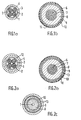
- the cable structure shown in fig. 1a is that of a telecommunication cable of a conventional type.
- This cable comprises, for example, a plurality of conductive wires 1 made of a conductive material such as copper or aluminum, surrounded by an insulating layer 2. All of the conductive wires thus sheathed are surrounded by a conductive metallic shield 3 , forming a screen, which is itself surrounded by a protective layer constituted by a semiconductor polymer 4, ensuring good physical contact with the metal surface 3.
- the space 5 left free between the insulating sheaths 2 and the metal surface 3 can be filled in the conventional way with a sealant.
- the energy transport cable shown in fig. 1b which is also of a known type, comprises, for its part, a strand of conducting wires 6, which is surrounded by a sheath or semiconductive polymer layer 7.
- a sheath or semiconductive polymer layer 7 Around this sheath 7 is arranged an insulating material 8, itself surrounded by a second semiconductor polymer layer 9, surrounded by a layer of conductive metal 10 forming a screen, for example consisting of copper, steel or aluminum.
- the outer belt 11 can itself be constituted by an insulating or semi-conductive polymer sheath.
- US-A-4095039 describes a cable structure in which a sealing layer having semiconductive properties and ensuring perfect sealing is interposed between a metallic screen and a semiconductive polymer layer surrounding a plurality of conductive cables.
- the sealing layer comprises a polyisobutylene rubber, a large amount of carbon black and, if necessary, to lower its viscosity, an oil, in as small an amount as possible.
- the object of the present invention is therefore to produce such structures of electric cables in which a perfect seal is ensured between a metal screen and a semiconductor polymer layer and which ensure a continuous earthing of the cables.
- the subject of the invention is an electrical cable structure of the type comprising at least one screen and at least one semi-conductive polymer layer surrounding at least one conductive cable, characterized in that between said metallic screen and said layer a semiconductive polymer is interposed with a sealing layer with a dynamic viscosity of less than 100,000 centipoises at 20 ° C.
- this sealing layer comprising a semiconductor jelly containing between 50 and 95% by weight of at least one compound of a paraffinic or naphthenic hydrocarbon oil of petroleum, vegetable or synthetic origin, and between 5 and 50% by weight of carbon black and / or graphite, or a powder of at least one metal chosen from the group comprising zinc, copper, and aluminum, or of at least one oxide of one of these metals; in that the resistivity of said sealing layer is less than 40,000 ohms x cm; and in that the resistivity of said semiconductor polymer layer is less than 20,000 ohms x cm.
- metallic screen designates not only a conductive shielding of the type illustrated in figs. 1a and 1b, but also any ply of metallic threads, woven, braided or "guippés", to use the term used in the art.
- the semiconductor and hydrophobic jelly used in accordance with the invention is designated by the references 12 and 13, respectively, in FIGS. 2a or 2b, on which the elements already described with reference to FIGS. 1a and 2a keep the same reference figures.
- This jelly is interposed between the metal screens 3, respectively 10, and the semiconductive polymer sheaths 4, respectively 9.
- Fig. 2c shows a particular application of the cable structure according to the invention, in a low noise coaxial cable.
- the friction of the metal braid against the dielectric is generally the source of triboelectric noise.
- the semiconductor jelly constitutes the sealing layer represented by the reference 13 which is interposed between the semiconductor polymer layer 9 which covers the insulating material 8, and the metal braid represented by the reference 10. This arrangement makes it possible to remove much of the triboelectric noise.
- the introduction of the semiconductor and hydrophobic sealing jelly between the metal screen and the semiconductor polymer layer also makes it possible, thanks to the dielectric properties of this layer, to effectively ensure the radialization of the field in the transport cables. of energy.
- a first advantage of the present invention is linked to the fact that the semiconductor jelly is perfectly compatible with both the metal strip, to which it adheres completely and that it protects from possible traces of moisture or other forms of corrosion of the metal. , than with the semiconductor polymer layer, due to the very nature of its constituents, insofar as these cannot diffuse into the polymer layer and where additives and conductive fillers of the same kind are preferably added than those used in the composition of the jelly.
- a second advantage of the present invention lies in the fact that, given the presence of the semiconductor jelly, the semiconductor polymer layer no longer has to simultaneously provide effective protection of the metal strip and maximum adhesion to the metal : the semiconductor polymer layer can therefore be chosen according to the only mechanical properties required for cable protection, in addition to the desired electrical properties.
- a third advantage of this cable belt structure resides in the fact that the semiconductor jelly ensures, by its fluidity and by its plasticity, in addition to a perfect seal and, therefore, an excellent electrical contact between the semiconductor polymer layer and the metallic screen which surrounds it, whatever the mechanical deformations imposed on the cable, while maintaining effective protection of these elements.
- An additional advantage of the cable belt structure according to the invention finally results from the fact that the fluidity and plasticity properties of the sealing layer are not very susceptible to the effect of temperature since the dynamic viscosity is at 20 °. C, less than 100,000 centipoises and, at 100 ° C, remains between 50,000 and 100,000 centipoises.
- This cable belt structure finally considerably facilitates the operations of connecting the cables during their installation.
- This new type of cable belt structure therefore protects, with increased reliability, the metal screen against corrosion and ensures excellent grounding or excellent radialization of the electric field, while better protecting the cable itself by strengthening its outer sheath.
- a proportion of the order of 50 to 95% by weight of paraffinic hydrocarbon compounds is used or Naphthenics selected to not diffuse at temperatures of the order of 50 ° C or more in polyethylene, polypropylene, polybutylene, polyvinyl chloride or any other cellular insulation material used in the composition of the belt sheath.
- hydrocarbon compounds can be of petroleum, vegetable or synthetic origin, or be composed of mixtures of several of these oils.
- distillation cups or oils and / or petrolatum obtained from the latter are used. Generally, less than 5% of these oils have a boiling point below 350 ° C.
- these hydrocarbon compounds are advantageously constituted by polymers obtained from olefins having three or four carbon atoms, or by mixtures of these.
- synthetic oil cuts having a molecular weight by weight of between 200 and 4000 and, more particularly, between 400 and 1500 are used.
- a conductive filler such as a metal powder or metal oxide, the metal of which may advantageously be zinc, copper or aluminum, or carbon black, is added in a manner known per se. , a mixture of carbon black of varying particle size, or graphite or, finally, a mixture of the latter.
- the proportion of the conductive charge, relative to that of the oil, is determined above all by considerations of resistance. electrical and viscosity of the desired semiconductor and hydrophobic jelly, depending on the conditions of manufacture and use of the electrical cable in the belt from which it will be introduced. This proportion can therefore vary between 5 and 50% by weight of the sealing jelly, depending on the case, and, more particularly, between 5 and 40%.
- a particularly advantageous composition according to the invention is obtained by the use of very conductive carbon blacks of the Ketjen EC or Phillips XE2 type; these blacks, which can be used in a lower concentration than conventional blacks, for the same resistivity, make it possible to obtain compositions which are all the more hydrophobic; the concentration of these blacks is between 5 and 15% by weight, depending on whether they are used alone or not and according to the desired resistivity.
- composition of the jelly one can finally add, without however this addition being necessary for all oils, stabilizing agents, adhesiveness agents such as resins of petroleum origin, thickening agents such as unsaturated polyolefins in proportion which may be between 0 and 20%, and finally metal passivators such as benzotriazoles, substituted or not, or any other substance known per se capable of performing a similar function, in proportion which may be between 0 and 2%, depending on the nature of the oil, of the conductive filler or metal used in the composition of the strip (or armor) of the cable.
- stabilizing agents such as resins of petroleum origin
- thickening agents such as unsaturated polyolefins
- metal passivators such as benzotriazoles, substituted or not, or any other substance known per se capable of performing a similar function, in proportion which may be between 0 and 2%, depending on the nature of the oil, of the conductive filler or metal used in the composition of the strip (or armor) of the cable.
- compositions comprising mainly an ethylene polymer, or a mixture of a homopolymer and an ethylene copolymer. , or a mixture of ethylene copolymer with a propylene monomer, vinyl acetate, ethyl acrylate or any other monomer, in a manner known per se.
- compositions containing more than 70% of high or medium density ethylene or polyethylene compolymer will be used, in order to give this sheath the required rigidity and solidity.
- the polyethylene used may advantageously have a density between 0.90 and 0.95 and a melt index between 0.1 and 2. It is also possible to use any plastic material capable of incorporating the conductive fillers and, in particular, polychloride plasticized vinyl.
- the polymer composition also contains a conductive filler, which will advantageously be of the same nature as that contained by the semiconductor jelly entering the cable belt structure.
- the proportion of this load can also vary between 5% and 45%, depending on the resistivity and robustness that can be expected from this type of sheath and the expected conditions of use of the electric cable. For the purposes of continuous earthing, this proportion will advantageously vary between 8 and 15% by weight.
- the sheaths must finally have good resistance to stress cracking.
- the Applicant has carried out comparative tests between them and cable structures of a conventional type.
- compositions of these cables are listed in Table 1 below:
- the presence of a hydrophobic semiconductor jelly between the metal screen and the semiconductor polymer layer allows this screen and this layer to remain constantly in contact. electric, without the use of any auxiliary earthing of the screen, and without risk of accidental corrosion of the latter as a result of ramification phenomena following imperfect contacts between the screen and the semiconductor layer.
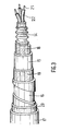
- a first cable D presents the structure illustrated in FIG. 3.
- Around the screen 14 are successively arranged an intermediate semiconductive polymer layer 15, a steel screen 16 arranged in a helix and a semi-conductive external polymer sheath 17.
- the polymer layers and the semiconductor jelly used in the composition of the cable D are produced with formulations identical to those of the cable C previously described.
- Table II below gives the resistance values of the screens in ohms for 50 meters of buried cable of these cables D and D.
- a semiconductive and hydrophobic sealing gel promotes the electrical conductivity between screens and sheaths, while ensuring longitudinal sealing.
- the three constituents of this cable belt are therefore placed in continuous parallel contact, which makes it possible to avoid frequent earthing of the external structure of the cables and to promote the reducing effect.
Landscapes
- Physics & Mathematics (AREA)
- Chemical & Material Sciences (AREA)
- Dispersion Chemistry (AREA)
- Spectroscopy & Molecular Physics (AREA)
- Electromagnetism (AREA)
- Insulated Conductors (AREA)
- Conductive Materials (AREA)
- Compositions Of Macromolecular Compounds (AREA)
Claims (10)
Applications Claiming Priority (2)
| Application Number | Priority Date | Filing Date | Title |
|---|---|---|---|
| FR8310258 | 1983-06-21 | ||
| FR8310258A FR2547945B1 (fr) | 1983-06-21 | 1983-06-21 | Nouvelle structure de cable electrique et ses applications |
Publications (2)
| Publication Number | Publication Date |
|---|---|
| EP0129485A1 EP0129485A1 (de) | 1984-12-27 |
| EP0129485B1 true EP0129485B1 (de) | 1987-06-03 |
Family
ID=9290015
Family Applications (1)
| Application Number | Title | Priority Date | Filing Date |
|---|---|---|---|
| EP84401269A Expired EP0129485B1 (de) | 1983-06-21 | 1984-06-20 | Kabelstruktur und ihre Anwendungen |
Country Status (9)
| Country | Link |
|---|---|
| US (1) | US4621169A (de) |
| EP (1) | EP0129485B1 (de) |
| JP (1) | JPS60501631A (de) |
| KR (1) | KR920000223B1 (de) |
| DE (1) | DE3464100D1 (de) |
| ES (1) | ES533594A0 (de) |
| FR (1) | FR2547945B1 (de) |
| WO (1) | WO1985000245A1 (de) |
| ZA (1) | ZA844682B (de) |
Families Citing this family (70)
| Publication number | Priority date | Publication date | Assignee | Title |
|---|---|---|---|---|
| US4701575A (en) * | 1986-05-27 | 1987-10-20 | Comm/Scope Company | Jacketed cable with powder layer for enhanced corrosion and environmental protection |
| FR2607954B1 (fr) * | 1986-12-04 | 1995-02-24 | Noel Gerard | Procede de protection d'un element d'installation plonge dans un milieu environnant et sensible aux influences electriques, magnetiques et/ou electromagnetiques presentes dans ce milieu |
| US5034719A (en) * | 1989-04-04 | 1991-07-23 | Prestolite Wire Corporation | Radio frequency interference suppression ignition cable having a semiconductive polyolefin conductive core |
| JP2860839B2 (ja) * | 1991-04-10 | 1999-02-24 | 三菱電線工業株式会社 | セパレーター層付電力ケーブル |
| US6380751B2 (en) | 1992-06-11 | 2002-04-30 | Cascade Microtech, Inc. | Wafer probe station having environment control enclosure |
| US5345170A (en) | 1992-06-11 | 1994-09-06 | Cascade Microtech, Inc. | Wafer probe station having integrated guarding, Kelvin connection and shielding systems |
| US6232789B1 (en) | 1997-05-28 | 2001-05-15 | Cascade Microtech, Inc. | Probe holder for low current measurements |
| US5561377A (en) | 1995-04-14 | 1996-10-01 | Cascade Microtech, Inc. | System for evaluating probing networks |
| EP0743656B1 (de) * | 1995-05-19 | 1999-10-06 | Dussek Campbell Limited | Elektrische Energiekabel |
| ATE239068T1 (de) * | 1995-06-07 | 2003-05-15 | Lee County Mosquito Control Di | Schmiermittelzusammensetzungen und verfahren |
| DE19604481A1 (de) * | 1996-02-08 | 1997-08-14 | Asea Brown Boveri | Leitungsabschnitt einer gasisolierten Leitung |
| US5914613A (en) | 1996-08-08 | 1999-06-22 | Cascade Microtech, Inc. | Membrane probing system with local contact scrub |
| FR2754630B1 (fr) | 1996-10-10 | 2000-12-01 | Electricite De France | Procede de fabrication d'un conducteur, ou circuit electrique compense en parasites radioelectriques tels que micro-decharges et conducteur ou circuit correspondant |
| US6002263A (en) | 1997-06-06 | 1999-12-14 | Cascade Microtech, Inc. | Probe station having inner and outer shielding |
| US6256882B1 (en) | 1998-07-14 | 2001-07-10 | Cascade Microtech, Inc. | Membrane probing system |
| US6578264B1 (en) | 1999-06-04 | 2003-06-17 | Cascade Microtech, Inc. | Method for constructing a membrane probe using a depression |
| US6445202B1 (en) | 1999-06-30 | 2002-09-03 | Cascade Microtech, Inc. | Probe station thermal chuck with shielding for capacitive current |
| US6838890B2 (en) | 2000-02-25 | 2005-01-04 | Cascade Microtech, Inc. | Membrane probing system |
| US6914423B2 (en) | 2000-09-05 | 2005-07-05 | Cascade Microtech, Inc. | Probe station |
| US6965226B2 (en) | 2000-09-05 | 2005-11-15 | Cascade Microtech, Inc. | Chuck for holding a device under test |
| DE20114544U1 (de) | 2000-12-04 | 2002-02-21 | Cascade Microtech, Inc., Beaverton, Oreg. | Wafersonde |
| AU2002327490A1 (en) | 2001-08-21 | 2003-06-30 | Cascade Microtech, Inc. | Membrane probing system |
| WO2003020467A1 (en) | 2001-08-31 | 2003-03-13 | Cascade Microtech, Inc. | Optical testing device |
| US6777964B2 (en) | 2002-01-25 | 2004-08-17 | Cascade Microtech, Inc. | Probe station |
| JP2005527823A (ja) | 2002-05-23 | 2005-09-15 | カスケード マイクロテック インコーポレイテッド | デバイスのテスト用プローブ |
| US6847219B1 (en) | 2002-11-08 | 2005-01-25 | Cascade Microtech, Inc. | Probe station with low noise characteristics |
| US6724205B1 (en) | 2002-11-13 | 2004-04-20 | Cascade Microtech, Inc. | Probe for combined signals |
| US7250779B2 (en) | 2002-11-25 | 2007-07-31 | Cascade Microtech, Inc. | Probe station with low inductance path |
| US6861856B2 (en) | 2002-12-13 | 2005-03-01 | Cascade Microtech, Inc. | Guarded tub enclosure |
| US7221172B2 (en) | 2003-05-06 | 2007-05-22 | Cascade Microtech, Inc. | Switched suspended conductor and connection |
| US7057404B2 (en) | 2003-05-23 | 2006-06-06 | Sharp Laboratories Of America, Inc. | Shielded probe for testing a device under test |
| US7492172B2 (en) | 2003-05-23 | 2009-02-17 | Cascade Microtech, Inc. | Chuck for holding a device under test |
| US7250626B2 (en) | 2003-10-22 | 2007-07-31 | Cascade Microtech, Inc. | Probe testing structure |
| US7427868B2 (en) | 2003-12-24 | 2008-09-23 | Cascade Microtech, Inc. | Active wafer probe |
| US7187188B2 (en) | 2003-12-24 | 2007-03-06 | Cascade Microtech, Inc. | Chuck with integrated wafer support |
| EP1754072A2 (de) | 2004-06-07 | 2007-02-21 | CASCADE MICROTECH, INC. (an Oregon corporation) | Thermische optische einspannvorrichtung |
| US7330041B2 (en) | 2004-06-14 | 2008-02-12 | Cascade Microtech, Inc. | Localizing a temperature of a device for testing |
| EP1766426B1 (de) | 2004-07-07 | 2013-09-11 | Cascade Microtech, Inc. | Tastkopf mit einem an der membran aufgehängten fühler |
| DE202005021435U1 (de) | 2004-09-13 | 2008-02-28 | Cascade Microtech, Inc., Beaverton | Doppelseitige Prüfaufbauten |
| US20070102188A1 (en) | 2005-11-01 | 2007-05-10 | Cable Components Group, Llc | High performance support-separators for communications cable supporting low voltage and wireless fidelity applications and providing conductive shielding for alien crosstalk |
| US7256351B2 (en) * | 2005-01-28 | 2007-08-14 | Superior Essex Communications, Lp | Jacket construction having increased flame resistance |
| US7535247B2 (en) | 2005-01-31 | 2009-05-19 | Cascade Microtech, Inc. | Interface for testing semiconductors |
| US7656172B2 (en) | 2005-01-31 | 2010-02-02 | Cascade Microtech, Inc. | System for testing semiconductors |
| US7449899B2 (en) | 2005-06-08 | 2008-11-11 | Cascade Microtech, Inc. | Probe for high frequency signals |
| EP1932003A2 (de) | 2005-06-13 | 2008-06-18 | Cascade Microtech, Inc. | Breitbandige aktiv-passiv-differenzsignalsonde |
| DE202005019690U1 (de) * | 2005-12-16 | 2006-02-16 | Klotz Audio Interface Systems A.I.S. Gmbh | Kabel |
| US9390031B2 (en) * | 2005-12-30 | 2016-07-12 | Intel Corporation | Page coloring to associate memory pages with programs |
| DE112007001399T5 (de) | 2006-06-09 | 2009-05-07 | Cascade Microtech, Inc., Beaverton | Messfühler für differentielle Signale mit integrierter Symmetrieschaltung |
| US7764072B2 (en) | 2006-06-12 | 2010-07-27 | Cascade Microtech, Inc. | Differential signal probing system |
| US7403028B2 (en) | 2006-06-12 | 2008-07-22 | Cascade Microtech, Inc. | Test structure and probe for differential signals |
| US7443186B2 (en) | 2006-06-12 | 2008-10-28 | Cascade Microtech, Inc. | On-wafer test structures for differential signals |
| US7723999B2 (en) | 2006-06-12 | 2010-05-25 | Cascade Microtech, Inc. | Calibration structures for differential signal probing |
| US20080113268A1 (en) * | 2006-10-23 | 2008-05-15 | Buiel Edward R | Recombinant Hybrid Energy Storage Device |
| US7876114B2 (en) | 2007-08-08 | 2011-01-25 | Cascade Microtech, Inc. | Differential waveguide probe |
| US7888957B2 (en) | 2008-10-06 | 2011-02-15 | Cascade Microtech, Inc. | Probing apparatus with impedance optimized interface |
| US8410806B2 (en) | 2008-11-21 | 2013-04-02 | Cascade Microtech, Inc. | Replaceable coupon for a probing apparatus |
| US8319503B2 (en) | 2008-11-24 | 2012-11-27 | Cascade Microtech, Inc. | Test apparatus for measuring a characteristic of a device under test |
| DE102009041067A1 (de) * | 2009-03-21 | 2010-09-30 | Ralf Bauhaus | Kabel |
| EP2312591B1 (de) * | 2009-08-31 | 2020-03-04 | Nexans | Ermüdungsbeständige metallische Feuchtigkeitsabschirmung für ein Unterseestromkabel |
| CN104412337B (zh) * | 2012-03-13 | 2017-03-08 | 电缆元件集团有限责任公司 | 提供通信电缆中的屏蔽的组合物、方法和装置 |
| FR2991808B1 (fr) * | 2012-06-08 | 2015-07-17 | Nexans | Dispositif comprenant une couche piegeuse de charges d'espace |
| FR2995716B1 (fr) * | 2012-09-17 | 2014-09-05 | Silec Cable | Procede de fabrication d'un cable de transport d'energie electrique et cable fabrique par un tel procede |
| US9627100B2 (en) * | 2013-04-24 | 2017-04-18 | Wireco World Group Inc. | High-power low-resistance electromechanical cable |
| JP6261229B2 (ja) * | 2013-07-31 | 2018-01-17 | 株式会社潤工社 | 同軸ケーブル |
| WO2015130692A2 (en) * | 2014-02-25 | 2015-09-03 | Essex Group, Inc. | Insulated winding wire containing semi-conductive layers |
| BR112017019444B1 (pt) * | 2015-03-20 | 2022-01-11 | Prysmian S.P.A. | Cabo de alimentação de múltiplas fases |
| JP2017168279A (ja) * | 2016-03-16 | 2017-09-21 | 住友電気工業株式会社 | 電力ケーブル、電力ケーブルシステム、電力ケーブルシステムの接地方法、および電力ケーブルシステムの構築方法 |
| DE102017210096B4 (de) | 2017-06-16 | 2024-02-08 | Bizlink Industry Germany Gmbh | Datenkabel für explosionsgefährdete Bereiche |
| EP4254434A1 (de) * | 2022-03-31 | 2023-10-04 | Nexans | Elektrisches kabel, das eine deren installation erleichternde oberfläche aufweist |
| WO2024092208A1 (en) * | 2022-10-28 | 2024-05-02 | Delstar Technologies, Inc. | Water swellable semi-conductive tape |
Family Cites Families (10)
| Publication number | Priority date | Publication date | Assignee | Title |
|---|---|---|---|---|
| DE1915061B2 (de) * | 1969-03-25 | 1972-03-23 | Chemische Werke Hüls AG, 4370 Mari | Leitfaehige kunststoffmasse fuer den kabelsektor |
| US3878146A (en) * | 1973-06-04 | 1975-04-15 | Hexcel Corp | Cured epoxy resin compositions useful in the protection of electrical cables |
| US4095039A (en) * | 1976-04-16 | 1978-06-13 | General Cable Corporation | Power cable with improved filling compound |
| GB1484850A (en) * | 1976-06-28 | 1977-09-08 | Gen Cable Corp | Electric cables |
| US4104480A (en) * | 1976-11-05 | 1978-08-01 | General Cable Corporation | Semiconductive filling compound for power cable with improved properties |
| US4190570A (en) * | 1977-05-20 | 1980-02-26 | Witco Chemical Corporation | Cable filler |
| US4324453A (en) * | 1981-02-19 | 1982-04-13 | Siecor Corporation | Filling materials for electrical and light waveguide communications cables |
| FR2505082A1 (fr) * | 1981-04-30 | 1982-11-05 | Cables De Lyon Geoffroy Delore | Materiau de bourrage semi-conducteur pour cable sous-marin, cable comportant ce materiau et procede de fabrication de ce cable |
| FR2508227A1 (fr) * | 1981-06-18 | 1982-12-24 | Cables De Lyon Geoffroy Delore | Cable electromecanique resistant a des temperatures et pressions elevees et son procede de fabrication |
| EP0129617B1 (de) * | 1983-06-13 | 1988-02-03 | Du Pont-Mitsui Polychemicals Co., Ltd. | Halbleitende Verbindungen und dieselben benutzende Drähte und Kabel |
-
1983
- 1983-06-21 FR FR8310258A patent/FR2547945B1/fr not_active Expired
-
1984
- 1984-06-20 ZA ZA844682A patent/ZA844682B/xx unknown
- 1984-06-20 EP EP84401269A patent/EP0129485B1/de not_active Expired
- 1984-06-20 ES ES533594A patent/ES533594A0/es active Granted
- 1984-06-20 DE DE8484401269T patent/DE3464100D1/de not_active Expired
- 1984-06-21 WO PCT/FR1984/000157 patent/WO1985000245A1/fr not_active Ceased
- 1984-06-21 US US06/703,806 patent/US4621169A/en not_active Expired - Lifetime
- 1984-06-21 JP JP59502389A patent/JPS60501631A/ja active Pending
- 1984-06-21 KR KR1019840003594A patent/KR920000223B1/ko not_active Expired
Also Published As
| Publication number | Publication date |
|---|---|
| ZA844682B (en) | 1985-02-27 |
| FR2547945B1 (fr) | 1986-05-02 |
| EP0129485A1 (de) | 1984-12-27 |
| FR2547945A1 (fr) | 1984-12-28 |
| DE3464100D1 (en) | 1987-07-09 |
| US4621169A (en) | 1986-11-04 |
| KR920000223B1 (ko) | 1992-01-10 |
| WO1985000245A1 (fr) | 1985-01-17 |
| ES8601550A1 (es) | 1985-10-16 |
| KR850000741A (ko) | 1985-03-09 |
| ES533594A0 (es) | 1985-10-16 |
| JPS60501631A (ja) | 1985-09-26 |
Similar Documents
| Publication | Publication Date | Title |
|---|---|---|
| EP0129485B1 (de) | Kabelstruktur und ihre Anwendungen | |
| EP2224459B1 (de) | Hochspannungskabel | |
| EP2859633B1 (de) | Vorrichtung mit einer ladungsblockierungsschicht | |
| FR2937041A1 (fr) | Composition semi-conductrice pour cables electriques | |
| GB1583353A (en) | Electric cables | |
| WO2010105972A1 (en) | Medium-voltage cable | |
| KR20180007689A (ko) | 초고압 직류 전력케이블용 중간접속함 및 이를 포함하는 초고압 직류 전력케이블 접속시스템 | |
| EP0644641B1 (de) | Garnitur zum Verbinden eines Energiekabels und damit ausgerüstetes Energiekabel | |
| US6331353B1 (en) | Stranded conductor filling compound and cables using same | |
| EP3398194B1 (de) | Kabel mit einer feuerbeständigen isolierschicht | |
| CA2860786C (fr) | Cable electrique a moyenne ou haute tension | |
| EP2136376A1 (de) | Hochspannungsstromkabel | |
| EP3422366B1 (de) | Kabel, das ein elektrisch leitendes element umfasst, das metallisierte karbonfasern enthält | |
| BE878803A (fr) | Enceinte pour terminaison ou raccord de cables electriques | |
| FR2710183A1 (fr) | Câble d'énergie à rigidité diélectrique améliorée. | |
| EP0644558B2 (de) | Kabelisolierstruktur | |
| EP2498264B1 (de) | Mittel- oder Hochspannungsstromkabel | |
| EP3404673B1 (de) | Feuerbeständiges kable | |
| WO2017153658A1 (fr) | Câble électrique destiné à être enterré | |
| JPS6356645B2 (de) | ||
| EP3671768A1 (de) | Elektrisches kabel, das beständig gegen wasserbäumchen ist | |
| EP3544025A1 (de) | Elektrokabel mit einer leicht abziehbaren polymerschicht | |
| JPH01217803A (ja) | 走水防止電力用電線、ケーブル | |
| JPH0757556A (ja) | 水密性絶縁電線 | |
| FR2629626A1 (fr) | Cable pour courant continu |
Legal Events
| Date | Code | Title | Description |
|---|---|---|---|
| PUAI | Public reference made under article 153(3) epc to a published international application that has entered the european phase |
Free format text: ORIGINAL CODE: 0009012 |
|
| AK | Designated contracting states |
Designated state(s): BE CH DE FR GB IT LI LU NL SE |
|
| 17P | Request for examination filed |
Effective date: 19850511 |
|
| 17Q | First examination report despatched |
Effective date: 19860129 |
|
| D17Q | First examination report despatched (deleted) | ||
| ITF | It: translation for a ep patent filed | ||
| GRAA | (expected) grant |
Free format text: ORIGINAL CODE: 0009210 |
|
| RAP1 | Party data changed (applicant data changed or rights of an application transferred) |
Owner name: ACOME SOCIETE ANONYME DITE: Owner name: COMPAGNIE DE RAFFINAGE ET DE DISTRIBUTION TOTAL F |
|
| AK | Designated contracting states |
Kind code of ref document: B1 Designated state(s): BE CH DE FR GB IT LI LU NL SE |
|
| REF | Corresponds to: |
Ref document number: 3464100 Country of ref document: DE Date of ref document: 19870709 |
|
| PLBE | No opposition filed within time limit |
Free format text: ORIGINAL CODE: 0009261 |
|
| STAA | Information on the status of an ep patent application or granted ep patent |
Free format text: STATUS: NO OPPOSITION FILED WITHIN TIME LIMIT |
|
| 26N | No opposition filed | ||
| ITTA | It: last paid annual fee | ||
| EPTA | Lu: last paid annual fee | ||
| EAL | Se: european patent in force in sweden |
Ref document number: 84401269.0 |
|
| PGFP | Annual fee paid to national office [announced via postgrant information from national office to epo] |
Ref country code: FR Payment date: 19980417 Year of fee payment: 15 |
|
| PGFP | Annual fee paid to national office [announced via postgrant information from national office to epo] |
Ref country code: NL Payment date: 19980518 Year of fee payment: 15 |
|
| PGFP | Annual fee paid to national office [announced via postgrant information from national office to epo] |
Ref country code: GB Payment date: 19980612 Year of fee payment: 15 |
|
| PGFP | Annual fee paid to national office [announced via postgrant information from national office to epo] |
Ref country code: SE Payment date: 19980617 Year of fee payment: 15 Ref country code: DE Payment date: 19980617 Year of fee payment: 15 |
|
| PGFP | Annual fee paid to national office [announced via postgrant information from national office to epo] |
Ref country code: LU Payment date: 19980619 Year of fee payment: 15 |
|
| PGFP | Annual fee paid to national office [announced via postgrant information from national office to epo] |
Ref country code: CH Payment date: 19980701 Year of fee payment: 15 |
|
| PGFP | Annual fee paid to national office [announced via postgrant information from national office to epo] |
Ref country code: BE Payment date: 19980709 Year of fee payment: 15 |
|
| PG25 | Lapsed in a contracting state [announced via postgrant information from national office to epo] |
Ref country code: LU Free format text: LAPSE BECAUSE OF NON-PAYMENT OF DUE FEES Effective date: 19990620 Ref country code: GB Free format text: LAPSE BECAUSE OF NON-PAYMENT OF DUE FEES Effective date: 19990620 |
|
| PG25 | Lapsed in a contracting state [announced via postgrant information from national office to epo] |
Ref country code: SE Free format text: THE PATENT HAS BEEN ANNULLED BY A DECISION OF A NATIONAL AUTHORITY Effective date: 19990629 |
|
| PG25 | Lapsed in a contracting state [announced via postgrant information from national office to epo] |
Ref country code: LI Free format text: LAPSE BECAUSE OF NON-PAYMENT OF DUE FEES Effective date: 19990630 Ref country code: FR Free format text: THE PATENT HAS BEEN ANNULLED BY A DECISION OF A NATIONAL AUTHORITY Effective date: 19990630 Ref country code: CH Free format text: LAPSE BECAUSE OF NON-PAYMENT OF DUE FEES Effective date: 19990630 Ref country code: BE Free format text: LAPSE BECAUSE OF NON-PAYMENT OF DUE FEES Effective date: 19990630 |
|
| BERE | Be: lapsed |
Owner name: ACOME Effective date: 19990630 Owner name: CIE DE RAFFINAGE ET DE DISTRIBUTION TOTAL FRANCE Effective date: 19990630 |
|
| PG25 | Lapsed in a contracting state [announced via postgrant information from national office to epo] |
Ref country code: NL Free format text: LAPSE BECAUSE OF NON-PAYMENT OF DUE FEES Effective date: 20000101 |
|
| GBPC | Gb: european patent ceased through non-payment of renewal fee |
Effective date: 19990620 |
|
| REG | Reference to a national code |
Ref country code: CH Ref legal event code: PL |
|
| EUG | Se: european patent has lapsed |
Ref document number: 84401269.0 |
|
| NLV4 | Nl: lapsed or anulled due to non-payment of the annual fee |
Effective date: 20000101 |
|
| PG25 | Lapsed in a contracting state [announced via postgrant information from national office to epo] |
Ref country code: DE Free format text: LAPSE BECAUSE OF NON-PAYMENT OF DUE FEES Effective date: 20000503 |
|
| REG | Reference to a national code |
Ref country code: FR Ref legal event code: ST |