EP0127895A2 - Mécanisme de positionnement - Google Patents
Mécanisme de positionnement Download PDFInfo
- Publication number
- EP0127895A2 EP0127895A2 EP84106311A EP84106311A EP0127895A2 EP 0127895 A2 EP0127895 A2 EP 0127895A2 EP 84106311 A EP84106311 A EP 84106311A EP 84106311 A EP84106311 A EP 84106311A EP 0127895 A2 EP0127895 A2 EP 0127895A2
- Authority
- EP
- European Patent Office
- Prior art keywords
- links
- base
- attached
- angle
- axis
- Prior art date
- Legal status (The legal status is an assumption and is not a legal conclusion. Google has not performed a legal analysis and makes no representation as to the accuracy of the status listed.)
- Granted
Links
- 230000007246 mechanism Effects 0.000 title claims abstract description 25
- 230000001105 regulatory effect Effects 0.000 claims abstract description 4
- 230000008878 coupling Effects 0.000 description 6
- 238000010168 coupling process Methods 0.000 description 6
- 238000005859 coupling reaction Methods 0.000 description 6
- 238000010276 construction Methods 0.000 description 5
- 230000008859 change Effects 0.000 description 3
- 238000005259 measurement Methods 0.000 description 3
- 238000004519 manufacturing process Methods 0.000 description 2
- 230000001133 acceleration Effects 0.000 description 1
- 230000001276 controlling effect Effects 0.000 description 1
- 238000005520 cutting process Methods 0.000 description 1
- 230000000694 effects Effects 0.000 description 1
- 230000009467 reduction Effects 0.000 description 1
- 230000000717 retained effect Effects 0.000 description 1
- 239000000523 sample Substances 0.000 description 1
Images


Classifications
-
- B—PERFORMING OPERATIONS; TRANSPORTING
- B23—MACHINE TOOLS; METAL-WORKING NOT OTHERWISE PROVIDED FOR
- B23P—METAL-WORKING NOT OTHERWISE PROVIDED FOR; COMBINED OPERATIONS; UNIVERSAL MACHINE TOOLS
- B23P19/00—Machines for simply fitting together or separating metal parts or objects, or metal and non-metal parts, whether or not involving some deformation; Tools or devices therefor so far as not provided for in other classes
-
- B—PERFORMING OPERATIONS; TRANSPORTING
- B23—MACHINE TOOLS; METAL-WORKING NOT OTHERWISE PROVIDED FOR
- B23Q—DETAILS, COMPONENTS, OR ACCESSORIES FOR MACHINE TOOLS, e.g. ARRANGEMENTS FOR COPYING OR CONTROLLING; MACHINE TOOLS IN GENERAL CHARACTERISED BY THE CONSTRUCTION OF PARTICULAR DETAILS OR COMPONENTS; COMBINATIONS OR ASSOCIATIONS OF METAL-WORKING MACHINES, NOT DIRECTED TO A PARTICULAR RESULT
- B23Q1/00—Members which are comprised in the general build-up of a form of machine, particularly relatively large fixed members
- B23Q1/25—Movable or adjustable work or tool supports
- B23Q1/44—Movable or adjustable work or tool supports using particular mechanisms
- B23Q1/50—Movable or adjustable work or tool supports using particular mechanisms with rotating pairs only, the rotating pairs being the first two elements of the mechanism
-
- B—PERFORMING OPERATIONS; TRANSPORTING
- B25—HAND TOOLS; PORTABLE POWER-DRIVEN TOOLS; MANIPULATORS
- B25J—MANIPULATORS; CHAMBERS PROVIDED WITH MANIPULATION DEVICES
- B25J17/00—Joints
- B25J17/02—Wrist joints
- B25J17/0208—Compliance devices
-
- B—PERFORMING OPERATIONS; TRANSPORTING
- B25—HAND TOOLS; PORTABLE POWER-DRIVEN TOOLS; MANIPULATORS
- B25J—MANIPULATORS; CHAMBERS PROVIDED WITH MANIPULATION DEVICES
- B25J17/00—Joints
- B25J17/02—Wrist joints
- B25J17/0258—Two-dimensional joints
- B25J17/0266—Two-dimensional joints comprising more than two actuating or connecting rods
-
- B—PERFORMING OPERATIONS; TRANSPORTING
- B25—HAND TOOLS; PORTABLE POWER-DRIVEN TOOLS; MANIPULATORS
- B25J—MANIPULATORS; CHAMBERS PROVIDED WITH MANIPULATION DEVICES
- B25J17/00—Joints
- B25J17/02—Wrist joints
- B25J17/0258—Two-dimensional joints
- B25J17/0275—Universal joints, e.g. Hooke, Cardan, ball joints
-
- B—PERFORMING OPERATIONS; TRANSPORTING
- B25—HAND TOOLS; PORTABLE POWER-DRIVEN TOOLS; MANIPULATORS
- B25J—MANIPULATORS; CHAMBERS PROVIDED WITH MANIPULATION DEVICES
- B25J9/00—Programme-controlled manipulators
- B25J9/10—Programme-controlled manipulators characterised by positioning means for manipulator elements
- B25J9/106—Programme-controlled manipulators characterised by positioning means for manipulator elements with articulated links
- B25J9/1065—Programme-controlled manipulators characterised by positioning means for manipulator elements with articulated links with parallelograms
- B25J9/107—Programme-controlled manipulators characterised by positioning means for manipulator elements with articulated links with parallelograms of the froglegs type
-
- F—MECHANICAL ENGINEERING; LIGHTING; HEATING; WEAPONS; BLASTING
- F16—ENGINEERING ELEMENTS AND UNITS; GENERAL MEASURES FOR PRODUCING AND MAINTAINING EFFECTIVE FUNCTIONING OF MACHINES OR INSTALLATIONS; THERMAL INSULATION IN GENERAL
- F16M—FRAMES, CASINGS OR BEDS OF ENGINES, MACHINES OR APPARATUS, NOT SPECIFIC TO ENGINES, MACHINES OR APPARATUS PROVIDED FOR ELSEWHERE; STANDS; SUPPORTS
- F16M11/00—Stands or trestles as supports for apparatus or articles placed thereon ; Stands for scientific apparatus such as gravitational force meters
- F16M11/02—Heads
- F16M11/04—Means for attachment of apparatus; Means allowing adjustment of the apparatus relatively to the stand
- F16M11/043—Allowing translations
-
- F—MECHANICAL ENGINEERING; LIGHTING; HEATING; WEAPONS; BLASTING
- F16—ENGINEERING ELEMENTS AND UNITS; GENERAL MEASURES FOR PRODUCING AND MAINTAINING EFFECTIVE FUNCTIONING OF MACHINES OR INSTALLATIONS; THERMAL INSULATION IN GENERAL
- F16M—FRAMES, CASINGS OR BEDS OF ENGINES, MACHINES OR APPARATUS, NOT SPECIFIC TO ENGINES, MACHINES OR APPARATUS PROVIDED FOR ELSEWHERE; STANDS; SUPPORTS
- F16M11/00—Stands or trestles as supports for apparatus or articles placed thereon ; Stands for scientific apparatus such as gravitational force meters
- F16M11/02—Heads
- F16M11/04—Means for attachment of apparatus; Means allowing adjustment of the apparatus relatively to the stand
- F16M11/06—Means for attachment of apparatus; Means allowing adjustment of the apparatus relatively to the stand allowing pivoting
- F16M11/12—Means for attachment of apparatus; Means allowing adjustment of the apparatus relatively to the stand allowing pivoting in more than one direction
- F16M11/121—Means for attachment of apparatus; Means allowing adjustment of the apparatus relatively to the stand allowing pivoting in more than one direction constituted of several dependent joints
-
- F—MECHANICAL ENGINEERING; LIGHTING; HEATING; WEAPONS; BLASTING
- F16—ENGINEERING ELEMENTS AND UNITS; GENERAL MEASURES FOR PRODUCING AND MAINTAINING EFFECTIVE FUNCTIONING OF MACHINES OR INSTALLATIONS; THERMAL INSULATION IN GENERAL
- F16M—FRAMES, CASINGS OR BEDS OF ENGINES, MACHINES OR APPARATUS, NOT SPECIFIC TO ENGINES, MACHINES OR APPARATUS PROVIDED FOR ELSEWHERE; STANDS; SUPPORTS
- F16M11/00—Stands or trestles as supports for apparatus or articles placed thereon ; Stands for scientific apparatus such as gravitational force meters
- F16M11/02—Heads
- F16M11/18—Heads with mechanism for moving the apparatus relatively to the stand
Definitions
- This invention relates to a positioning mechanism for moving and rotating a single structural element, such as a table, tool or a mechanism grasping an object, to a desired position in space and at a desired orientation, and for supporting the same at the desired position and orientation.
- the object of the present invention is to provide a novel mechanism for moving a table having an article placed thereon or secured thereto to any position and orientation in space, and for maintaining the table in the stated position and orientation.
- a table of the type described finds use in supporting parts thereon so that the parts may be assembled automatically, in various automatic measurement operations by having a measurement probe secured thereto, and in many other applications.
- the table can also be used in the handling of an object since it is equipped with a mechanism for grasping the object.
- Tables of this kind include, e.g., a table for securing a workpiece in a machine tool, a table for scientific experiments, and an automatic handling apparatus.
- the conventional practice is to employ an ordinary table such as an XY table for these purposes.
- the six degrees of freedom referred to are linear movement along each of three mutually perpendicular axes, and rotational movement about each of these three axes.
- the six power sources include a first power source for moving the object along the X axis, a second power source for moving both the object and the first power source along the Y axis, a third power source for moving the object, as well as the first and second power sources, along the Z axis, a fourth power source for rotating the object, as well as the first through third power sources, about the X axis, and so on through a sixth power source.
- the second power source is required to have a larger weight and capacity than the first
- that the third power source is required to have a larger weight and capacity than the second, and so on.
- the sixth power source must be capable of bearing the total wieght of the first through fifth power sources, and must have a capacity large enough to transport these other sources through space.
- the sixth power source inevitably is required to be large in size and weight.
- the object of the present invention is to provide a novel positioning mechanism free from the aforementioned disadvantages encountered in the prior art.
- Fig. 1 The example of a prior-art arrangement shown in Fig. 1 is one in which there are but two degrees of freedom in order to simplify the discussion of the problem. However, a configuration having six degrees of freedom may readily be analogized from the discussion that follows.
- a housing 110 has shafts 108, 109 secured thereto in parallel relation, the shafts serving as guides for a second housing 106 adapted to slide therealong.
- a feed screw 107 for moving the second housing 106 has one end thereof coupled to a motor 111.
- the feed screw 107 is driven into rotation to transport the second housing 106 longitudinally of the shafts 108, 109.
- Attached to the second housing 106 for similar translational motion at right angles to the travelling direction of the second housing are parallel shafts 103, 104, a feed screw 102 and a motor 105.
- a table 101 is transported longitudinally of the shafts 103, 104 by the feed screw 102, which is coupled at one end to the motor 105 and rotated thereby.
- an object secured to the table 101 can be moved to any point confined to a limited area in a plane.
- the position of the table can be controlled by an electrical signal by adopting a feedback control system wherein a rotational angle sensor is mounted on each of the motor shafts and outputs from the sensors are applied to servo circuits controlling the respective motor currents.
- a circuit for storing electrical signals is provided and position information indicative of a desired position is stored in the circuit, then the table can be moved automatically to one desired position after another.
- the workpiece can be subjected to turning and cutting operations in two dimensions automatically even if the position of a tool performing the work is fixed.
- a device for grasping and releasing an object can be secured to the table, whereby the object can be carried from one location to another automatically.
- a mechanism capable of moving a single structural element e.g., the table in the illustrated example
- a positioning mechanism capable of moving a single structural element (e.g., the table in the illustrated example) to a desired special position and of supporting the element at that position in the foregoing manner.
- the illustrated arrangement is capable of achieving positioning solely in a predetermined plane. If it is desired to acquire motion in a direction at right angles to both sets of shafts 108, 109; 103, 104; namely in a direction (referred to as the "vertical" direction hereinafter) orthogonal to the plane defined thereby, then a mechanism for transporting a second table in the vertical direction is secured to the table 101 and the second table is used for positioning in this direction. Where it is necessary to change the angular orientation of the tables, mechanisms are similarly attached for rotating the tables through the desired angles.
- the load imposed upon a source of motive power for movement associated with a certain degree of freedom is not merely the weight of the object being moved but includes also the weight of motive power sources for movement associated with the other degrees of freedom as well as the weight of the equipment for supporting these power sources.
- the overall apparatus is therefore large in size and weight.
- the load borne by the motor 111 includes not only the table 101 desired to be moved but also the motor 105, housing 106, shafts 103, 104 and feed screw 102. Accordingly, the load acting upon the motor 111 is extreme. This makes it impossible to achieve rapid acceleration and deceleration and necessitates the use of very large motors. An unfortunate consequence is an overall reduction in travelling speed, a tendency which becomes more pronounced as the degrees of freedom increase.
- the present invention provides a positioning apparatus which is free of the above-described drawbacks.
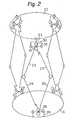
- the purpose of the arrangement shown in Fig. 2 is to move a travelling table 22 accurately to a desired position with respect to a base 21, and to support the table at that position.
- the base 21 and travelling table 22 are coupled together by three pantagraph mechanisms each of which comprises two upper links and two lower links. Since the three pantagraph mechanisms are identical in construction, only one will be described.
- Four links 23, 24, 25, 26 are interconnected to form a quadrilateral in such a manner that two adjoining links are rotatable about a single shaft connecting these two links together. If the angle defined by any two adjoining links is decided, then this will decide the shape of the quadrilateral as well as the length of the diagonals thereof. Changing the three angles defined by the six lower links will change the positions and the shapes of the three quadrilaterals.
- Fig. 3 shows in enlarged form an example of the detailed construction of a portion of the pantagraph where adjoining lower links 24, 26 are interconnected by a shaft 27.
- the connecting shaft 27 is formed to include a shaft 28 orthogonal thereto, the shaft 28 being rotatably supported at both ends thereof by a bracket 29 secured to the base 21.
- a rotary shaft 30 interconnecting the adjoining upper links 23, 25 is formed to include a shaft 31 orthogonal thereto, the shaft 31 being rotatably supported at both ends thereof by a bracket 32.
- the latter is attached to the travelling table 22 so as to be freely rotatable about a shaft 33 orthogonal to both of the shafts 30, 31.
- the lower link 26 is driven by a source of motive power (Fig. 4) in such a manner as to be capable of producing turning effort about the shaft 27.
- the lower link 24 is driven by another source of motive power in such a manner as to be capable of producing turning effort about the shaft 27.
- the lower links 24, 26 are driven in such a manner that the angle formed by the lower link 24 with respect to the shaft 28, as well as the angle formed by the lower link 26 with respect to the shaft 28, can be changed independently of each other.
- pantagraph mechanism has two sources of motive power, so that the overall mechanism, which is composed of three pantagraphs, has a total of six motive power sources.
- Positional control can be achieved by measuring the angle of a driven lower link through adoption of suitable means and feeding back the measured value.
- the travelling table 22 can be fixed in position if the angle of each link driven by the respective source of motive power is fixed by positioning control. This enables the traveling table to be moved to a desired point within a three-dimensional range of allowable movement, and to be supported at that point. The orientation or inclination of the table 22 relative to the base 21 can be changed and the table can be supported at the angle of inclination.
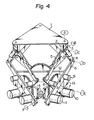
- Fig. 4 includes the sources of motive power not shown in Fig. 2.
- a table 1 is shown to be supported in space.
- a coupling retainer 2 is attached to the table 1 so as to be freely rotatable about an axis A orthogonal to the plane of the table.
- a coupling 3 is retained by the coupling retainer 2 so as to be freely rotatable about an axis B lying parallel to the plane of the table.
- Upper links 4, 5 are attached to the coupling 3 so as to be freely rotatable independently of each other about an axis C orthogonal to the axis B, which is the axis about which the coupling 3 is freely rotatable with respect to the coupling retainer 2.
- the upper link 4 is connected to a lower link 6 so as to be freely rotatable about an axis D, which lies parallel to the axis C.
- the upper link 5 is similarly connected to a lower link 7.
- the lower links 6, 7 are attached to each other so as to be freely rotatable about an axis E, which lies parallel to the axes C and D.
- the axis E occupies a position which is fixed with respect to a gear mounting plate 13.
- a main gear 12 Secured to the gear mounting plate 13 is a main gear 12 which lies perpendicular to the axis E and whose central axis coincides with the axis E.
- a motor 11 secured to the lower link 6 has a shaft to which a gear, not shown, is affixed. The gear meshes with the main gear 12 and undergoes planetary motion about the main gear.
- a potensiometer 9 having a shaft to which a gear, not shown, is affixed. This gear also meshes with the main gear 12 and undergoes planetary motion thereabout.
- a motor 10 secured to the lower link 7 has a shaft to which a gear, not shown, is affixed. This gear meshes with the main gear 12 for planetary motion with respect thereto.
- the lower link 7 has a potentiometer 8 secured thereto.
- a gear, not shown, is secured to the shaft of the potentiometer 8 and meshes with the main gear 12 for planetary motion thereabout.
- the gear mounting plate 13 is supported at one end by a support member 14 and at the other end by a similar support member, not shown, so as to be freely rotatable about an axis F.
- the upper links 4, 5 and lower links 6, 7 thus construct a quadrilateral.
- the distance between the axes E and C will be referred to as the length of the diagonal line of the quadrilateral, and the angle defined by the diagonal line and the axis F will be referred to as the angle of inclination of the diagonal line.
- the motors 10, 11 are supplied with electric power to drive their respective shafts into rotation, thereby changing the angles of the lower links 6, 7 with respect to the main gear 12, as well as the length and angle of inclination of the diagonal line.
- the angle through which the lower link 6 rotates with respect to the main gear 12 is measured by rotation of the potentiometer 9.
- the rotational angle of the lower link 7 with respect to the main gear 12 is measured by rotation of the potensiometer 8.
- the position and orientation of the table 1 in space can be provided with a maximum of six degrees of freedom.
- the six degrees of freedom possessed by the table two of them can be regulated by one of the quadrilateral link mechanisms which, as described above, is capable of having the length of its diagonal line and the inclination angle thereof controlled. Accordingly, if the similarly constructed link mechanisms provide three-point support, then a limitation can be imposed on the total of six degrees of freedom, thereby allowing the position and orientation of the table to be freely adjusted and fixed.
- the table can be made to occupy any position and angle of inclination within a given range, and the table can be fixedly supported at that position and angle.
Landscapes
- Engineering & Computer Science (AREA)
- Mechanical Engineering (AREA)
- General Engineering & Computer Science (AREA)
- Robotics (AREA)
- Machine Tool Units (AREA)
Applications Claiming Priority (4)
| Application Number | Priority Date | Filing Date | Title |
|---|---|---|---|
| JP9920383A JPS59224591A (ja) | 1983-06-02 | 1983-06-02 | 移動テ−ブル機構 |
| JP99203/83 | 1983-06-02 | ||
| JP58106301A JPS59232739A (ja) | 1983-06-13 | 1983-06-13 | 位置決め機構 |
| JP106301/83 | 1983-06-13 |
Publications (3)
| Publication Number | Publication Date |
|---|---|
| EP0127895A2 true EP0127895A2 (fr) | 1984-12-12 |
| EP0127895A3 EP0127895A3 (en) | 1986-12-17 |
| EP0127895B1 EP0127895B1 (fr) | 1990-03-21 |
Family
ID=26440357
Family Applications (1)
| Application Number | Title | Priority Date | Filing Date |
|---|---|---|---|
| EP84106311A Expired EP0127895B1 (fr) | 1983-06-02 | 1984-06-01 | Mécanisme de positionnement |
Country Status (4)
| Country | Link |
|---|---|
| US (1) | US4607578A (fr) |
| EP (1) | EP0127895B1 (fr) |
| CA (1) | CA1255616A (fr) |
| DE (1) | DE3481694D1 (fr) |
Cited By (13)
| Publication number | Priority date | Publication date | Assignee | Title |
|---|---|---|---|---|
| WO1987003528A1 (fr) * | 1985-12-16 | 1987-06-18 | Sogeva S.A. | Dispositif pour le deplacement et le positionnement d'un element dans l'espace |
| EP0263627A1 (fr) * | 1986-09-30 | 1988-04-13 | Dilip Kohli | Robots et dispositif d'actionnement rotatif et linéaire employé dans ces robots |
| EP0494565A1 (fr) * | 1991-01-11 | 1992-07-15 | Ecole Centrale Des Arts Et Manufactures | Dispositif pour le déplacement en translation spatiale d'un élément dans l'espace en particulier pour robot mécanique |
| FR2688437A1 (fr) * | 1992-03-11 | 1993-09-17 | Centre Nat Rech Scient | Manipulateur spatial parallele a six degres de liberte. |
| FR2690372A1 (fr) * | 1992-04-24 | 1993-10-29 | Toyoda Machine Works Ltd | Robot parallèle à bras articulés. |
| EP0760272A1 (fr) * | 1995-07-31 | 1997-03-05 | Hihaisuto Seiko Co Ltd | Mécanisme de positionnement à plusieurs degrés de liberté |
| FR2741421A1 (fr) * | 1995-11-21 | 1997-05-23 | Rivages Productions | Dispositif de support a inclinaison reglable et notamment a conservation de son horizontalite |
| WO1999014018A1 (fr) * | 1997-09-12 | 1999-03-25 | Abb Ab | Dispositif permettant le mouvement relatif de deux elements |
| US6161809A (en) * | 1996-10-25 | 2000-12-19 | Mahy; Laurent | Tilt-adjustable supporting device, in particular maintained in a horizontal position |
| CN102152306A (zh) * | 2011-04-27 | 2011-08-17 | 天津大学 | 杆轮组合式三平一转并联机构 |
| CN102161201A (zh) * | 2011-04-27 | 2011-08-24 | 天津大学 | 上下伸缩式三平一转并联机构 |
| CN102161200A (zh) * | 2011-04-27 | 2011-08-24 | 天津大学 | 平行错动式三平一转并联机构 |
| CN102513996A (zh) * | 2011-12-19 | 2012-06-27 | 天津大学 | 双平行四边形式三平一转并联机构 |
Families Citing this family (28)
| Publication number | Priority date | Publication date | Assignee | Title |
|---|---|---|---|---|
| US4848179A (en) * | 1988-02-16 | 1989-07-18 | Trw Inc. | Flexidigit robotic manipulator |
| US4964062A (en) * | 1988-02-16 | 1990-10-16 | Ubhayakar Shivadev K | Robotic arm systems |
| US5021798A (en) * | 1988-02-16 | 1991-06-04 | Trw Inc. | Antenna with positionable reflector |
| US4919382A (en) * | 1988-09-14 | 1990-04-24 | The United States Of America As Represented By The Secretary Of The Navy | Multi-post yoke gimbal |
| US5129279A (en) * | 1991-02-28 | 1992-07-14 | Rennex Brian G | Flexible robotic limb |
| US5153999A (en) * | 1991-04-12 | 1992-10-13 | Dcm Tech, Inc. | Auto level cradle |
| US5401128A (en) * | 1991-08-26 | 1995-03-28 | Ingersoll Milling Machine Company | Octahedral machine with a hexapodal triangular servostrut section |
| US5349900A (en) * | 1993-01-05 | 1994-09-27 | Rottler Donald B | Dual-axis table assembly |
| US5489089A (en) * | 1994-04-26 | 1996-02-06 | Ohio Northern University | Automatic alignmant vise |
| GB2347883A (en) * | 1999-03-19 | 2000-09-20 | Neil Trevor Smith | Tripod manipulator |
| JP4493767B2 (ja) * | 1999-11-25 | 2010-06-30 | Thk株式会社 | 自在継手 |
| DE10206414A1 (de) * | 2001-03-16 | 2002-10-02 | Siemens Ag | Vorrichtung zur Positionierung eines Werkzeugs innerhalb eines vorgegebenen Arbeitsbereichs |
| US7241070B2 (en) * | 2001-07-13 | 2007-07-10 | Renishaw Plc | Pivot joint |
| US7044553B2 (en) * | 2004-06-22 | 2006-05-16 | Sears Manufacturing Co. | Vehicle seat suspension with omni directional isolator |
| ES2258917B1 (es) * | 2005-02-17 | 2007-12-01 | Fundacion Fatronik | Robot paralelo con cuatro grados de libertad de alta velocidad. |
| US7275332B2 (en) * | 2005-02-22 | 2007-10-02 | Carestream Health, Inc. | Multi-axis positioning apparatus |
| CN100393484C (zh) * | 2006-06-09 | 2008-06-11 | 北京工业大学 | 三平移一转动并联机构 |
| US8291607B2 (en) * | 2009-02-20 | 2012-10-23 | Hill Philip A | Goniometric positioning system |
| AU2010249320A1 (en) * | 2009-05-22 | 2011-12-15 | Vestas Wind Systems A/S | Systems and methods for transporting and assembling segmented wind turbine blades |
| US11353084B2 (en) * | 2013-03-15 | 2022-06-07 | Clearmotion Acquisition I Llc | Rotary actuator driven vibration isolation |
| FR3046451B1 (fr) * | 2016-01-06 | 2018-07-06 | Micro-Controle - Spectra-Physics | Systeme de generation de deplacement d'une plaque de support selon six degres de liberte. |
| US9961989B2 (en) | 2016-03-07 | 2018-05-08 | Marc Stefan Witt | Radial scissor lift table and method |
| US10154729B2 (en) * | 2016-05-10 | 2018-12-18 | Knape & Vogt Manufacturing Company | Articulating ergonomic support arm |
| CN106426111B (zh) * | 2016-11-24 | 2019-03-19 | 天津大学 | 连续回转式四支链三平一转高速并联机械手 |
| CN107965645A (zh) * | 2017-11-17 | 2018-04-27 | 中国航空工业集团公司北京航空精密机械研究所 | 一种六自由度串联平台 |
| WO2021158906A1 (fr) * | 2020-02-07 | 2021-08-12 | Analytical Space, Inc. | Support réglable pour une communication par satellite |
| CN114290023B (zh) * | 2021-12-30 | 2022-11-04 | 哈尔滨工业大学 | 一种航天器六自由度低应力装配装置 |
| CN114766202B (zh) * | 2022-04-14 | 2023-04-21 | 华南农业大学 | 一种九自由度的茶叶采摘机器人 |
Citations (4)
| Publication number | Priority date | Publication date | Assignee | Title |
|---|---|---|---|---|
| US3288421A (en) * | 1965-03-29 | 1966-11-29 | Everett R Peterson | Movable and rotatable top |
| FR1511683A (fr) * | 1964-12-07 | 1968-02-02 | Franklin Institute | Simulateur de mouvement à dispositifs de commande linéaires |
| GB2083795A (en) * | 1980-09-13 | 1982-03-31 | Marconi Co Ltd | Manipulator mechanisms |
| GB2086980A (en) * | 1980-11-12 | 1982-05-19 | Marconi Co Ltd | Universal joints |
Family Cites Families (11)
| Publication number | Priority date | Publication date | Assignee | Title |
|---|---|---|---|---|
| US554516A (en) * | 1896-02-11 | Piano-chair | ||
| US3229941A (en) * | 1962-06-04 | 1966-01-18 | Suliteanu Menahem | Antenna support |
| US3273879A (en) * | 1963-09-13 | 1966-09-20 | Olaf J Floren | Compound sine plate |
| US3215391A (en) * | 1964-06-29 | 1965-11-02 | Collins Radio Co | Positioning device continuous in azimuth and elevation using multiple linear drives |
| US3374977A (en) * | 1966-06-09 | 1968-03-26 | Collins Radio Co | Antenna positioner |
| US3456943A (en) * | 1966-07-27 | 1969-07-22 | Chance Mfg Co Inc | Amusement ride apparatus and method |
| US3419238A (en) * | 1967-06-21 | 1968-12-31 | Air Force Usa | Parallel platform linkages for shock isolation systems |
| US3765631A (en) * | 1971-08-06 | 1973-10-16 | Lord Corp | Resilient gimbal mounting |
| CH598786A5 (en) * | 1975-10-24 | 1978-05-12 | Paul Furrer | Adjustable inclined desk, table or trolley top |
| FR2445754A1 (fr) * | 1979-01-08 | 1980-08-01 | Harmand Pierre | Support inclinable pour objet ou piece a usiner |
| JPS5667709A (en) * | 1979-11-08 | 1981-06-08 | Matsushita Electric Ind Co Ltd | Turning-angle detector |
-
1984
- 1984-06-01 CA CA000455714A patent/CA1255616A/fr not_active Expired
- 1984-06-01 DE DE8484106311T patent/DE3481694D1/de not_active Expired - Fee Related
- 1984-06-01 EP EP84106311A patent/EP0127895B1/fr not_active Expired
- 1984-06-01 US US06/616,085 patent/US4607578A/en not_active Expired - Fee Related
Patent Citations (4)
| Publication number | Priority date | Publication date | Assignee | Title |
|---|---|---|---|---|
| FR1511683A (fr) * | 1964-12-07 | 1968-02-02 | Franklin Institute | Simulateur de mouvement à dispositifs de commande linéaires |
| US3288421A (en) * | 1965-03-29 | 1966-11-29 | Everett R Peterson | Movable and rotatable top |
| GB2083795A (en) * | 1980-09-13 | 1982-03-31 | Marconi Co Ltd | Manipulator mechanisms |
| GB2086980A (en) * | 1980-11-12 | 1982-05-19 | Marconi Co Ltd | Universal joints |
Cited By (20)
| Publication number | Priority date | Publication date | Assignee | Title |
|---|---|---|---|---|
| WO1987003528A1 (fr) * | 1985-12-16 | 1987-06-18 | Sogeva S.A. | Dispositif pour le deplacement et le positionnement d'un element dans l'espace |
| EP0263627A1 (fr) * | 1986-09-30 | 1988-04-13 | Dilip Kohli | Robots et dispositif d'actionnement rotatif et linéaire employé dans ces robots |
| US4806068A (en) * | 1986-09-30 | 1989-02-21 | Dilip Kohli | Rotary linear actuator for use in robotic manipulators |
| EP0494565A1 (fr) * | 1991-01-11 | 1992-07-15 | Ecole Centrale Des Arts Et Manufactures | Dispositif pour le déplacement en translation spatiale d'un élément dans l'espace en particulier pour robot mécanique |
| FR2671505A1 (fr) * | 1991-01-11 | 1992-07-17 | Ecole Centrale Arts Manufactur | Dispositif pour le deplacement en translation spatiale d'un element dans l'espace, en particulier pour robot mecanique. |
| FR2688437A1 (fr) * | 1992-03-11 | 1993-09-17 | Centre Nat Rech Scient | Manipulateur spatial parallele a six degres de liberte. |
| FR2690372A1 (fr) * | 1992-04-24 | 1993-10-29 | Toyoda Machine Works Ltd | Robot parallèle à bras articulés. |
| US5333514A (en) * | 1992-04-24 | 1994-08-02 | Toyoda Koki Kabushiki Kaisha | Parallel robot |
| EP0760272A1 (fr) * | 1995-07-31 | 1997-03-05 | Hihaisuto Seiko Co Ltd | Mécanisme de positionnement à plusieurs degrés de liberté |
| WO1997019291A1 (fr) * | 1995-11-21 | 1997-05-29 | Rivages Productions S.A.R.L. | Dispositif de support a inclinaison reglable et notamment a conservation de son horizontalite |
| FR2741421A1 (fr) * | 1995-11-21 | 1997-05-23 | Rivages Productions | Dispositif de support a inclinaison reglable et notamment a conservation de son horizontalite |
| US6161809A (en) * | 1996-10-25 | 2000-12-19 | Mahy; Laurent | Tilt-adjustable supporting device, in particular maintained in a horizontal position |
| WO1999014018A1 (fr) * | 1997-09-12 | 1999-03-25 | Abb Ab | Dispositif permettant le mouvement relatif de deux elements |
| US6425303B1 (en) | 1997-09-12 | 2002-07-30 | Abb Ab | Device for relative movement of two elements |
| CN102152306A (zh) * | 2011-04-27 | 2011-08-17 | 天津大学 | 杆轮组合式三平一转并联机构 |
| CN102161201A (zh) * | 2011-04-27 | 2011-08-24 | 天津大学 | 上下伸缩式三平一转并联机构 |
| CN102161200A (zh) * | 2011-04-27 | 2011-08-24 | 天津大学 | 平行错动式三平一转并联机构 |
| CN102161200B (zh) * | 2011-04-27 | 2012-05-16 | 天津大学 | 平行错动式三平一转并联机构 |
| CN102161201B (zh) * | 2011-04-27 | 2012-05-16 | 天津大学 | 上下伸缩式三平一转并联机构 |
| CN102513996A (zh) * | 2011-12-19 | 2012-06-27 | 天津大学 | 双平行四边形式三平一转并联机构 |
Also Published As
| Publication number | Publication date |
|---|---|
| CA1255616A (fr) | 1989-06-13 |
| DE3481694D1 (de) | 1990-04-26 |
| EP0127895A3 (en) | 1986-12-17 |
| EP0127895B1 (fr) | 1990-03-21 |
| US4607578A (en) | 1986-08-26 |
Similar Documents
| Publication | Publication Date | Title |
|---|---|---|
| EP0127895B1 (fr) | Mécanisme de positionnement | |
| US6974297B2 (en) | Industrial robot | |
| US5339749A (en) | Table positioning mechanism | |
| US5746565A (en) | Robotic wafer handler | |
| US6099217A (en) | Device for spatially moving a body with three to six degrees of freedom in a controlled manner | |
| US5903125A (en) | Positioning system | |
| US6157157A (en) | Positioning system | |
| US4838515A (en) | Article positioner and method | |
| US5006036A (en) | Portal system | |
| US5611248A (en) | Two-axis robot | |
| US4327596A (en) | Multi-axes positioning system | |
| JPS62181842A (ja) | ロボツトによる組立システムにおける工具台移動装置とワ−クステ−シヨン | |
| JPH0465148A (ja) | 自動ハンドリング装置 | |
| JP2004516153A (ja) | プラットフォームの直動位置決め用装置 | |
| US5165296A (en) | Drive system | |
| US4749330A (en) | Transport mechanism | |
| US5216932A (en) | X-y drive apparatus | |
| US3517624A (en) | Movable table surface and means of positioning same | |
| US4637761A (en) | Automated tool positioning system | |
| GB2085399A (en) | Robotic manipulator | |
| KR100237553B1 (ko) | 3차원상에서 위치 및 자세를 제어하기 위한 병렬기구 구조 | |
| CN110480762B (zh) | 一种模组式三自由度加工机器人 | |
| JPH04348895A (ja) | ワーク搬送用多関節型ロボット | |
| JP2969981B2 (ja) | 2軸出力モジュール及びこれを用いた駆動装置 | |
| US4557663A (en) | Modular, low cost, pogrammable assembly system |
Legal Events
| Date | Code | Title | Description |
|---|---|---|---|
| PUAI | Public reference made under article 153(3) epc to a published international application that has entered the european phase |
Free format text: ORIGINAL CODE: 0009012 |
|
| AK | Designated contracting states |
Designated state(s): DE FR GB NL SE |
|
| PUAL | Search report despatched |
Free format text: ORIGINAL CODE: 0009013 |
|
| AK | Designated contracting states |
Kind code of ref document: A3 Designated state(s): DE FR GB NL SE |
|
| 17P | Request for examination filed |
Effective date: 19870212 |
|
| 17Q | First examination report despatched |
Effective date: 19880408 |
|
| GRAA | (expected) grant |
Free format text: ORIGINAL CODE: 0009210 |
|
| AK | Designated contracting states |
Kind code of ref document: B1 Designated state(s): DE FR GB NL SE |
|
| REF | Corresponds to: |
Ref document number: 3481694 Country of ref document: DE Date of ref document: 19900426 |
|
| ET | Fr: translation filed | ||
| PLBE | No opposition filed within time limit |
Free format text: ORIGINAL CODE: 0009261 |
|
| STAA | Information on the status of an ep patent application or granted ep patent |
Free format text: STATUS: NO OPPOSITION FILED WITHIN TIME LIMIT |
|
| 26N | No opposition filed | ||
| PGFP | Annual fee paid to national office [announced via postgrant information from national office to epo] |
Ref country code: GB Payment date: 19930521 Year of fee payment: 10 |
|
| PGFP | Annual fee paid to national office [announced via postgrant information from national office to epo] |
Ref country code: FR Payment date: 19930609 Year of fee payment: 10 |
|
| PGFP | Annual fee paid to national office [announced via postgrant information from national office to epo] |
Ref country code: SE Payment date: 19930614 Year of fee payment: 10 |
|
| PGFP | Annual fee paid to national office [announced via postgrant information from national office to epo] |
Ref country code: DE Payment date: 19930623 Year of fee payment: 10 |
|
| PGFP | Annual fee paid to national office [announced via postgrant information from national office to epo] |
Ref country code: NL Payment date: 19930630 Year of fee payment: 10 |
|
| PG25 | Lapsed in a contracting state [announced via postgrant information from national office to epo] |
Ref country code: GB Effective date: 19940601 |
|
| PG25 | Lapsed in a contracting state [announced via postgrant information from national office to epo] |
Ref country code: SE Effective date: 19940602 |
|
| PG25 | Lapsed in a contracting state [announced via postgrant information from national office to epo] |
Ref country code: NL Effective date: 19950101 |
|
| GBPC | Gb: european patent ceased through non-payment of renewal fee |
Effective date: 19940601 |
|
| EUG | Se: european patent has lapsed |
Ref document number: 84106311.8 Effective date: 19950110 |
|
| NLV4 | Nl: lapsed or anulled due to non-payment of the annual fee | ||
| PG25 | Lapsed in a contracting state [announced via postgrant information from national office to epo] |
Ref country code: FR Effective date: 19950228 |
|
| PG25 | Lapsed in a contracting state [announced via postgrant information from national office to epo] |
Ref country code: DE Effective date: 19950301 |
|
| EUG | Se: european patent has lapsed |
Ref document number: 84106311.8 |
|
| REG | Reference to a national code |
Ref country code: FR Ref legal event code: ST |