US6157157A - Positioning system - Google Patents
Positioning system Download PDFInfo
- Publication number
- US6157157A US6157157A US09/273,876 US27387699A US6157157A US 6157157 A US6157157 A US 6157157A US 27387699 A US27387699 A US 27387699A US 6157157 A US6157157 A US 6157157A
- Authority
- US
- United States
- Prior art keywords
- axis
- plate
- along
- block
- coupled
- Prior art date
- Legal status (The legal status is an assumption and is not a legal conclusion. Google has not performed a legal analysis and makes no representation as to the accuracy of the status listed.)
- Expired - Lifetime
Links
Images


Classifications
-
- B—PERFORMING OPERATIONS; TRANSPORTING
- B23—MACHINE TOOLS; METAL-WORKING NOT OTHERWISE PROVIDED FOR
- B23Q—DETAILS, COMPONENTS, OR ACCESSORIES FOR MACHINE TOOLS, e.g. ARRANGEMENTS FOR COPYING OR CONTROLLING; MACHINE TOOLS IN GENERAL CHARACTERISED BY THE CONSTRUCTION OF PARTICULAR DETAILS OR COMPONENTS; COMBINATIONS OR ASSOCIATIONS OF METAL-WORKING MACHINES, NOT DIRECTED TO A PARTICULAR RESULT
- B23Q1/00—Members which are comprised in the general build-up of a form of machine, particularly relatively large fixed members
- B23Q1/25—Movable or adjustable work or tool supports
-
- F—MECHANICAL ENGINEERING; LIGHTING; HEATING; WEAPONS; BLASTING
- F16—ENGINEERING ELEMENTS AND UNITS; GENERAL MEASURES FOR PRODUCING AND MAINTAINING EFFECTIVE FUNCTIONING OF MACHINES OR INSTALLATIONS; THERMAL INSULATION IN GENERAL
- F16H—GEARING
- F16H25/00—Gearings comprising primarily only cams, cam-followers and screw-and-nut mechanisms
- F16H25/02—Gearings comprising primarily only cams, cam-followers and screw-and-nut mechanisms the movements of two or more independently moving members being combined into a single movement
-
- B—PERFORMING OPERATIONS; TRANSPORTING
- B23—MACHINE TOOLS; METAL-WORKING NOT OTHERWISE PROVIDED FOR
- B23Q—DETAILS, COMPONENTS, OR ACCESSORIES FOR MACHINE TOOLS, e.g. ARRANGEMENTS FOR COPYING OR CONTROLLING; MACHINE TOOLS IN GENERAL CHARACTERISED BY THE CONSTRUCTION OF PARTICULAR DETAILS OR COMPONENTS; COMBINATIONS OR ASSOCIATIONS OF METAL-WORKING MACHINES, NOT DIRECTED TO A PARTICULAR RESULT
- B23Q1/00—Members which are comprised in the general build-up of a form of machine, particularly relatively large fixed members
- B23Q1/25—Movable or adjustable work or tool supports
- B23Q1/44—Movable or adjustable work or tool supports using particular mechanisms
- B23Q1/48—Movable or adjustable work or tool supports using particular mechanisms with sliding pairs and rotating pairs
- B23Q1/4852—Movable or adjustable work or tool supports using particular mechanisms with sliding pairs and rotating pairs a single sliding pair followed perpendicularly by a single rotating pair
-
- B—PERFORMING OPERATIONS; TRANSPORTING
- B23—MACHINE TOOLS; METAL-WORKING NOT OTHERWISE PROVIDED FOR
- B23Q—DETAILS, COMPONENTS, OR ACCESSORIES FOR MACHINE TOOLS, e.g. ARRANGEMENTS FOR COPYING OR CONTROLLING; MACHINE TOOLS IN GENERAL CHARACTERISED BY THE CONSTRUCTION OF PARTICULAR DETAILS OR COMPONENTS; COMBINATIONS OR ASSOCIATIONS OF METAL-WORKING MACHINES, NOT DIRECTED TO A PARTICULAR RESULT
- B23Q1/00—Members which are comprised in the general build-up of a form of machine, particularly relatively large fixed members
- B23Q1/25—Movable or adjustable work or tool supports
- B23Q1/44—Movable or adjustable work or tool supports using particular mechanisms
- B23Q1/56—Movable or adjustable work or tool supports using particular mechanisms with sliding pairs only, the sliding pairs being the first two elements of the mechanism
- B23Q1/60—Movable or adjustable work or tool supports using particular mechanisms with sliding pairs only, the sliding pairs being the first two elements of the mechanism two sliding pairs only, the sliding pairs being the first two elements of the mechanism
- B23Q1/601—Movable or adjustable work or tool supports using particular mechanisms with sliding pairs only, the sliding pairs being the first two elements of the mechanism two sliding pairs only, the sliding pairs being the first two elements of the mechanism a single sliding pair followed parallelly by a single sliding pair
-
- B—PERFORMING OPERATIONS; TRANSPORTING
- B23—MACHINE TOOLS; METAL-WORKING NOT OTHERWISE PROVIDED FOR
- B23Q—DETAILS, COMPONENTS, OR ACCESSORIES FOR MACHINE TOOLS, e.g. ARRANGEMENTS FOR COPYING OR CONTROLLING; MACHINE TOOLS IN GENERAL CHARACTERISED BY THE CONSTRUCTION OF PARTICULAR DETAILS OR COMPONENTS; COMBINATIONS OR ASSOCIATIONS OF METAL-WORKING MACHINES, NOT DIRECTED TO A PARTICULAR RESULT
- B23Q1/00—Members which are comprised in the general build-up of a form of machine, particularly relatively large fixed members
- B23Q1/25—Movable or adjustable work or tool supports
- B23Q1/44—Movable or adjustable work or tool supports using particular mechanisms
- B23Q1/56—Movable or adjustable work or tool supports using particular mechanisms with sliding pairs only, the sliding pairs being the first two elements of the mechanism
- B23Q1/60—Movable or adjustable work or tool supports using particular mechanisms with sliding pairs only, the sliding pairs being the first two elements of the mechanism two sliding pairs only, the sliding pairs being the first two elements of the mechanism
- B23Q1/62—Movable or adjustable work or tool supports using particular mechanisms with sliding pairs only, the sliding pairs being the first two elements of the mechanism two sliding pairs only, the sliding pairs being the first two elements of the mechanism with perpendicular axes, e.g. cross-slides
- B23Q1/621—Movable or adjustable work or tool supports using particular mechanisms with sliding pairs only, the sliding pairs being the first two elements of the mechanism two sliding pairs only, the sliding pairs being the first two elements of the mechanism with perpendicular axes, e.g. cross-slides a single sliding pair followed perpendicularly by a single sliding pair
-
- G—PHYSICS
- G05—CONTROLLING; REGULATING
- G05B—CONTROL OR REGULATING SYSTEMS IN GENERAL; FUNCTIONAL ELEMENTS OF SUCH SYSTEMS; MONITORING OR TESTING ARRANGEMENTS FOR SUCH SYSTEMS OR ELEMENTS
- G05B19/00—Programme-control systems
- G05B19/02—Programme-control systems electric
- G05B19/18—Numerical control [NC], i.e. automatically operating machines, in particular machine tools, e.g. in a manufacturing environment, so as to execute positioning, movement or co-ordinated operations by means of programme data in numerical form
- G05B19/19—Numerical control [NC], i.e. automatically operating machines, in particular machine tools, e.g. in a manufacturing environment, so as to execute positioning, movement or co-ordinated operations by means of programme data in numerical form characterised by positioning or contouring control systems, e.g. to control position from one programmed point to another or to control movement along a programmed continuous path
- G05B19/39—Numerical control [NC], i.e. automatically operating machines, in particular machine tools, e.g. in a manufacturing environment, so as to execute positioning, movement or co-ordinated operations by means of programme data in numerical form characterised by positioning or contouring control systems, e.g. to control position from one programmed point to another or to control movement along a programmed continuous path using a combination of the means covered by at least two of the preceding sub-groups G05B19/21, G05B19/27, and G05B19/33
-
- G—PHYSICS
- G05—CONTROLLING; REGULATING
- G05B—CONTROL OR REGULATING SYSTEMS IN GENERAL; FUNCTIONAL ELEMENTS OF SUCH SYSTEMS; MONITORING OR TESTING ARRANGEMENTS FOR SUCH SYSTEMS OR ELEMENTS
- G05B2219/00—Program-control systems
- G05B2219/30—Nc systems
- G05B2219/37—Measurements
- G05B2219/37297—Two measurements, on driving motor and on slide or on both sides of motor
-
- G—PHYSICS
- G05—CONTROLLING; REGULATING
- G05B—CONTROL OR REGULATING SYSTEMS IN GENERAL; FUNCTIONAL ELEMENTS OF SUCH SYSTEMS; MONITORING OR TESTING ARRANGEMENTS FOR SUCH SYSTEMS OR ELEMENTS
- G05B2219/00—Program-control systems
- G05B2219/30—Nc systems
- G05B2219/37—Measurements
- G05B2219/37314—Derive position from speed
-
- G—PHYSICS
- G05—CONTROLLING; REGULATING
- G05B—CONTROL OR REGULATING SYSTEMS IN GENERAL; FUNCTIONAL ELEMENTS OF SUCH SYSTEMS; MONITORING OR TESTING ARRANGEMENTS FOR SUCH SYSTEMS OR ELEMENTS
- G05B2219/00—Program-control systems
- G05B2219/30—Nc systems
- G05B2219/42—Servomotor, servo controller kind till VSS
- G05B2219/42074—Position feedback and speed feedback, speed measured with tacho
-
- G—PHYSICS
- G05—CONTROLLING; REGULATING
- G05B—CONTROL OR REGULATING SYSTEMS IN GENERAL; FUNCTIONAL ELEMENTS OF SUCH SYSTEMS; MONITORING OR TESTING ARRANGEMENTS FOR SUCH SYSTEMS OR ELEMENTS
- G05B2219/00—Program-control systems
- G05B2219/30—Nc systems
- G05B2219/49—Nc machine tool, till multiple
- G05B2219/49288—Three linear actuators to position x y table
-
- Y—GENERAL TAGGING OF NEW TECHNOLOGICAL DEVELOPMENTS; GENERAL TAGGING OF CROSS-SECTIONAL TECHNOLOGIES SPANNING OVER SEVERAL SECTIONS OF THE IPC; TECHNICAL SUBJECTS COVERED BY FORMER USPC CROSS-REFERENCE ART COLLECTIONS [XRACs] AND DIGESTS
- Y10—TECHNICAL SUBJECTS COVERED BY FORMER USPC
- Y10T—TECHNICAL SUBJECTS COVERED BY FORMER US CLASSIFICATION
- Y10T74/00—Machine element or mechanism
- Y10T74/20—Control lever and linkage systems
- Y10T74/20012—Multiple controlled elements
- Y10T74/20201—Control moves in two planes
Definitions
- This invention relates to a positioning system, and particularly to a system for positioning equipment, such as a liquid dispenser, with high precision over at least a two dimensional plane.
- Coordinate positioning systems are used to carry instruments along two or three orthogonal axes to desired locations to perform some task, such as liquid dispensing, testing and measuring, placement of components, inspection, or milling. While a number of devices use such a positioning system, the system of the present invention is described for use with a liquid dispensing system that dispenses small quantities of liquid, such as dots of epoxy or an encapsulating liquid, on a printed circuit board. It being understood that embodiments of the present invention are not limited to liquid dispensing systems.
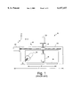
- FIG. 1 is a general representation of a known positioning device 10 for moving a carriage 12 that holds a liquid dispensing device 14 over a workpiece 15.
- Device 10 has a gantry 16 that is moved with a first motor 18 along a y-axis.
- Gantry 16 has a horizontal beam 20 along which a second motor 22 moves carriage 12 along an x-axis.
- Dispensing device 14 is moved along a vertical z-axis with a third motor 24. Movement along any or all of these axes can be accomplished with a lead screw as shown here, with a belt drive, with a rack and pinion, or using linear motors. Note that FIG.
- a vertical beam can be moved along the x-axis, while the vertical beam supports a separate horizontal beam that is movable relative to the vertical beam.
- the device For a given device with a positioning system, the device has a total area that the device takes up (a "footprint"), and a workable area, defined here in the xy-plane, over which the device operates on workpieces 15. To work in this workable area along the x and y axes, the device needs additional space along the x and y axes to accommodate motors and beams, bearings sufficient to hold the carriage firmly, and any other needed components. In a typical system, it is not uncommon along the x-axis for the working area W to be no more than 70% of the total width T of the device (note that FIG. 1 is not to scale).
- the present invention includes a positioning system for moving a device at least in a plane, defined here by orthogonal x and y axes.
- a carriage system can be mounted for movement along x and y axes, preferably with drive mechanisms operated along one axis to create movement in the xy-plane.
- the system has a frame, such as a platform or rails, a plate slidably mounted to the frame to move along a first axis, and a carriage slidably mounted to the plate for movement along a second axis perpendicular to the first axis.
- the system has two blocks, preferably spaced apart for stability, with each block being separately movable along the first axis, and with each block having a rigid arm pivotally connected to the block at one end of the arm and pivotally connected to the carriage at another end of the arm.
- Each block is separately driven along one axis, e.g., with a lead screw or a belt drive, to cause the carriage to move relative to the plate and thereby to cause the arms to push or pull the carriage along the second axis and the plate along the first axis.
- a lead screw or a belt drive to cause the carriage to move relative to the plate and thereby to cause the arms to push or pull the carriage along the second axis and the plate along the first axis.
- Positioning systems in accordance with embodiments of the present invention can be used with a number of different instruments, including a liquid dispensing device, a pick and place machine, machine tools, vision inspection systems, systems utilizing electrical or mechanical probes, and coordinate measuring machines.
- the drive mechanisms are both mounted to operate along the first axis, and therefore, the device can be made very narrow relative to the working area along the second axis, such that the ratio of the width of the working area to the total width of the device can be as much as 90%.
- a y-axis mechanism need not carry or support an x-axis motor and need not include an x-axis driving mechanism as in prior devices; this structure thus avoids use of an x-axis driving mechanism that can create heat and add mass to the moving plate, either of which can adversely affect performance (compare to FIG. 1), and further simplifies the system because there is no requirement to carry x-axis cables and/or belts.
- the present invention provides these benefits while also maintaining good stability because the movable blocks are spaced apart at ends along the x-axis. Another benefit is that the motors, on average, each carry 50% of the load, and therefore can be evenly matched. Other features and advantages will become apparent from the following detailed description, drawings, and claims.
- FIG. 1 is a pictorial side view of a known type of positioning system.
- FIG. 2 is a perspective view of a positioning system according to an embodiment of the present invention.
- FIG. 3 is a cross-sectional view of a trailing arm taken through section lines 3--3 of FIG. 2.
- FIG. 4 is a plan view illustrating movement of the positioning system
- FIG. 5 is a plan view of the carriage, illustrating forces on the carriage during operation.
- FIG. 6 is a block diagram of a control system.
- FIG. 7 is a block diagram of a positioning system in accordance with one embodiment of the present invention.
- FIG. 8 is a diagram illustrating coordinate axes systems used in embodiments of the present invention.
- FIG. 9 is a flow chart illustrating a coordinate transformation method used in embodiments of the present invention.
- FIG. 10 is a block diagram of a positioning system in accordance with one embodiment of the present invention.
- FIG. 2 is a perspective view of a positioning system 40 according to the present invention (shown upside-down to better illustrate the components).
- Positioning system 40 has a first rail 42 and a parallel second rail 44 with respective first and second elongated bearings 46, 48 oriented in parallel along a y-axis and spaced apart along the perpendicular x-axis.
- Extending across the first and second rails 42, 44 is a plate 50 that is slidably mounted to rails 42, 44 and movable along bearings 46, 48 with blocks 52, 54 rigidly mounted at each end of plate 50.
- Bearings in addition to bearings 46 and 48 may be used to provide additional stiffness.
- Plate 50 has two elongated bearings 56, 58 extending in parallel along the x-axis and on a side 57 of plate 50 that faces away from rails 42, 44.
- a carriage 60 is slidably mounted to plate 50 for movement over bearings 56, 58 along the x-axis. Although in this illustrative embodiment, two bearings 56 and 58 are used, only one bearing, or more than two bearings could be used.
- Carriage 60 supports a mechanism for performing work on a workpiece 64, such as a liquid dispenser, movable along the z-axis with a motor and a belt or a lead screw (not shown).
- First and second driven nut blocks 66, 68 are mounted over rails 42, 44 and are slidably movable along the y-axis over bearings 46, 48. Each nut block 66, 68 can be separately driven with respective lead screws 70, 72 and motors 74, 76. In FIG. 2, motors 74, 76 are shown located at the back end of the gantry. These motors can also be located at the front end of the gantry, at the opposite end of the lead screws from the location shown in FIG. 2.
- Carriage 60 is connected to each nut block 66, 68 with respective rigid trailing arms 80, 82 that are pivotally connected at one end to one of the nut blocks and pivotally connected at another end to carriage 60.
- the carriage has a C-shaped end 84 with two vertically oriented bearings extending from a top portion 86 to a bottom portion 88 of end 84.
- Each nut block also has a vertically oriented bearing for pivotal connection to one of the trailing arms.
- the trailing arms are secured to the bearings on the nut blocks.
- trailing arms 80, 82 are preferably shaped as vertically oriented I-beams to resist deflections along the z-axis. Trailing arms 80, 82, and also plate 50 and carriage 60, should be made of a light-weight and stiff material, such as aluminum, titanium, or magnesium.
- first nut block 66 on the left side is spaced slightly further from plate 50 along the y-axis than is second nut block 68.
- first nut block 66 is drawn closer to movable plate 50 to a position 66' and second nut block 68 is moved further away from plate 50 to a position 68', and therefore trailing arms 80, 82 move to positions 80' and 82'.
- the trailing arms can move over a range of angles relative to the x and y axes, and the combination of these varying angled movements can be used for controllable two-dimensional movement.
- y-axis movement of plate 50 can be achieved by moving nut blocks 66, 68 an equal amount at the same time along the y-axis.
- the x-axis movement can be combined with y-axis movement by appropriately moving the first and second nut blocks. For example, if each block is moved in the same direction with one block being moved a little more than the other, the carriage will have y-axis movement and also some x-axis movement; or if one block is moved and the other is not, there will be both x-axis and y-axis movement. While the movement in the system according to the present invention is more complex than prior systems because the movement is non-linear, such movement can be programmed and then calculated with a processor using standard trigonometric calculations.
- FIG. 4 also illustrates an important advantage of the system according to the present invention.
- the total width T of the system is not much wider than the width of the working area W, such that a ratio W/T can be as much as 90%.
- the x-axis width T need only exceed working area W by an amount equal to about one-half the width of carriage 60 on each side.
- both arms could be connected to a single pivot point, e.g., with a knuckling arrangement
- a force will be directed at an angle into first point 90 and will be directed at an angle away from second pivot point 92. If the movement is solely along the x-axis, the net magnitude of the y-components of the vectors should cancel out, leaving only an x-component, but nonetheless causing a clockwise moment because pivot points 90, 92 are spaced apart.
- a center of gravity 94 of carriage 60 is spaced from pivot points 90, 92, a counter-clockwise rotational moment is introduced with the rightward movement of the carriage.
- the distance dx between the pivot points and the distance dy between pivot points 90, 92 and center of gravity 94 can be optimized with mathematical calculations; the optimization can be performed in one of a number of different ways, e.g., so that the average clockwise and counter-clockwise moments are minimized over a given range of motion, or to minimize the net peak moment for the entire range of motion of carriage 60. This arrangement reduces yaw, while the orientations of the stiff trailing arms reduce pitch and roll in the carriage.
- a programmable controller 100 for controlling the functions of the system in accordance with one embodiment of the present invention.
- the controller 100 is implemented using a personal computer with an Intel Pentium® processor running a version of the Microsoft Windows® NT operating system.
- Controller 100 provides signals to motors 74, 76 to cause the motors to move the nut blocks as indicated in FIG. 4; controls a z-axis motor 102 to cause the motor to move vertically along the z-axis along with a pump 104 for dispensing liquid; and controls pump 104 to dispense liquid as desired.
- the controller can be programmed to control workpieces other than the pump 104, such as a gripping tool, a machining tool, a vision system, electrical and mechanical probes, gauges and touch probes.
- controller 100 receives signals from rotary encoders 106, 108 and from linear encoders 110, 112.
- Each rotary encoder is mounted in one of motors 74, 76 and provides data to the controller based on the amount of rotation of the motor, thus translating into y-axis movement by the nut blocks.
- One of the linear encoders is mounted along the y-axis to sense y-axis movement and position of plate 50, and the other linear encoder is mounted on plate 50 to sense movement and position of carriage 60 relative to plate 50 along the x-axis.
- the encoders are used to provide feedback signals to control the motors.
- the linear encoders are used to close a positional control loop, while the rotary encoders are used to close a velocity control loop, so that the velocity of movement, as well as the position of the head, is precisely controlled.
- the controller 100 receives signals from rotary encoders 106, 108 and from three linear encoders 110, 112 and 114. As in the previously described embodiment, each of the rotary encoders 106 and 108 is used to close the velocity control loop, and the three linear encoders are used to control the position control loop.
- each of the linear encoders 110, 112 and 114 is mounted on the plate 50.
- Linear encoder 110 is used to sense movement and position of the carriage 60 relative to the plate 50 along the x-axis.
- Linear encoders 112 and 114 are mounted on opposite ends of the plate 50 and are used to sense y-axis movement and position of the plate 50.
- Two encoders are used to determine y-axis position to account for any yaw errors introduced in the plate.
- the actual y-axis position of the workpiece 64 is determined by interpolating between the two y-axis positions based on the x-axis position.
- FIG. 7 shows the positioning system 40 and the controller 100 in block diagram form.
- the controller 100 includes a motion control card 120 that receives x and y target position signals generated within the controller based on user input or a pre-programmed task.
- the motion control card provides output signals that drive torque mode amplifiers 122 that in turn drive motors 74 and 76.
- the motion control card is implemented using a Delta Tau PMAC2 Ultralight Controller available from Delta Tau Data Systems, Inc., Northridge, Calif.
- motors 74 and 76 are respectively identified as motors A and B, and the position of nutblock 66 along lead screw 70 is identified as "a” and the position of nutblock 68 along lead screw 72 is identified as "b".
- the x/y position of the workpiece 64 is tranlatable to a unique a/b position of the nutblocks, and thus, the a and b positions define a coordinate system identified herein as the a/b coordinate system.
- Typical inputs to the motion control card, as well as the feedback signals from the linear encoders 110, 112 and 114 are expressed in terms of the x/y coordinate system, while the motor control signals generated by the motion control card are in terms of the a/b coordinate system.
- the controller 100 must provide a transformation between the x/y coordinate system and the a/b coordinate system.
- the origin of the x-axis is defined as the midpoint of the carriage 60; the origin of the y-axis is defined as the furthest position, in the y-direction, from the motors 74 and 76 at which the workpiece may be positioned; the origin of the a-axis is defined as the position of the bearing on nutblock 66 when the workpiece is positioned at the x and y origins; and the origin of the b-axis is defined as the position of the bearing on nutblock 68 when the workpiece is positioned at the x and y origins.
- the distance along the x-axis from the center of lead screw 70 to pivot point 90 when the workpiece is at the origin of the x-axis is defined as Xa 0 ;
- the distance along the x-axis from the center of lead screw 72 to pivot point 92 when the workpiece is at the origin of the x-axis is defined as Xb 0 ;
- the distance along the y-axis from the bearing on nutblock 66 to the workpiece when the workpiece is at the origin of the y-axis is equal to Ya 0 ;
- the distance along the y-axis from the bearing on nutblock 68 to the workpiece when the workpiece is at the origin of the y-axis is equal to Ya 0 .
- the a-axis value for a given x-axis value and y-axis value is determined as follows.
- an x-axis value is provided, and in step 220, the x-axis value is added to Xa 0 .
- the result obtained in step 220 is squared, and in step 240, the result of step 230 is subtracted from the square of length of trailing arm 80.
- the square root of the result of step 240 is taken in step 250, and in step 260, Ya 0 is subtracted from the result of step 250.
- the y-axis value is added to the result of step 260 providing the a-axis value in step 280.
- the b-axis value for a given x-axis value and y-axis value is determined as follows.
- the x-axis value is provided, and in step 320, the x-axis value is subtracted from Xb 0 .
- the result obtained in step 320 is squared, and in step 340, the result of step 330 is subtracted from the square of the length of the trailing arm 82. Then, the square root of the result of step 340 is taken in step 350, and in step 360, Ya 0 is subtracted from the result of step 350.
- step 370 the y-axis value is added to the result of step 360, providing the b-axis value in step 380.
- steps other than those specifically described above may be used to transform the x and y values to corresponding a and b values.
- the motion control card 120 provides motor control signals to motors 74 and 76.
- the motion control card includes a transformation block 124, a trajectory generator 126 and a PID control block 128.
- the transformation block 124 provides transformation of the x and y input values to a and b values as described above.
- the trajectory generator generates a number of position and velocity values defining a trajectory from a present a/b position to a desired a/b position.
- the values generated by the trajectory generator are used by the PID control block in conjunction with feedback information from the encoders to position the head to the target position.
- the functional blocks contained within the motion control card may be implemented using software, hardware, or a combination of hardware and software.
- Positional feedback information from encoders 110, 112 and 114 are input into a yaw correction algorithm block 130 from which the x and y positional feedback values are output.
- the x value output from block 130 is equal to the x value input to block 130.
- the y value output from block 130 is calculated, as described above, by interpolating the values from encoders 112 and 114 based on the x value from encoder 110. In embodiments requiring less accuracy, or in which the yaw error of the carriage is insignificant, and in which only one y encoder is used, the yaw correction block may not be used.
- the x and y values output from the yaw correction block are input to a transformation block 132, which is similar to transformation block 124 and generates a and b output values.
- the a and b output values are input into the PID control block 128, where they are compared with the values generated by the trajectory generator to produce the output motor control signals.
- the embodiment of the invention shown in FIG. 7 is most useful for applications in which the workpiece is moved from a first position to a second position without a required path from the first position to the second position.
- the trajectory generator is programmed to provide the most efficient path from the first position to the second position using the a/b coordinate system.
- the most efficient path is typically a "linear path". However, a linear path generated using the a/b coordinate system may not correspond to a straight line in the x/y coordinate system.
- FIG. 10 For applications requiring that specific paths be followed (i.e., lines, arcs, circles), it is preferred that the embodiment of the invention shown in FIG. 10 be utilized.
- the embodiment shown in FIG. 10 is identical to the embodiment shown in FIG. 7 except that the relative placement of the coordinate transform block 124 and the trajectory generator 126 have been reversed. This allows the trajectory generator to generate trajectories based on the x/y coordinate system rather than based on the a/b coordinate system.
- the system shown in FIG. 10 does place an extra burden on the transformation block 124 since, for each x/y position entered, coordinate transformation must be performed for a number of positions, as required by the trajectory generator, rather than for just one position, as in the system of FIG. 7.
- a dispensing system utilizes one of the positioning systems described above, and the workpiece comprises a liquid dispenser that is used to dispense liquid on printed circuit boards for one of a number of purposes, such as to dispense small dots of epoxy liquid on the circuit board; to provide an encapsulating material over a die on a circuit board for chip-on-board mounting; or to dispense a liquid underfill material around an electronic component spaced slightly above a circuit board for wicking under the component.
- the types of material used and the methods of operation are different for these dispensing applications, and therefore different dispensers would be used for performing these different functions, however, all of these functions could be performed using embodiments of the positioning system described above.
- a number of circuit boards are processed so that dots of liquid are dispensed.
- the locations for the dots are entered into the system and provided to the controller.
- the controller uses an optimizing function to decide the order in which the dots are to be dispensed, typically to reduce the amount of travel of the dispenser in the xy-plane.
- Boards are brought to the system with a conveyor system.
- the controller moves the carriage and dispenser to a desired location in the xy-plane, activates the z-axis motor to lower the dispenser to the circuit board, activates the dispenser to cause the dispenser to dispense a small quantity of liquid at that location, and causes the z-axis motor to move away from the circuit board.
- the carriage is then moved to another position in the xy-plane.
- a pick and place machine utilizes one of the positioning systems described above, and the workpiece comprises a vacuum pick-up tool or gripper.
- the vacuum pick-up tool or gripper is positioned over a component to be picked up, the component is picked up by the gripper, and the gripper and component are moved using the positioning system to a predetermined position over a substrate, such as a circuit board, where the component is placed on the circuit board.
- a machining tool utilizes one of the positioning systems described above, and the workpiece comprises a tool for performing an operation on a product.
- the product is loaded into the machine, and the positioning system positions the tool at predetermined positions on the product to perform the operation.
- the tool may be a milling spindle for performing a milling operation.
- a vision inspection system utilizes one of the positioning systems described above, and the workpiece comprises a camera, a lens, and/or an illumination system.
- the camera may be positioned over one or more objects loaded into the device for inspecting or aligning the objects.
- an electrical and/or mechanical inspection system utilizes one of the positioning systems described above, and the workpiece comprises one or more electrical and/or mechanical probes.
- the probes may be positioned over a product and specific points on the product may be mechanically or electrically tested using the probes.
- a coordinate measuring machine may utilize one of the positioning systems to position a gauge probe or touch probe for the purpose of gathering dimensional information about an object.
- two or more of the positioning systems described above may be incorporated in one apparatus for positioning a number of different workpieces.
- One example of such an apparatus is a multiple head dispensing system for dispensing material on one or more substrates.
- a multiple head dispensing system a number of substrates may be dispensed upon in parallel to increase the throughput of the machine.
- the positioning systems described above are particularly suited for such a multiple head system because of the high working area to total width ratio provided by these positioning systems.
- workpieces have been described as being positioned below the gantry system, however, in alternate embodiments, the workpiece may be disposed above the gantry.
- a product to be dispensed upon could be coupled to the gantry system and positioned as required by the gantry system beneath a fixed dispensing system or beneath a dispensing system positionable by a second gantry system.
Abstract
Description
Claims (19)
Priority Applications (1)
| Application Number | Priority Date | Filing Date | Title |
|---|---|---|---|
| US09/273,876 US6157157A (en) | 1997-02-06 | 1999-03-22 | Positioning system |
Applications Claiming Priority (3)
| Application Number | Priority Date | Filing Date | Title |
|---|---|---|---|
| US08/796,236 US5903125A (en) | 1997-02-06 | 1997-02-06 | Positioning system |
| US08/967,682 US5886494A (en) | 1997-02-06 | 1997-11-10 | Positioning system |
| US09/273,876 US6157157A (en) | 1997-02-06 | 1999-03-22 | Positioning system |
Related Parent Applications (1)
| Application Number | Title | Priority Date | Filing Date |
|---|---|---|---|
| US08/967,682 Continuation US5886494A (en) | 1997-02-06 | 1997-11-10 | Positioning system |
Publications (1)
| Publication Number | Publication Date |
|---|---|
| US6157157A true US6157157A (en) | 2000-12-05 |
Family
ID=27121713
Family Applications (3)
| Application Number | Title | Priority Date | Filing Date |
|---|---|---|---|
| US08/967,682 Expired - Lifetime US5886494A (en) | 1997-02-06 | 1997-11-10 | Positioning system |
| US09/203,253 Expired - Lifetime US6025689A (en) | 1997-02-06 | 1998-12-01 | Positioning system |
| US09/273,876 Expired - Lifetime US6157157A (en) | 1997-02-06 | 1999-03-22 | Positioning system |
Family Applications Before (2)
| Application Number | Title | Priority Date | Filing Date |
|---|---|---|---|
| US08/967,682 Expired - Lifetime US5886494A (en) | 1997-02-06 | 1997-11-10 | Positioning system |
| US09/203,253 Expired - Lifetime US6025689A (en) | 1997-02-06 | 1998-12-01 | Positioning system |
Country Status (7)
| Country | Link |
|---|---|
| US (3) | US5886494A (en) |
| EP (1) | EP0958102A1 (en) |
| JP (1) | JP2001511237A (en) |
| KR (1) | KR20000070860A (en) |
| CA (1) | CA2279888A1 (en) |
| TW (1) | TW384250B (en) |
| WO (1) | WO1998034756A1 (en) |
Cited By (36)
| Publication number | Priority date | Publication date | Assignee | Title |
|---|---|---|---|---|
| US6328510B1 (en) * | 1997-10-20 | 2001-12-11 | HüLLER HILLE GMBH | Machine tool for triaxial machining of work pieces |
| EP1223485A2 (en) * | 2000-12-26 | 2002-07-17 | Matsushita Electric Industrial Co., Ltd. | Positioning-controlling apparatus and positioning-controlling method, and part-mounting equipment and part-mounting method |
| EP1228838A1 (en) * | 2001-02-06 | 2002-08-07 | Bleicher, Fritz, Dipl.-Ing. Dr.techn. | Kinematical device for moving a carrier |
| US20030049088A1 (en) * | 2001-09-11 | 2003-03-13 | Gerald Stengele | Machine tool |
| US6647632B2 (en) * | 2001-02-05 | 2003-11-18 | Hitachi Kokusai Electric Inc. | Position measuring apparatus |
| US6694627B2 (en) * | 1998-11-26 | 2004-02-24 | Hitachi Via Mechanics, Ltd. | Printed circuit board processing machine |
| US20040180606A1 (en) * | 2003-03-04 | 2004-09-16 | Fanuc Ltd | Synchronous control device |
| US20040177520A1 (en) * | 2003-01-22 | 2004-09-16 | Nsk Ltd. | Positioning apparatus |
| US20040267475A1 (en) * | 2003-06-27 | 2004-12-30 | Thomas Puchtler | Method for determining actual states of a number of adjusting elements |
| US20050081783A1 (en) * | 2003-10-07 | 2005-04-21 | Korea University | Apparatus for painting traffic marks on road surface |
| US20050100457A1 (en) * | 2000-01-26 | 2005-05-12 | Dl Technology, Llc | System and method for control of fluid dispense pump |
| US20050225901A1 (en) * | 2004-04-09 | 2005-10-13 | Mitutoyo Corporation | Slider device and measuring instrument |
| US6957783B1 (en) | 1999-01-26 | 2005-10-25 | Dl Technology Llc | Dispense tip with vented outlets |
| US6983867B1 (en) | 2002-04-29 | 2006-01-10 | Dl Technology Llc | Fluid dispense pump with drip prevention mechanism and method for controlling same |
| US20060179670A1 (en) * | 2005-02-15 | 2006-08-17 | Columbia Marking Tools | Apparatus and method for controlling a programmable marking scribe |
| US20070170140A1 (en) * | 2006-01-24 | 2007-07-26 | Asm Technology Singapore Pte Ltd | Gantry positioning system |
| US7331482B1 (en) | 2003-03-28 | 2008-02-19 | Dl Technology, Llc | Dispense pump with heated pump housing and heated material reservoir |
| US20080043252A1 (en) * | 2006-06-27 | 2008-02-21 | Parlour Noel S | Internal and external measuring device |
| USRE40539E1 (en) | 1999-11-08 | 2008-10-14 | Dl Technology Llc | Fluid pump and cartridge |
| US20090048699A1 (en) * | 2006-01-11 | 2009-02-19 | Dirk Jahn | System and Method for Detecting a Geometry of a Workpiece |
| US20090165580A1 (en) * | 2008-01-02 | 2009-07-02 | Fisher Lance K | Gantry position tracking using redundant position sensors |
| US7744022B1 (en) | 1999-01-26 | 2010-06-29 | Dl Technology, Llc | Fluid dispense tips |
| US20120006140A1 (en) * | 2009-05-05 | 2012-01-12 | Chung Yuan Christian University | Three-link toggle type positioning platform |
| US8690084B1 (en) | 2000-01-26 | 2014-04-08 | Dl Technology Llc | Fluid dispense tips |
| US8707559B1 (en) | 2007-02-20 | 2014-04-29 | Dl Technology, Llc | Material dispense tips and methods for manufacturing the same |
| US8864055B2 (en) | 2009-05-01 | 2014-10-21 | Dl Technology, Llc | Material dispense tips and methods for forming the same |
| US9057642B2 (en) | 2012-12-03 | 2015-06-16 | Illinois Tool Works Inc. | Method and apparatus for calibrating a dispenser |
| US9144818B2 (en) | 2013-03-13 | 2015-09-29 | Illinois Tool Works Inc. | Method and apparatus for dispensing a viscous material on a substrate |
| US9357686B2 (en) | 2013-11-14 | 2016-05-31 | Illinois Tool Works Inc. | Dispensing apparatus having substrate inverter system and clamping system, and method for dispensing a viscous material on a substrate |
| US9374905B2 (en) | 2013-09-30 | 2016-06-21 | Illinois Tool Works Inc. | Method and apparatus for automatically adjusting dispensing units of a dispenser |
| US9411779B2 (en) | 2012-09-28 | 2016-08-09 | Illinois Tool Works Inc. | Method of dispensing material based on edge detection |
| US9475078B2 (en) | 2012-10-29 | 2016-10-25 | Illinois Tool Works Inc. | Automated multiple head cleaner for a dispensing system and related method |
| US9662675B2 (en) | 2014-07-31 | 2017-05-30 | Illinois Tool Works Inc. | External inverter system for variable substrate thickness and method for rotating a substrate |
| US20190264786A1 (en) * | 2016-07-21 | 2019-08-29 | Florian Valentin ILE | Device for the Angular Positioning of a Shaft |
| US11370596B1 (en) | 2012-02-24 | 2022-06-28 | DL Technology, LLC. | Micro-volume dispense pump systems and methods |
| US11746656B1 (en) | 2019-05-13 | 2023-09-05 | DL Technology, LLC. | Micro-volume dispense pump systems and methods |
Families Citing this family (36)
| Publication number | Priority date | Publication date | Assignee | Title |
|---|---|---|---|---|
| DE3813740A1 (en) * | 1988-04-23 | 1989-11-02 | Vorwerk Co Interholding | FABRIC FOR PRODUCING A COMPONENT |
| US6412328B1 (en) | 1996-10-25 | 2002-07-02 | Speedline Technologies, Inc. | Method and apparatus for measuring the size of drops of a viscous material dispensed from a dispensing system |
| US6007631A (en) * | 1997-11-10 | 1999-12-28 | Speedline Technologies, Inc. | Multiple head dispensing system and method |
| US6214117B1 (en) | 1998-03-02 | 2001-04-10 | Speedline Technologies, Inc. | Dispensing system and method |
| JPH11351857A (en) * | 1998-06-08 | 1999-12-24 | Kuroda Precision Ind Ltd | Method and apparatus for measurement of surface shape of thin plate |
| US6324933B1 (en) * | 1999-10-06 | 2001-12-04 | Agere Systems Guardian Corp. | Planar movable stage mechanism |
| ES2161184B1 (en) * | 1999-12-28 | 2002-07-01 | Consejo Superior Investigacion | A DEVICE OF A WORKING ELEMENT WITH TWO DEGREES OF MOBILITY. |
| WO2001054469A1 (en) * | 2000-01-17 | 2001-07-26 | Matsushita Electric Industrial Co., Ltd. | Positioning control method and positioning control device, and electronic part mounting device using this |
| US6352005B1 (en) * | 2000-04-06 | 2002-03-05 | Industrial Technology Reseach Institute | Two screws double-stroke and screw differential-motion mechanism applied in standard mechanical interface |
| US7065892B2 (en) * | 2001-03-19 | 2006-06-27 | Veeco Instruments Inc. | Method and apparatus for calibrating a vision system to a parts handling device |
| US6983547B2 (en) * | 2001-03-19 | 2006-01-10 | Veeco Instruments Inc. | Goniometer |
| US20030048448A1 (en) * | 2001-03-19 | 2003-03-13 | Fleming Timothy J. | Automated apparatus for testing optical filters |
| US6688458B2 (en) | 2001-10-09 | 2004-02-10 | Speedline Technologies, Inc. | System and method for controlling a conveyor system configuration to accommodate different size substrates |
| DE10203011B4 (en) * | 2002-01-26 | 2005-04-28 | Fip Forschungsinstitut Fuer Pr | Machine tool with a tool parallel kinematics |
| US6823595B1 (en) * | 2002-05-03 | 2004-11-30 | Ronald C Bellavich | Table top X-Y carriage for use with quilting frame |
| US6732442B2 (en) * | 2002-07-15 | 2004-05-11 | Taiwan Semiconductor Manufacturing Co., Ltd | Precise mechanism for load port adjustment |
| US7114261B1 (en) * | 2002-12-31 | 2006-10-03 | Accu-Scribe, Llc | Apparatus for shaping a tile to conform to a contour |
| US6932280B2 (en) * | 2003-05-02 | 2005-08-23 | Speedline Technologies, Inc. | Adjustable needle foot for dispensing system |
| DE102004020996A1 (en) * | 2004-04-19 | 2005-11-03 | Carl Zeiss Industrielle Messtechnik Gmbh | Coordinate measuring device for the metrological determination of a coordinate on a measured object |
| SE527899C2 (en) * | 2004-12-15 | 2006-07-04 | Hexagon Metrology Ab | Coordinate measuring machine with mutually movable legs |
| JP4478584B2 (en) * | 2005-01-17 | 2010-06-09 | 株式会社ミツトヨ | Position control device, measuring device and processing device |
| DE102005003322B3 (en) * | 2005-01-18 | 2006-08-03 | Carl Zeiss Industrielle Messtechnik Gmbh | Method for determining a spatial coordinate of a measuring point on a measuring object and corresponding coordinate measuring machine |
| WO2006095767A1 (en) | 2005-03-09 | 2006-09-14 | Ihi Corporation | Jig |
| US7898204B2 (en) * | 2007-01-05 | 2011-03-01 | Active Precision, Inc. | High-speed substrate manipulator |
| US7812424B2 (en) * | 2007-12-21 | 2010-10-12 | Infineon Technologies Ag | Moisture barrier capacitors in semiconductor components |
| KR101449011B1 (en) * | 2007-12-24 | 2014-10-13 | 두산인프라코어 주식회사 | Cabin tilting apparatus for construction machinery |
| WO2010127824A1 (en) * | 2009-05-05 | 2010-11-11 | Basf Se | Device for aligning a surface of at least one object |
| PE20110872A1 (en) * | 2010-04-05 | 2011-12-30 | Manyari Jorge Alfonso Jesus Vallejo | BLACKBOARD THAT DESCRIBES OR REPRESENTS REALITY IN ITS FOUR DIMENSIONS, UNIVERSAL GRAPHER AND INSTRUMENT FOR LEARNING AND SCIENTIFIC MEASUREMENT |
| DE102010024623B4 (en) * | 2010-06-22 | 2020-01-16 | Hesse Gmbh | Precision machine tool |
| US8794610B2 (en) * | 2011-09-20 | 2014-08-05 | Mitutoyo Corporation | Two-dimension precision transfer equipment, three-dimension precision transfer equipment, and coordinate measuring machine |
| CN203249609U (en) * | 2013-03-26 | 2013-10-23 | 鸿准精密模具(昆山)有限公司 | Dimension test device |
| US9707584B2 (en) | 2014-07-09 | 2017-07-18 | Nordson Corporation | Dual applicator fluid dispensing methods and systems |
| KR101740146B1 (en) * | 2015-10-30 | 2017-05-26 | 주식회사 프로텍 | Pump Position Feedback Type Dispenser and Dispensing Method |
| US11121115B2 (en) * | 2018-09-20 | 2021-09-14 | Asm Technology Singapore Pte Ltd. | Y-theta table for semiconductor equipment |
| TWI721885B (en) * | 2020-05-14 | 2021-03-11 | 雲云科技股份有限公司 | Visible-light-image physiological monitoring system with thermal detecting assistance |
| KR102344957B1 (en) * | 2020-06-05 | 2021-12-30 | 박진우 | Auxiliary shaft for machine tools |
Citations (16)
| Publication number | Priority date | Publication date | Assignee | Title |
|---|---|---|---|---|
| FR2398937A1 (en) * | 1977-07-25 | 1979-02-23 | Lectra Systemes Sa | DEVICE FOR DRIVING AND MOVING A BEAM BASED ON TWO GUIDE RAILS AND ONE OR MORE TROLLEYS ASSOCIATED WITH THE BEAM |
| US4176455A (en) * | 1977-02-24 | 1979-12-04 | Copeland Thomas M | Plotting apparatus |
| FR2621715A1 (en) * | 1987-10-13 | 1989-04-14 | Ensait | MECHANICAL SCANNING DEVICE |
| US4838515A (en) * | 1987-05-18 | 1989-06-13 | Teledyne, Inc. | Article positioner and method |
| US4979093A (en) * | 1987-07-16 | 1990-12-18 | Cavro Scientific Instruments | XYZ positioner |
| US5092021A (en) * | 1990-01-23 | 1992-03-03 | Mikron S.A. | Intermittently rotary workpiece-holding table for working and assembly |
| US5097577A (en) * | 1990-01-12 | 1992-03-24 | Mikron S.A. | Machine with intermittently rotary workpiece-holding table for working and assembly of high-precision pieces |
| EP0508130A1 (en) * | 1991-03-12 | 1992-10-14 | TACCON COSTRUZIONI MECANICHE s.d.F. di A.GIRONI & C. | Servocontrolled axis manipulator with programmable spraying heads |
| DE4234675A1 (en) * | 1991-10-17 | 1993-04-22 | Ken Yanagisawa | TWO-DIMENSIONAL DRIVE SYSTEM |
| US5213559A (en) * | 1991-05-31 | 1993-05-25 | Mikron S.P.A. Bologna | Apparatus for changing blanks and tool automatically in a gear cutting machine |
| US5378282A (en) * | 1993-06-28 | 1995-01-03 | Pollard; Willard L. | Robotic tool manipulating apparatus |
| US5421695A (en) * | 1992-09-04 | 1995-06-06 | Fujitsu Limited | Transfer apparatus and method |
| US5440943A (en) * | 1993-09-15 | 1995-08-15 | Intest Corporation | Electronic test head manipulator |
| US5486151A (en) * | 1991-09-19 | 1996-01-23 | Mikron S. A. Agno | Machining center for machining a workpiece by means of at least two interchangeable tools |
| EP0700733A1 (en) * | 1994-09-10 | 1996-03-13 | INDA INDUSTRIEAUSRÜSTUNGEN GmbH | Apparatus for cleaning and/or deburring of workpieces by liquid jetting |
| US5568189A (en) * | 1994-06-21 | 1996-10-22 | Kneller; Paul J. | Aerial support platform mechanism with five axes of motion |
Family Cites Families (4)
| Publication number | Priority date | Publication date | Assignee | Title |
|---|---|---|---|---|
| US4132937A (en) * | 1976-10-18 | 1979-01-02 | Unimation, Inc. | Programmable manipulator with dynamic feedback apparatus for stabilization |
| JPS5988279A (en) * | 1982-10-15 | 1984-05-22 | 新明和工業株式会社 | Device for converting coordinate of robot with joint |
| US4835710A (en) * | 1987-07-17 | 1989-05-30 | Cincinnati Milacron Inc. | Method of moving and orienting a tool along a curved path |
| JP3626265B2 (en) * | 1995-12-18 | 2005-03-02 | 本田技研工業株式会社 | Machine Tools |
-
1997
- 1997-11-10 US US08/967,682 patent/US5886494A/en not_active Expired - Lifetime
-
1998
- 1998-02-05 KR KR1019997007125A patent/KR20000070860A/en not_active Application Discontinuation
- 1998-02-05 JP JP53483998A patent/JP2001511237A/en not_active Ceased
- 1998-02-05 CA CA002279888A patent/CA2279888A1/en not_active Abandoned
- 1998-02-05 WO PCT/US1998/002071 patent/WO1998034756A1/en not_active Application Discontinuation
- 1998-02-05 EP EP98904882A patent/EP0958102A1/en not_active Withdrawn
- 1998-02-06 TW TW087101573A patent/TW384250B/en not_active IP Right Cessation
- 1998-12-01 US US09/203,253 patent/US6025689A/en not_active Expired - Lifetime
-
1999
- 1999-03-22 US US09/273,876 patent/US6157157A/en not_active Expired - Lifetime
Patent Citations (16)
| Publication number | Priority date | Publication date | Assignee | Title |
|---|---|---|---|---|
| US4176455A (en) * | 1977-02-24 | 1979-12-04 | Copeland Thomas M | Plotting apparatus |
| FR2398937A1 (en) * | 1977-07-25 | 1979-02-23 | Lectra Systemes Sa | DEVICE FOR DRIVING AND MOVING A BEAM BASED ON TWO GUIDE RAILS AND ONE OR MORE TROLLEYS ASSOCIATED WITH THE BEAM |
| US4838515A (en) * | 1987-05-18 | 1989-06-13 | Teledyne, Inc. | Article positioner and method |
| US4979093A (en) * | 1987-07-16 | 1990-12-18 | Cavro Scientific Instruments | XYZ positioner |
| FR2621715A1 (en) * | 1987-10-13 | 1989-04-14 | Ensait | MECHANICAL SCANNING DEVICE |
| US5097577A (en) * | 1990-01-12 | 1992-03-24 | Mikron S.A. | Machine with intermittently rotary workpiece-holding table for working and assembly of high-precision pieces |
| US5092021A (en) * | 1990-01-23 | 1992-03-03 | Mikron S.A. | Intermittently rotary workpiece-holding table for working and assembly |
| EP0508130A1 (en) * | 1991-03-12 | 1992-10-14 | TACCON COSTRUZIONI MECANICHE s.d.F. di A.GIRONI & C. | Servocontrolled axis manipulator with programmable spraying heads |
| US5213559A (en) * | 1991-05-31 | 1993-05-25 | Mikron S.P.A. Bologna | Apparatus for changing blanks and tool automatically in a gear cutting machine |
| US5486151A (en) * | 1991-09-19 | 1996-01-23 | Mikron S. A. Agno | Machining center for machining a workpiece by means of at least two interchangeable tools |
| DE4234675A1 (en) * | 1991-10-17 | 1993-04-22 | Ken Yanagisawa | TWO-DIMENSIONAL DRIVE SYSTEM |
| US5421695A (en) * | 1992-09-04 | 1995-06-06 | Fujitsu Limited | Transfer apparatus and method |
| US5378282A (en) * | 1993-06-28 | 1995-01-03 | Pollard; Willard L. | Robotic tool manipulating apparatus |
| US5440943A (en) * | 1993-09-15 | 1995-08-15 | Intest Corporation | Electronic test head manipulator |
| US5568189A (en) * | 1994-06-21 | 1996-10-22 | Kneller; Paul J. | Aerial support platform mechanism with five axes of motion |
| EP0700733A1 (en) * | 1994-09-10 | 1996-03-13 | INDA INDUSTRIEAUSRÜSTUNGEN GmbH | Apparatus for cleaning and/or deburring of workpieces by liquid jetting |
Non-Patent Citations (6)
| Title |
|---|
| Cooke, Arthur, et al. Advanced reconfigurable machine for flexible fabrication. 1995 North AmericanConference on Smart Structures and Materials , San Diego, CA, Feb. 26 Mar. 3, 1996. * |
| Cooke, Arthur, et al. Advanced reconfigurable machine for flexible fabrication. 1995 North AmericanConference on Smart Structures and Materials, San Diego, CA, Feb. 26-Mar. 3, 1996. |
| Hexel Corporation brochure "Hexel's Hexapod Solutions", Portsmouth, NH 03801. |
| Hexel Corporation brochure Hexel s Hexapod Solutions , Portsmouth, NH 03801. * |
| Ing, et al. "The Hexapod Principle" Laboratory for Machine Tools and Production Engineering at Aachen University of Technology. |
| Ing, et al. The Hexapod Principle Laboratory for Machine Tools and Production Engineering at Aachen University of Technology. * |
Cited By (89)
| Publication number | Priority date | Publication date | Assignee | Title |
|---|---|---|---|---|
| US6328510B1 (en) * | 1997-10-20 | 2001-12-11 | HüLLER HILLE GMBH | Machine tool for triaxial machining of work pieces |
| US6694627B2 (en) * | 1998-11-26 | 2004-02-24 | Hitachi Via Mechanics, Ltd. | Printed circuit board processing machine |
| US7762480B1 (en) | 1999-01-26 | 2010-07-27 | DL Technology, LLC. | Dispense tip with vented outlets |
| US7178745B1 (en) | 1999-01-26 | 2007-02-20 | Dl Technology, Llc | Dispense tip with vented outlets |
| US9180482B1 (en) | 1999-01-26 | 2015-11-10 | DL Technology, LLC. | Fluid dispense tips |
| US8480015B1 (en) | 1999-01-26 | 2013-07-09 | Dl Technology, Llc | Fluid dispense tips |
| US9833807B2 (en) | 1999-01-26 | 2017-12-05 | DL Technology, LLC. | Fluid dispense tips |
| US6957783B1 (en) | 1999-01-26 | 2005-10-25 | Dl Technology Llc | Dispense tip with vented outlets |
| US8056833B1 (en) | 1999-01-26 | 2011-11-15 | Dl Technology, Llc | Dispense tip with vented outlets |
| US7744022B1 (en) | 1999-01-26 | 2010-06-29 | Dl Technology, Llc | Fluid dispense tips |
| US9228582B1 (en) | 1999-11-08 | 2016-01-05 | DL Technology, LLC. | Fluid pump and cartridge |
| US7905945B1 (en) | 1999-11-08 | 2011-03-15 | DL Technology, LLC. | Fluid dispensing system having vacuum unit and method of drawing a vacuum in a fluid dispensing system |
| US8197582B1 (en) | 1999-11-08 | 2012-06-12 | DL Technology, LLC. | Fluid dispensing system having vacuum unit |
| US7448857B1 (en) | 1999-11-08 | 2008-11-11 | Dl Technology, Llc | Fluid pump and cartridge |
| USRE40539E1 (en) | 1999-11-08 | 2008-10-14 | Dl Technology Llc | Fluid pump and cartridge |
| US9242770B2 (en) | 2000-01-26 | 2016-01-26 | Dl Technology, Llc | Fluid dispense tips |
| US20050100457A1 (en) * | 2000-01-26 | 2005-05-12 | Dl Technology, Llc | System and method for control of fluid dispense pump |
| US6892959B1 (en) | 2000-01-26 | 2005-05-17 | Dl Technology Llc | System and method for control of fluid dispense pump |
| US9573156B1 (en) | 2000-01-26 | 2017-02-21 | Dl Technology, Llc | Fluid dispense tips |
| US7000853B2 (en) | 2000-01-26 | 2006-02-21 | Dl Technology, Llc | System and method for control of fluid dispense pump |
| US8690084B1 (en) | 2000-01-26 | 2014-04-08 | Dl Technology Llc | Fluid dispense tips |
| EP1223485A3 (en) * | 2000-12-26 | 2005-02-09 | Matsushita Electric Industrial Co., Ltd. | Positioning-controlling apparatus and positioning-controlling method, and part-mounting equipment and part-mounting method |
| EP1223485A2 (en) * | 2000-12-26 | 2002-07-17 | Matsushita Electric Industrial Co., Ltd. | Positioning-controlling apparatus and positioning-controlling method, and part-mounting equipment and part-mounting method |
| US6741055B2 (en) * | 2000-12-26 | 2004-05-25 | Matsushita Electric Industrial Co., Ltd. | Positioning-controlling apparatus and positioning-controlling method, and part-mounting equipment and part-mounting method |
| US6647632B2 (en) * | 2001-02-05 | 2003-11-18 | Hitachi Kokusai Electric Inc. | Position measuring apparatus |
| EP1228838A1 (en) * | 2001-02-06 | 2002-08-07 | Bleicher, Fritz, Dipl.-Ing. Dr.techn. | Kinematical device for moving a carrier |
| US6761518B2 (en) * | 2001-09-11 | 2004-07-13 | HüLLER HILLE GMBH | Machine tool |
| US20030049088A1 (en) * | 2001-09-11 | 2003-03-13 | Gerald Stengele | Machine tool |
| US10814344B1 (en) | 2002-04-29 | 2020-10-27 | DL Technology, LLC. | Fluid dispense pump with drip prevention mechanism and method for controlling same |
| US9108215B1 (en) | 2002-04-29 | 2015-08-18 | Dl Technology, Llc | Fluid dispense pump with drip prevention mechanism and method for controlling same |
| US6983867B1 (en) | 2002-04-29 | 2006-01-10 | Dl Technology Llc | Fluid dispense pump with drip prevention mechanism and method for controlling same |
| US8220669B1 (en) | 2002-04-29 | 2012-07-17 | Dl Technology, Llc | Fluid dispense pump with drip prevention mechanism and method for controlling same |
| US9833808B1 (en) | 2002-04-29 | 2017-12-05 | Dl Technology, Llc | Fluid dispense pump with drip prevention mechanism and method for controlling same |
| US11364517B1 (en) | 2002-04-29 | 2022-06-21 | DL Technology, LLC. | Fluid dispense pump with drip prevention mechanism and method for controlling same |
| US7694857B1 (en) | 2002-04-29 | 2010-04-13 | Dl Technology, Llc | Fluid dispense pump with drip prevention mechanism and method for controlling same |
| US8701946B1 (en) | 2002-04-29 | 2014-04-22 | Dl Technology, Llc | Fluid dispense pump with drip prevention mechanism and method for controlling same |
| US7152331B2 (en) * | 2003-01-22 | 2006-12-26 | Nsk Ltd. | Positioning apparatus |
| US20040177520A1 (en) * | 2003-01-22 | 2004-09-16 | Nsk Ltd. | Positioning apparatus |
| US20040180606A1 (en) * | 2003-03-04 | 2004-09-16 | Fanuc Ltd | Synchronous control device |
| US7183739B2 (en) * | 2003-03-04 | 2007-02-27 | Fanuc Ltd | Synchronous control device |
| US7331482B1 (en) | 2003-03-28 | 2008-02-19 | Dl Technology, Llc | Dispense pump with heated pump housing and heated material reservoir |
| US20040267475A1 (en) * | 2003-06-27 | 2004-12-30 | Thomas Puchtler | Method for determining actual states of a number of adjusting elements |
| US7212945B2 (en) * | 2003-06-27 | 2007-05-01 | Siemens Aktiengesellschaft | Method for determining actual states of a number of adjusting elements |
| US20050081783A1 (en) * | 2003-10-07 | 2005-04-21 | Korea University | Apparatus for painting traffic marks on road surface |
| US7294204B2 (en) * | 2003-10-07 | 2007-11-13 | Korea Joongang Hak Wonco., Ltd | Apparatus for painting traffic marks on road surface |
| US7249420B2 (en) * | 2004-04-09 | 2007-07-31 | Mitutoyo Corporation | Slider device and measuring instrument |
| US20050225901A1 (en) * | 2004-04-09 | 2005-10-13 | Mitutoyo Corporation | Slider device and measuring instrument |
| US20060179670A1 (en) * | 2005-02-15 | 2006-08-17 | Columbia Marking Tools | Apparatus and method for controlling a programmable marking scribe |
| US7191529B2 (en) * | 2005-02-15 | 2007-03-20 | Columbia Marking Tools | Apparatus and method for controlling a programmable marking scribe |
| US20090048699A1 (en) * | 2006-01-11 | 2009-02-19 | Dirk Jahn | System and Method for Detecting a Geometry of a Workpiece |
| US8109395B2 (en) * | 2006-01-24 | 2012-02-07 | Asm Technology Singapore Pte Ltd | Gantry positioning system |
| US20070170140A1 (en) * | 2006-01-24 | 2007-07-26 | Asm Technology Singapore Pte Ltd | Gantry positioning system |
| US7440120B2 (en) | 2006-06-27 | 2008-10-21 | Barbara E. Parlour | Internal and external measuring device |
| US20080043252A1 (en) * | 2006-06-27 | 2008-02-21 | Parlour Noel S | Internal and external measuring device |
| US8707559B1 (en) | 2007-02-20 | 2014-04-29 | Dl Technology, Llc | Material dispense tips and methods for manufacturing the same |
| US10583454B1 (en) | 2007-02-20 | 2020-03-10 | Dl Technology, Llc | Material dispense tip |
| US11648581B1 (en) | 2007-02-20 | 2023-05-16 | DL Technology, LLC. | Method for manufacturing a material dispense tip |
| US9486830B1 (en) | 2007-02-20 | 2016-11-08 | DL Technology, LLC. | Method for manufacturing a material dispense tip |
| US11292025B1 (en) | 2007-02-20 | 2022-04-05 | DL Technology, LLC. | Material dispense tips and methods for manufacturing the same |
| US8116909B2 (en) | 2008-01-02 | 2012-02-14 | Cyberoptics Corporation | Gantry position tracking using redundant position sensors |
| WO2009088863A3 (en) * | 2008-01-02 | 2009-09-17 | Cyberoptics Corporation | Gantry position tracking using redundant position sensors |
| WO2009088863A2 (en) * | 2008-01-02 | 2009-07-16 | Cyberoptics Corporation | Gantry position tracking using redundant position sensors |
| US20090165580A1 (en) * | 2008-01-02 | 2009-07-02 | Fisher Lance K | Gantry position tracking using redundant position sensors |
| US11420225B1 (en) | 2009-05-01 | 2022-08-23 | DL Technology, LLC. | Material dispense tips and methods for forming the same |
| US9272303B1 (en) | 2009-05-01 | 2016-03-01 | Dl Technology, Llc | Material dispense tips and methods for forming the same |
| US10105729B1 (en) | 2009-05-01 | 2018-10-23 | DL Technology, LLC. | Material dispense tips and methods for forming the same |
| US10722914B1 (en) | 2009-05-01 | 2020-07-28 | DL Technology, LLC. | Material dispense tips and methods for forming the same |
| US11738364B1 (en) | 2009-05-01 | 2023-08-29 | DL Technology, LLC. | Material dispense tips and methods for forming the same |
| US8864055B2 (en) | 2009-05-01 | 2014-10-21 | Dl Technology, Llc | Material dispense tips and methods for forming the same |
| US20120006140A1 (en) * | 2009-05-05 | 2012-01-12 | Chung Yuan Christian University | Three-link toggle type positioning platform |
| US8272334B2 (en) * | 2009-05-05 | 2012-09-25 | Chung Yuan Christian University | Three-link toggle type positioning platform |
| US11370596B1 (en) | 2012-02-24 | 2022-06-28 | DL Technology, LLC. | Micro-volume dispense pump systems and methods |
| US9779494B2 (en) | 2012-09-28 | 2017-10-03 | Illinois Tool Works Inc. | Apparatus for dispensing material based on edge detection |
| US9411779B2 (en) | 2012-09-28 | 2016-08-09 | Illinois Tool Works Inc. | Method of dispensing material based on edge detection |
| US10010900B2 (en) | 2012-10-29 | 2018-07-03 | Illinois Tool Works Inc. | Automated multiple head cleaner for a dispensing system and related method |
| US9475078B2 (en) | 2012-10-29 | 2016-10-25 | Illinois Tool Works Inc. | Automated multiple head cleaner for a dispensing system and related method |
| US9057642B2 (en) | 2012-12-03 | 2015-06-16 | Illinois Tool Works Inc. | Method and apparatus for calibrating a dispenser |
| US9636699B2 (en) | 2013-03-13 | 2017-05-02 | Illinois Tool Works Inc. | Method and apparatus for dispensing a viscous material on a substrate |
| US9144818B2 (en) | 2013-03-13 | 2015-09-29 | Illinois Tool Works Inc. | Method and apparatus for dispensing a viscous material on a substrate |
| US9775250B2 (en) | 2013-09-30 | 2017-09-26 | Illinois Tool Works Inc. | Method and apparatus for automatically adjusting dispensing units of a dispenser |
| US10966323B2 (en) | 2013-09-30 | 2021-03-30 | Illinois Tool Works Inc. | Method and apparatus for automatically adjusting dispensing units of a dispenser |
| US9374905B2 (en) | 2013-09-30 | 2016-06-21 | Illinois Tool Works Inc. | Method and apparatus for automatically adjusting dispensing units of a dispenser |
| US11395410B2 (en) | 2013-09-30 | 2022-07-19 | Illinois Tool Works Inc. | Method and apparatus for automatically adjusting dispensing units of a dispenser |
| US10244634B2 (en) | 2013-09-30 | 2019-03-26 | Illinois Tool Works Inc. | Method and apparatus for automatically adjusting dispensing units of a dispenser |
| US9936585B2 (en) | 2013-09-30 | 2018-04-03 | Illinois Tool Works Inc. | Method and apparatus for automatically adjusting dispensing units of a dispenser |
| US9357686B2 (en) | 2013-11-14 | 2016-05-31 | Illinois Tool Works Inc. | Dispensing apparatus having substrate inverter system and clamping system, and method for dispensing a viscous material on a substrate |
| US9662675B2 (en) | 2014-07-31 | 2017-05-30 | Illinois Tool Works Inc. | External inverter system for variable substrate thickness and method for rotating a substrate |
| US20190264786A1 (en) * | 2016-07-21 | 2019-08-29 | Florian Valentin ILE | Device for the Angular Positioning of a Shaft |
| US11746656B1 (en) | 2019-05-13 | 2023-09-05 | DL Technology, LLC. | Micro-volume dispense pump systems and methods |
Also Published As
| Publication number | Publication date |
|---|---|
| JP2001511237A (en) | 2001-08-07 |
| EP0958102A1 (en) | 1999-11-24 |
| TW384250B (en) | 2000-03-11 |
| CA2279888A1 (en) | 1998-08-13 |
| KR20000070860A (en) | 2000-11-25 |
| US5886494A (en) | 1999-03-23 |
| WO1998034756A1 (en) | 1998-08-13 |
| US6025689A (en) | 2000-02-15 |
Similar Documents
| Publication | Publication Date | Title |
|---|---|---|
| US6157157A (en) | Positioning system | |
| US5903125A (en) | Positioning system | |
| US6037733A (en) | Robot having multiple degrees of freedom | |
| EP0129245A1 (en) | Method and apparatus for controlling a robot | |
| US7848832B2 (en) | Alignment apparatus | |
| US6121743A (en) | Dual robotic arm end effectors having independent yaw motion | |
| US7707907B2 (en) | Planar parallel mechanism and method | |
| CA1255616A (en) | Positioning mechanism | |
| US5946449A (en) | Precision apparatus with non-rigid, imprecise structure, and method for operating same | |
| CN101573209B (en) | Method and device for the compensation of geometrical errors in machining machinery | |
| CN101595373A (en) | Be used for compensating the method and apparatus of the geometric error of processing equipment | |
| US20230256615A1 (en) | Robot device controller for controlling position of robot | |
| US11818846B2 (en) | Tilt and rotate dispenser having strain wave gear system | |
| WO2007049345A1 (en) | Table-positioning controller | |
| JP4826584B2 (en) | Translational and two-degree-of-freedom stage device and three-degree-of-freedom stage device using the same | |
| US5210933A (en) | Circuit assembly robot | |
| US8244387B2 (en) | Operation control method, operating device, and circuit-board working apparatus | |
| US11389819B2 (en) | Dispensing unit mass dampener | |
| US11654562B2 (en) | Apparatus, robot control device, robot system, and method of setting robot coordinate system | |
| WO2019060057A1 (en) | Rotation of an array of dispensing pumps to enable simultaneous dispensing with multiple dispensing pumps on multilple electronic substrates | |
| KR20220146856A (en) | A straight line transfer device capable of correcting a traveling route and a method for correcting the traveling route | |
| KR20240041998A (en) | Tilting and rotary distributors with controlled material flow | |
| JP2002026596A (en) | Device and method for moving work head | |
| JPH07204958A (en) | X-y axis drive device | |
| JP2003198191A (en) | Moving method for working head |
Legal Events
| Date | Code | Title | Description |
|---|---|---|---|
| AS | Assignment |
Owner name: SPEEDLINE HOLDINGS I, LLC, NEW YORK Free format text: NOTICE OF GRANT OF SECURITY INTEREST IN PATENTS;ASSIGNOR:SPEEDLINE TECHNOLOGIES, INC.;REEL/FRAME:014943/0593 Effective date: 20040105 |
|
| REMI | Maintenance fee reminder mailed | ||
| AS | Assignment |
Owner name: KPS SPECIAL SITUATIONS FUND II L.P., NEW YORK Free format text: ASSIGNMENT OF ASSIGNORS INTEREST;ASSIGNOR:SPEEDLINE TECHNOLOGIES, INC.;REEL/FRAME:015460/0737 Effective date: 20040521 |
|
| FEPP | Fee payment procedure |
Free format text: PETITION RELATED TO MAINTENANCE FEES GRANTED (ORIGINAL EVENT CODE: PMFG); ENTITY STATUS OF PATENT OWNER: LARGE ENTITY |
|
| FEPP | Fee payment procedure |
Free format text: PETITION RELATED TO MAINTENANCE FEES FILED (ORIGINAL EVENT CODE: PMFP); ENTITY STATUS OF PATENT OWNER: LARGE ENTITY |
|
| REIN | Reinstatement after maintenance fee payment confirmed | ||
| FP | Lapsed due to failure to pay maintenance fee |
Effective date: 20041205 |
|
| FPAY | Fee payment |
Year of fee payment: 4 |
|
| SULP | Surcharge for late payment | ||
| PRDP | Patent reinstated due to the acceptance of a late maintenance fee |
Effective date: 20051006 |
|
| STCF | Information on status: patent grant |
Free format text: PATENTED CASE |
|
| FEPP | Fee payment procedure |
Free format text: PAYOR NUMBER ASSIGNED (ORIGINAL EVENT CODE: ASPN); ENTITY STATUS OF PATENT OWNER: LARGE ENTITY |
|
| AS | Assignment |
Owner name: SPEEDLINE TECHNOLOGIES, INC., MASSACHUSETTS Free format text: RELEASE BY SECURED PARTY;ASSIGNOR:SPEEDLINE HOLDINGS I, LLC;REEL/FRAME:018480/0775 Effective date: 20061106 |
|
| FPAY | Fee payment |
Year of fee payment: 8 |
|
| REMI | Maintenance fee reminder mailed | ||
| FPAY | Fee payment |
Year of fee payment: 12 |