EP0124319B1 - Funktelefone - Google Patents
Funktelefone Download PDFInfo
- Publication number
- EP0124319B1 EP0124319B1 EP84302627A EP84302627A EP0124319B1 EP 0124319 B1 EP0124319 B1 EP 0124319B1 EP 84302627 A EP84302627 A EP 84302627A EP 84302627 A EP84302627 A EP 84302627A EP 0124319 B1 EP0124319 B1 EP 0124319B1
- Authority
- EP
- European Patent Office
- Prior art keywords
- controller
- antenna
- preamble
- antennas
- port
- Prior art date
- Legal status (The legal status is an assumption and is not a legal conclusion. Google has not performed a legal analysis and makes no representation as to the accuracy of the status listed.)
- Expired
Links
Images




Classifications
-
- H—ELECTRICITY
- H04—ELECTRIC COMMUNICATION TECHNIQUE
- H04B—TRANSMISSION
- H04B7/00—Radio transmission systems, i.e. using radiation field
- H04B7/02—Diversity systems; Multi-antenna system, i.e. transmission or reception using multiple antennas
- H04B7/10—Polarisation diversity; Directional diversity
-
- H—ELECTRICITY
- H04—ELECTRIC COMMUNICATION TECHNIQUE
- H04B—TRANSMISSION
- H04B7/00—Radio transmission systems, i.e. using radiation field
- H04B7/02—Diversity systems; Multi-antenna system, i.e. transmission or reception using multiple antennas
- H04B7/04—Diversity systems; Multi-antenna system, i.e. transmission or reception using multiple antennas using two or more spaced independent antennas
- H04B7/06—Diversity systems; Multi-antenna system, i.e. transmission or reception using multiple antennas using two or more spaced independent antennas at the transmitting station
- H04B7/0602—Diversity systems; Multi-antenna system, i.e. transmission or reception using multiple antennas using two or more spaced independent antennas at the transmitting station using antenna switching
- H04B7/0608—Antenna selection according to transmission parameters
- H04B7/061—Antenna selection according to transmission parameters using feedback from receiving side
-
- H—ELECTRICITY
- H04—ELECTRIC COMMUNICATION TECHNIQUE
- H04B—TRANSMISSION
- H04B7/00—Radio transmission systems, i.e. using radiation field
- H04B7/02—Diversity systems; Multi-antenna system, i.e. transmission or reception using multiple antennas
- H04B7/04—Diversity systems; Multi-antenna system, i.e. transmission or reception using multiple antennas using two or more spaced independent antennas
- H04B7/08—Diversity systems; Multi-antenna system, i.e. transmission or reception using multiple antennas using two or more spaced independent antennas at the receiving station
- H04B7/0802—Diversity systems; Multi-antenna system, i.e. transmission or reception using multiple antennas using two or more spaced independent antennas at the receiving station using antenna selection
- H04B7/0805—Diversity systems; Multi-antenna system, i.e. transmission or reception using multiple antennas using two or more spaced independent antennas at the receiving station using antenna selection with single receiver and antenna switching
- H04B7/0808—Diversity systems; Multi-antenna system, i.e. transmission or reception using multiple antennas using two or more spaced independent antennas at the receiving station using antenna selection with single receiver and antenna switching comparing all antennas before reception
- H04B7/0811—Diversity systems; Multi-antenna system, i.e. transmission or reception using multiple antennas using two or more spaced independent antennas at the receiving station using antenna selection with single receiver and antenna switching comparing all antennas before reception during preamble or gap period
-
- H—ELECTRICITY
- H04—ELECTRIC COMMUNICATION TECHNIQUE
- H04B—TRANSMISSION
- H04B7/00—Radio transmission systems, i.e. using radiation field
- H04B7/24—Radio transmission systems, i.e. using radiation field for communication between two or more posts
- H04B7/26—Radio transmission systems, i.e. using radiation field for communication between two or more posts at least one of which is mobile
- H04B7/2643—Radio transmission systems, i.e. using radiation field for communication between two or more posts at least one of which is mobile using time-division multiple access [TDMA]
Definitions
- the present invention relates to radiotelephones and, particularly, to a radiotelephone system arrangement where the central terminal and portable stations each includes at least two antennas for improving the quality of transmission between the terminal and stations.
- a typical technique for overcoming fades has been to provide space diversity using two or more antennas in each radiotelephone set and then selecting the antenna which provides the best signal between the communicating sets at any instant of time, or only when the currently selected antenna signal indicates a fade below a predetermined threshold.
- U.S. Patents 3,693,088, 4,041,397 and 4,317,218 These systems, however, use two separate receivers in each set which adds expense and complexity to the systems.
- a radiotelephone as claimed in Claim 1 solves the problem of overcoming fades with only one receiver. Such a radiotelephone may be used as a portable unit.
- a radiotelephone as claimed in Claim 3 is suitable for use in a central station in conjunction with one or more such portable units.
- FIG. 1 is a block diagram of an exemplary radiotelephone set which, for example, can comprise a normally fixed, central radio terminal that provides voice and/or data communication paths with portable sets associated therewith.
- a central set is referred to as a PORT.
- the PORT comprises a transmitter section 10, a receiver section 11, an antenna section 12 and a controller 13.
- the transmitter section 10 includes a digital coder 15, Buffers 16 and a transmitter 17 which are under the control of controller 13.
- the coder 15 encodes an input voice or data signal into an appropriately encoded output signal which is temporarily stored in Buffers 16 as directed by controller 13.
- the transmitter 17 receives the signals stored in Buffers 16 during predetermined time slots of a time division sequence as determined by controller 13, and appropriate upcon- verts, if necessary, and amplifies these signals for delivery to antenna section 12.
- Antenna section 12 as shown in Figure 1, comprises a horizontally polarized antenna 20, a vertically polarized antenna 21, a transmit/receive selection switch 22, which is under the control of controller 13 as will be explained in greater detail hereinafter, and an antenna selection switch 23 which is also under the control of controller 13.
- controller 13 selects, via T/R switch 22, which of the transmitter section 10 or the receiver section 11 is connected through antenna section 12 and, by means of antenna switch 23, whether the through-connected section is transmitting or receiving on the vertically polarized antenna 21 or the horizontally polarized antenna 20.
- the receiving section 11 comprises a first and a second receiver 25 and 26 for receiving horizontally and vertically polarized signals, respectively, from antenna section 12.
- Receivers 25 and 26 each is capable of providing bit and frame synchronization information which is transmitted to controller 13 and for detecting the amplitude of the input signal from the associated antenna for transmission to a signal comparison arrangement 27.
- the signal comparison arrangement 27 determines which receiver 25 or 26 received the stronger signal and transmits such information to controller 13 for appropriate antenna selection thereafter.
- the encoded voice or data signal received from the remote portable set is transmitted to Buffers 28 where such signal is temporarily stored under direction of controller 13. At the appropriate time, controller 13 transmits the stored signal in Buffers 28 to decoder 29 where the signal is decoded for transmission to the intended user.
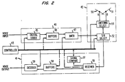
- FIG. 2 is a block diagram of a slightly different - radiotelephone set which, for example, can comprise a portable set for communication with the fixed, central PORT.
- the portable set comprises a transmitting section 40 a receiving section 41, an antenna section 42 and a controller 43.
- Transmitting section 40 comprises a digital coder 45, Buffers 46 and a transmitter 47 which function as described for coder 15, Buffers 16 and transmitter 17, respectively, of PORT transmitting section 10.
- Antenna section 42 comprises a first antenna 50 and a second antenna 51 which are separated to produce uncorrelated fading of the received signal and are oriented at different angles to provide different angular responses to the signal received from the PORT.
- a Transmit/Receive (T/R) selection switch 52 selects which of the transmitting section 40 or receiving section 41 is connected through antenna section 42 in response to control signals from controller 43.
- An antenna select switch 53 is responsive to control signals from controller 43 to connect the transmitting section 40 or the receiving section 41 to antenna 50 or antenna 51.
- the receiving section 41 comprises a single receiver 55, a signal comparison arrangement 57, Buffers 58 and a decoder 59 which function as described for receiver 25, signal comparison arrangement 27, Buffers 28 and decoder 29, respectively, of the PORT receiving section 11 of Figure 1.
- synchronism and transmission on a time division basis of special digital sequences between a Portable Set of Figure 2 and a PORT of Figure 1 make it possible for the Portable Set to determine which of its antennas 50 or 51 provides the best radio circuit for digitized voice or data transmission and reception.
- the synchronized sequence transmission makes this determination possible with only one receiver in the Portable Set.
- the performance of selection diversity and selection retransmission are achieved with a simpler Portable Set than is required for conventional multiple-receiver selection-diversity techniques.
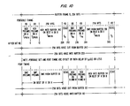
- Timing diagrams 9 and 10 Typical timing sequences for a particular timing example in accordance with the present invention are illustrated in the timing diagram of Figures 9 and 10. These diagrams are based on buffer frame lengths of 256 bits, preamble lengths of 6 bits and a guard or dead space between receive and transmit sequences of 4 bits.
- the digital coders 15 and 45 and decoders 29 and 59 in the example run at a rate of 32,000 bits/second. Other timing values and bit lengths can be used.
- each frame transmits an exemplary 256 bits of voice or data from the PORT and an exemplary 256 bits of voice or data from the Portable Set in the "RUN" mode when the system is in stable operation after a "STARTUP" mode.
- the PORT transmits from time 0 to time 6 an exemplary 6 preamble bits on the antenna 20 or 21 which was determined to receive the best signal from the Portable Set in the previous frame.
- the PORT transmits (t6-t12) the same 6 preamble bits over this same antenna 20 or 21 followed by the 256 bits of encoded voice or data.
- the Portable Set receives the first 6-bit preamble transmission.
- the receiver 55 of the Portable Set is connected to but one of the antennas 50 or 51 (e.g. 50), and the amplitude of the received signal is stored.
- the receiver 55 is connected to the other antenna (e.g., 51)
- the second 6-bit preamble from the PORT is received (t6-t12), and the amplitude of this signal (from antenna 51) is compared with the stored signal from antenna 52, to determine which antenna received the stronger signal.
- this determination is done using but a single receiver in the portable set.
- the antenna which received the stronger signal is used (t12-t268) to receive the 256-bit encoded voice or data signal from the PORT.
- the Portable Set After a 4-bit dead space (t268-272), the Portable Set transmits a 6-bit preamble (t272-t278) first via antenna 50 and then (t278-t284) via antenna 51 followed by 256 bits (t284-t540) of encoded voice or data on the antenna just previously found to receive the stronger signal.
- the PORT receives (t272-t278, t278-t284) the first and the second 6-bit preamble transmissions on each of antennas 20 and 21, and determines which antenna combination 50 to 20, 50 to 21, 51 to 20 or 51 to 21 received the stronger signal.
- the antenna 20 or 21 receiving the stronger signal is later used to transmit the 2 6-bit preamble signals and the 256-bit encoded voice or data signal to the Portable Set in the next frame (B; Figure 10).
- the 256-bit encoded voice or data signal from the Portable Set is then received (t284-t540), following reception of the preamble transmissions (t272-t284) from the Portable Set, via the antenna 20 or 21 having received the stronger preamble signal in the previous frame.
- the above-described sequence is then repeated.
- FIGS 3-5 and 6-8 are expanded block diagrams of the PORT and Portable Set arrangements, respectively, of Figures 1 and 2.
- Buffers 16 of PORT transmitter 16 is shown as comprising a first buffer 60 and a second buffer 61 each capable of storing 256 bits of encoded voice or data information.
- the inputs to buffers 60 and 61 are connected to separate output terminals of a Single-Pole, Double-Throw (SPDT) switching means 63 while the outputs of buffers 60 and 61 are connected to separate input terminals of a Single-Pole, Triple-Throw (SPTT) switching means 64.
- SPDT Single-Pole, Double-Throw
- SPTT Single-Pole, Triple-Throw
- a 6-bit preamble register 62 stores a 6- bit preamble and is connected at its output to a third input terminal of switching means 64.
- the reading of the preamble from preamble register 62 is timed by a bit clock pulse sequence on line "q" from controller 13 shown in Figure 4.
- Buffers 60 and 61 are selectively inputted at a predetermined clock rate from controller 13 via control signals on lines “b” and “d”, respectively, while buffers 60 and 61 are outputted at a predetermined clock rate from controller 13 via control lines “c” and “e”, respectively.
- the selection of the buffer 60 or 61 to receive the output signal from coder 15 via switching means 63, and the selection of either one of buffers 60-62 to be connected to transmitter 17 at any instant of time is determined by controller 13 via a control signal on line "f".
- Transmitter 17 of the PORT is shown as including a modulator 66 which modulates the output signal from Buffers 16 with a radio-frequency (RF) signal from RF source generator 67.
- the signal from modulator 66 is amplified in RF amplifier 68 and the amplified signal is transmitted to antenna section 12.
- the modulator 66 and RF amplifier 68 are turned on or off under the control of controller 13 via a control signal on line "h".
- Antenna section 12 of the PORT shows an enhanced view of each of the selective switches 22 and 23. More particularly, antenna selection switch 23 is shown as a SPDT switch which, under the control of controller 13 via a control signal on line "j", connects the output of transmitter 17 to a first or a second input to T/R selection switch 22 associated with antenna 20 or 21, respectively.
- T/ R selection switch 22 is shown as a pair of SPDT switches, each ascociated with a separate one of antennas 20 and 21. Each switch selectively connects the associated antenna to either one of transmitter 17 or a separate one of PORT receivers 25 and 26, shown in expanded view in Figure 5, in response to a control signal on line "i" from controller 13.
- each of receivers 25 and 26 has corresponding arrangements and only receiver 26 is described in detail.
- the input to receiver 26 is obtained from the associated antenna 21 via selection switch 22 of Figure 3 during the appropriate portion of the frame sequence shown in Figures 9 and 10.
- the RF input signal is received in an Amplifier-Mixing-Filtering device 70 which amplifies the received signal, downconverts it if necessary to, for example, IF frequencies and filters the signal to only pass the desired signal as is well-known in the art.
- the output signal from device 70 is concurrently transmitted to a Bit Synchronization device 71, a Bit Detector 72 and an Amplitude Detector 73.
- Bit Synchronization Device 71 uses the input signal from device 70 to provide bit synchronization pulses to Bit Detector 72, to Controller 13 via control line "1", and to a Preamble Detector 74.
- Bit Detector 72 functions to detect the received preamble and encoded voice or data signals
- Amplitude Detector 73 functions to detect the amplitude of the received signal.
- the output of Bit Detector 72 is transmitted to both the Preamble Detector 74 and Buffers 28 for temporary storage while the output of Amplitude Detector 73 is compared to a predetermined amplitude threshold in a Threshold Detector 75 and an indication of the strength of the received signal is transmitted to Signal Comparison arrangement 27.
- the output of Preamble Detector 74 is a pulse indicating the reception of a 6-bit preamble signal, which pulse is transmitted to Controller 13 via a control signal on line "n".
- receiver 25 comprises corresponding circuitry 70-75, with Preamble Detector 74 of receiver 25 providing an output control signal on line “m” to Controller 13 and an indication of the strength of the received signal on antenna 20 is sent to Signal Comparison arrangement 27.
- Bit Synchronization device 71 also provides bit synchronization pulses on line "k" to Controller 13.
- Signal Comparison arrangement 27 is shown as comprising 4 Sample and Hold (S/H) devices 80-83 with S/H devices 80 and 81 accepting the output from Amplitude Detector 73 of receiver 25 in response to control signals on lines "x" and “v”, respectively, from Controller 13 and SH devices 82 and 83 accepting the output from Amplitude Detector 73 of receiver 26 in response to control signals on lines "v” and "x", respectively, from Controller 13.
- the outputs from S/H devices 80-83 are transmitted to a comparison circuit 84 where the levels of S/H devices 80 to 83 are compared to determine which of the four received signals is the strongest. An indication of which is the strongest is transmitted to Controller 13 via a control signal on line "w".
- Buffers 28 is shown in Figure 5 as comprising a SPDT Receiver Selection switch 90, a pair of SPDT Buffer selection switches 91 and 92 and a first buffer 93 and a second buffer 94, each capable of storing 256 bits of encoded voice or data. More particularly, the two fixed terminals of switch 90 are connected to the outputs of separate ones of the Bit Detectors 72 of receivers 25 and 26. The movable arms of switches 90 and 91 are interconnected and buffers 93 and 94 are connected between separate ones of the fixed terminals of switches 91 and 92. The movable arm of switch 92 provides the output from Buffers 28 and is connected to the input of decoder 29.
- switch 90 is controlled by Controller 13 via a control signal on line “t” and the action of switches 91 and 92 is controlled from Controller 13 via a control signal on line “u”.
- Buffers 93 and 94 are selectively inputted at a predetermined clock rate from Controller 13 via control signals on lines “r” and “o” respectively, and are selectively outputted at a predetermined clock rate from Controller 13 via respective control signals on lines "q” and "p”.
- the decoder 29 is timed via decoder clock signals on line “s” from Controller 13, and the output from decoder 29 is transmitted to the intended end user.
- Controller 13 is shown in Figure 4 as comprising a master clock 100, a bit rate converter 101 including, for example, a frequency multiplier and divider of X8/17 for providing the basic clock rates of the system, a counter and digital logic count down 102 for providing various timed control pulses during a frame, a start-run mode control section 103 responsive to control signals from Preamble Detectors 74 of receivers 25 and 26 and timing signals from converter 101 and counter 102 for providing status control, a control section 104 responsive to timing pulses from counter 102, start-run mode control section 103 and Signal Comparison arrangement 27 to provide various control signals to the PORT, and a buffer clock section 105 responsive to control signals from counter 102 and bit synchronization switch 106 for providing the necessary control and timing signals to Buffers 16 and 28 to properly implement the timing diagram of Figure 5.
- a master clock 100 including, for example, a frequency multiplier and divider of X8/17 for providing the basic clock rates of the system
- a counter and digital logic count down 102 for
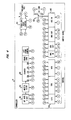
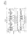
- FIGS 6-8 are enhanced block diagrams of the Portable Set of Figure 2.
- Buffers 46 of the Portable Set is shown as comprising a first and a second 256-bit buffer 200 and 201, a 6-bit preamble register 202, a SPDT switching means 203 and a SPTT switching means 204.
- Each of these elements 200-204 are connected and function as described for the corresponding elements 60-64 in PORT buffers 16 of Figure 3.
- Transmitter 47 is shown in Figure 6 as comprising a modulator 206, an RF Source 207 and an RF amplifier 208 which are connected and function as described for corresponding elements 66 ⁇ 68 in PORT transmitter 17 of Figure 3.
- the T/R selection switch 52 is shown as a SPDT switch with the output of transmitter 47 and the input to receiver 55 being connected to separate ones of the fixed terminals of switch 52.
- Antenna selection switch 53 is shown as a SPDT switch with the fixed terminals thereof being connected to separate ones of the antennas 50 and 51 and the movable arms of switches 52 and 53 being interconnected.
- receiver 55 is very similar to either one of receivers 25 or 26 or the PORT, shown in Figure 5, in that receiver 55 comprises an Amplifier-Mixer-Filter arrangement 220, a Bit Synchronization device 221, a Bit Detector 222, an Amplitude Detector 223 and a Threshold Detector 225 which are interconnected and function as described for corresponding elements 70-73 and 75 of receiver 26 in Figure 5.
- a Frame Synchronization device 224 replaces the Preamble Detector 74 of the PORT receiver, and functions to detect a received preamble and to generate a preamble received control signal on line "1" and a frame synchronization control signal on line "m" which is verified by a preamble detection section having received a valid preamble in the 6 bits after the frame synchronization control signal.
- the Signal Comparison arrangement 67 is shown in Figure 8 as comprising a first and a second Sample and Hold (S/H) device 230 and 231, and a comparison means 232.
- the inputs to the S/H devices 230 and 231 are from Amplitude Detector 223 in receiver 55 and the outputs therefrom are to comparison means 232.
- the inputting and outputting of information to and from S/H devices 230 and 231 is under the control of Controller 43, shown in Figure 7, via control signals on lines "u” and "t", respectively.
- the output from Comparison means 232 is a signal on line "v" to Controller 43 indicating which of devices 230 or 231 had the stronger signal for antenna selection for the reception of the 256-bit encoded voice or data signal from the PORT.
- Buffers 58 is shown in Figure 8 as including an input and an output buffer selection switch 240 and 241, respectively, and a first and a second buffer 242 and 243. Elements 240-243 are interconnected and function as described for the corresponding elements 91-94 of Buffers 28 in Figure 3.
- Controller 43 is shown in Figure 7 as comprising a Frame control section 250 for providing predetermined control signals for frame A and B, shown in Figures 9 and 10, at the start of each frame period, a bit rate converter 251, a counter and digital logic countdown section 252, a start-run mode control section 253, a control section 254 and a buffer clock section 255.
- Elements 251-255 function in the manner of corresponding elements 101-105 in Controller 13 in Figure 4.
- the transmit/receive, T/R, controller in Control Section 104 of Controller 13 connects the preamble register 62 to the modulator 66 via switching means 64 and a signal on line f, turns on the transmitter modulator 66 via line "h" and connects the antenna T/R switch 22 for transmit via line "i".
- the transmit antenna selection switch 23 is set via line "j" to either the vertically, V, or horizontally, H, polarized antenna 21 and 20 by the V/H controller logic of Control section 104.
- the selection of V or H is determined by which antenna 20 or 21 provided the best reception during the portable preamble-sequence transmission in the previous frame. The corresponding V/H selection sequence will be described for this frame later.
- the setting of the V/H antenna switch 23 for this frame using information derived in the previous frame is similar.
- the transmit out (xmt out) clock of Buffer Clock section 105 of Controller 13 drives the preamble register at rate R t via line "g" and the PORT transmitter 17 outputs 6 bits of preamble in time interval ⁇ 1PV/H.
- the Portable Set timing is controlled by a controllable clock synchronized to the PORT transmissions by a bit synchronizer 221 in the receiver 55.
- the bit clock on line “k” also drives a counter and logic 252 and the Buffer Clock section 255 of Controller 43.
- Frame synchronism is derived in Frame Synchronization device 224 that detects the preamble transmitted from the PORT and generates a frame sync pulse on line "m” by counting the bit clock.
- This frame sync pulse on line “m” is passed through the Start-Run Mode control section 253 of controller 43in the "RUN” mode and appears on line “w” to establish frame sync for the counter and controllers in controller 43.
- the counter and logic of Counter 252 provide control pulses on lines Z,-Z 6 at bit intervals following the frame sync pulse of 6, 12, 272, 278, 284 and 540 bits. These pulses are used to control transmit/receive, antenna selection, sample and hold and buffer sequences in sections 254 and 255 as described below.
- the bit clock and frame sync in the Portable Set are synchronized with the incoming bits and frames transmitted from the PORT.
- the Portable Set timing will be delayed from the PORT timing by the radio path delay which will be only about 1 ⁇ sec for a 1000 foot radio path. This delay will be accommodated in the 4 bit guard space mentioned earlier and described in more detail later.
- the digital coder 45 is connected to the input of transmit buffer 201 and the decoder 59 is connected to the output of receive buffer 243 by the T/R controller portion of section 254 via line "f" and by the frame controller 250 via line “n” respectively.
- This connection is initiated by the frame sync from Start-Run Mode Control section 253 on line "w”.
- the buffer clocks from section 255 of Controller 43 are also connected to clock the transmit buffer 201 and the receive buffer 243 at rate R c via lines "d” and "p” respectively.
- both the coder 45 and the decoder 59 are continuously clocked at rate R c via lines "a" and "s".
- the T/R control logic portion controls the antenna T/R selection switch 52 via line “i" to connect the receiver 55 to the A/B antenna selection switch 53.
- the A/B control logic of section 254 controls the A/B antenna selection switch 53 via line “j" to connect the receiver 55 to antenna 50.
- antennas 50 and 51 are spaced apart to produce uncorrelated multipath signal fading and are oriented perpendicular to each other to uncorrelate the signal fading resulting from random orientation of the Portable Set.
- the frame control 250 of Controller 43 connects the bit detector 222 into buffer 242 via switch 240 by a control signal on line "n".
- the sample-and-hold, S/H, control logic portion of section 254 sets a S/H circuit 231 for signal level acquisition via a control signal on line "t".
- the Portable Set then receives the 6-bit preamble transmitted from the PORT in time interval ⁇ 1PV/H ⁇ If the signal level received by the Portable Set is adequate as determined by Amplitude Detector 223 and Threshold Detector 225, the bit synchronization is updated in device 221, the preamble is decoded in Frame Synchronization device 224, a preamble received pulse is produced by Frame Synchronization device 224 on line "I" and the frame synchronisation for line "m” is verified. At the end of the 6-bit period, ⁇ 1PVH, the S/H device 231 is caused to hold the received signal level via line "t".
- the PORT control configuration remains unchanged.
- the 6-bit preamble transmission is repeated by the PORT in time interval i 2PVH .
- the A/B control logic portion of Section 254 of Controller 43 switches the A/B antenna selection switch 53 to antenna 51 via line "j".
- the S/H control logic portion of Section 254 sets S/H circuit 230 for signal level acquisition via line "u".
- the Portable Set then receives the 6-bit preamble transmitted from the PORT in time interval T2PV/H - If the signal level received by the Portable Set is adequate as determined by Amplitude Detector 223 and Threshold Detector 225, the bit synchronization in device 221 is updated, the preamble is decoded in Frame Synchronization device 224, a preamble received pulse is produced on line "I", and frame synchronization for line "m” is verified. At the end of T 2PV/H , a pulse on line "u" to S/H device 230 causes the received signal level to be held. It must be understood that in order to remain in the RUN mode, either the signal received on antenna 50 or on antenna 51 must be adequate. Otherwise, the Portable Set Start-Run Mode control section 253 of controller 43 switches the Portable Set back to "STARTUP" mode to be described later.
- the PORT configures to transmit digitized voice or data.
- the PORT transmitter and antenna configurations remain as in ⁇ 1PV/H and ⁇ 2PV/H .
- the T/R Control portion of section 104 of controller 13 in Figure 4 connects transmit buffer 60 to the modulator 66 via switch 64 by a control signal on line "f".
- the transmitter output clock portion of section 105 of controller 13 pulses at rate R t on line "c" to transmit the 256-bit contents of buffer 60 in time interval ⁇ MV/H,
- the Portable Set knows which antenna, 50 or 51, received the strongest signal and this information is present as an output from the level comparator 232 of signal comparison arrangement 57 on line "v".
- the comparator 232 output is processed in the A/B control logic of section 254 of controller 43 and the antenna switch 53 is switched via line "j" to the antenna, 50 or 51, that received the strongest signal during ⁇ 1PV/H and ⁇ 2PV/H .
- the bit detector 222 output was switched into buffer 242.
- the receiver input buffer clock of section 255 of controller 43 puts pulses on line "r" at a rate R, to cause the digitized voice or data transmitted by the PORT to be received into Portable-Set receive buffer 242.
- the PORT stops transmitting.
- the T/R controller portion of section 104 of controller 13 turns off the PORT transmitter 17 and switches the antenna T/R switch 22 to receive via lines "h" and "i", respectively.
- the input of receive buffer 93 is connected to the receiver output via switch 91 and a control signal on line "u".
- the 4-bit guard time i.e., dead time
- This guard time allows energy stored in system filters and in the multipath propagation medium to decay so interference will not be caused to reception in the opposite direction in the next time intervals.
- two S/H circuits 81 and 82 are set for signal level acquisition by the PORT S/H control logic portion of section 104 of controller 13 via line "v".
- the PORT is thus configured to receive on both antennas.
- the T/R controller in section 254 of controller 43 in the Portable Set turns on the transmitter 47 and connects the transmitter 47 to the antenna selection switch 52 via lines "h" and "i", respectively.
- the A/B controller portion of Section 254 connects the transmitter 47 to antenna 5.0 via switch 53 by a control signal on line "j".
- the T/R controller of section 254 connects the preamble register 202 output to the modulator 206 via switch 204 by a control signal on line "f".
- the transmitter output buffer clock in section 255 of controller 43 drives the preamble register 202 at rate R t via line "g" to transmit the 6-bit preamble on antenna 50 during time interval Ip A .
- the PORT receives the 6-bit preamble transmitted from the Portable Set. If the signal level received in one or the other PORT receivers 25 or 26 (or both) is adequate as determined by Threshold Detectors 75, the associated bit synchronization is updated in Bit Synchronization Device 71, the preamble is detected in Detector 74, and a preamble received pulse is produced on line "m" and/or "n". Bit synchronization is recovered in each PORT receiver 25 and 26 to adjust for PORT-to-Portable-to-PORT transmission delays between the master clock 100 and the receivers. The guard time allows the exact instant of frame timing to be less critical. Therefore, frame timing is controlled by the master clock 100.
- the PORT S/H controller portion of section 104 of controller 13 sets the two S/H circuits 81 and 82 to hold via line “v” and sets the other two S/H circuits 80 and 83 for signal acquisition via line "x".
- the portable antenna select switch 53 is set to antenna 51 by the A/B controller portion of section 254 of controller 43 via line "j".
- the transmit output buffer clock portion of section 255 of controller 43 continues to drive the preamble register 202 via line "g" to transmit the 6-bit preamble on antenna 51 during time interval Tp B .
- the PORT receives the 6-bit preamble transmitted from the Portable Set. If the signal level received in one or the other PORT receivers (or both) is adequate as determined by Threshold Detector 75 in each receiver 25 and 26, the associated bit synchronization in Bit Synchronization device 71 is updated, the preamble is detected in Preamble Detector 74, and a preamble received pulse is produced on line "m" and/or line "n".
- the PORT S/H controller portion of section 104 of controller 13 sets the two S/H circuits 80 and 83 to hold via line "x".
- the PORT comparator 84 knows on which antenna the strongest signal was received and this information is transmitted on line "w" to controller 13. This is the information used to determine on which antenna, 20 or 21, the PORT will transmit during time intervals, ⁇ 1PVH , ⁇ 2PV/H and - ⁇ MV/H in the next buffer frame, i.e., in the next frame B shown in Figure 10. It is the information similarly derived during time intervals T PA and ⁇ PB in previous frame B that was used to determine the PORT antenna for transmission during intervals T lPV/H , ⁇ 2 p V/H and ⁇ MV/H of this frame A discussed earlier.
- the Portable Set transmits on antenna 50 or 51, depending on which antenna, 50 or 51, the strongest signal was received from the PORT during earlier intervals, ⁇ 1PV/H and T 2PV/H , in this frame A.
- the appropriate antenna selection is made by logic in the A/B controller portion of section 254 in controller 43 and the antenna selection switch 53 is set via line "j".
- the T/R controller portion of section 254 of controller 43 connects portable-set transmit buffer 200 to the modulator 206 via switch 204 and a control signal on line "f".
- the 256 bits stored in buffer 200 are transmitted during interval ⁇ MA / B .
- ⁇ MA/B' buffer 200 is clocked at rate R t by the transmit-out portion of the buffer clock section 255 in Controller 43 via line "c".
- the PORT receives on the antenna, 20 or 21, which was used to transmit to the Portable Set in intervals ⁇ 1PV/H, T 2 p V/H and T MV/H earlier in this frame A and which was determined to be the best antenna (received the strongest signal) during T p A and ⁇ PB of the previous frame B.
- the appropriate PORT receiver, 25 or 26, output, V or H, to be connected to, for example, the receiver buffer 93 is selected by the V/H controller in section 104 of controller 13 via line "t" and switch 90 in Buffers 28, and the appropriate bit clock is selected via line " Ys " from control section 104 to operate switch 106 in controller 13.
- the 256 bits received by the PORT from the Portable Set are clocked into buffer 93 by the PORT receiver 25 or 26 input clock via line "r".
- the Portable Set T/R controller in section 254 of controller 43 turns off the transmitter 47 and switches the antenna to the receiver with switch 52 via lines "h" and "i", respectively.
- the time interval TMA/B is followed by another guard time indicated on the timing diagram with an interval length of 4 bits at rate R t .
- frame B At the PORT the next frame, frame B, shown in Figure 10, starts with a frame sync pulse from section 102 in controller 13 on line “Z 6 " that occurs at the end of the 4-bit guard time that follows ⁇ MA/B .
- frame sequencing pulses on line “Z 7 " from section 102 of controller 13 cause switching of the transmit and receive Buffers 16 and 28.
- the digital coder 15 output is switched via switch 63 into the transmit buffer 60 by the T/R controller in section 104 of controller 13 via line "f".
- the output of receive buffer 93 is switched via switch 92 to the decoder 29 input by the T/R controller in section 104 of controller 13 via line "u".
- the transmit buffer input clock and the receive buffer output clock are connected to clock transmit buffer 60 and received buffer 93 at rate R e via lines "b" and "q", respectively, from controller 13.
- the coder 15 and decoder 29 continue to be clocked at rate R e .
- Transmissions and receptions at the PORT during frame B are illustrated in the timing diagram of Figure 10. These transmissions and receptions follow the same sequences as described earlier for frame A of Figure 9 with the following modifications; 1) during time interval TMV/H , the PORT transmits from buffer 61 and 2) during time interval ⁇ MA/B' the PORT receives into buffer 94.
- frame B starts with a frame sync pulse passed from the output of Frame Synchronization device 224 on line "m" to line "w” through the Start-Run Mode controller 253 of controller 43.
- the input to transmit buffer 200 is connected to the digital coder 45 via switch 203 by the T/R controller portion of section 254 of controller 43 via line “f” and the receive buffer 242 is connected to the decoder 59 via switch 241 by the frame controller 250 via line "n".
- the transmit buffer input clock and the receive buffer output clock from section 255 of controller 43 are connected to clock the transmit buffer 200 and the receive buffer 242 at rate R e via lines "b" and "q", respectively.
- the coder 45 and decoder 59 continue to be clocked at rate R e .
- Transmission and reception sequences during frame B are illustrated in the timing diagram of Figure 10. These sequences follow the same sequences described earlier for frame A of Figure 9 with the following modifications: 1) during time interval ⁇ MV/H' the Portable Set receives into buffer 243 and 2) during time interval ⁇ MA/B' the Portable Set transmits from buffer 201.
- the requirement for this system to provide good selection diversity performance is as follows; the elapsed time between the acquisition of knowledge of the best antenna in time intervals ⁇ ⁇ A and TPB and the last time that the knowledge is used in time interval ⁇ MA/ ⁇ in the next frame must be small compared to the period of the multipath or orientation fading of the signals. For the system described, this elapsed time is about 12 milliseconds. For a 900 MHz radio system, the multipath fading period is about 100 milliseconds for motion of 5 ft./second. Thus, for this motion rate which is typical of walking, the 12 milliseconds is about 12 percent of the fading period which will provide good selection diversity performance. For faster motion rates, the buffer frame sequence can be appropriately shortened.
- Start-Run Mode controllers 103 and 253 in the PORT and the Portable, respectively revert to the respective STARTUP modes.
- the decoder 29 and 59 clock pulses on line "s" are inhibited to silence the respective receiver outputs.
- the PORT cycles through the transmit-receive sequence for a frame as described for the RUN mode.
- the PORT Start-Run Mode controller 103 causes the V/H antenna controller in section 104 of controller 13 via line "y4" to alternate the antenna selection switch 23 via line "j" between the antennas 20 and 21 in alternate buffer frames. Reception of a valid preamble by the preamble detector 74 in receivers 25 or 26 causes the Start-Run Mode controller 103 via lines "m” or 'n" to change to the RUN mode described earlier.
- the Portable Set Start-Run Mode controller 253 in controller 43 produces frame sync pulses on line "w" after every 12th bit at rate R t . Information for these extra sync pulses comes from the counter 252 via line "Z 2 ".
- These STARTUP Mode sync pulses cause the Portable Set to receive on antenna 50 for a 6-bit time interval ⁇ 1PV/H' then to receive on antenna 51 for a 6-bit time interval ⁇ 2PV/H' then to recycle to receive on antenna 50 for another ⁇ 1PV/H' etc.
- the Portable Set bit clock from bit synchronization device 221 via line "k” will synchronize with the PORT transmissions
- the frame synchronizer 224 will detect the PORT preamble and synchronize the Portable Set frame to the PORT frame
- the Portable Set START-Run Mode controller 253 in controller 43 Will switch to the RUN mode.
- antennas 50 and 51 can comprise a combination of loops and dipoles integrally mounted on a single antenna as shown in Figure 2 of the article "Polarization Diversity System for Mobile Radio" by W. C-Y. Lee et al in IEEE Transactions on Communication, Vol. COM-20, No. 5, October 1972 at page 913. Other modifications can be made using known components for the inventive system.
Landscapes
- Engineering & Computer Science (AREA)
- Computer Networks & Wireless Communication (AREA)
- Signal Processing (AREA)
- Mobile Radio Communication Systems (AREA)
- Radio Transmission System (AREA)
Claims (4)
Applications Claiming Priority (2)
| Application Number | Priority Date | Filing Date | Title |
|---|---|---|---|
| US06/488,397 US4513412A (en) | 1983-04-25 | 1983-04-25 | Time division adaptive retransmission technique for portable radio telephones |
| US488397 | 1995-06-07 |
Publications (2)
| Publication Number | Publication Date |
|---|---|
| EP0124319A1 EP0124319A1 (de) | 1984-11-07 |
| EP0124319B1 true EP0124319B1 (de) | 1987-09-30 |
Family
ID=23939571
Family Applications (1)
| Application Number | Title | Priority Date | Filing Date |
|---|---|---|---|
| EP84302627A Expired EP0124319B1 (de) | 1983-04-25 | 1984-04-17 | Funktelefone |
Country Status (5)
| Country | Link |
|---|---|
| US (1) | US4513412A (de) |
| EP (1) | EP0124319B1 (de) |
| JP (1) | JPH0648793B2 (de) |
| CA (1) | CA1207390A (de) |
| DE (1) | DE3466630D1 (de) |
Cited By (2)
| Publication number | Priority date | Publication date | Assignee | Title |
|---|---|---|---|---|
| US5657358A (en) | 1985-03-20 | 1997-08-12 | Interdigital Technology Corporation | Subscriber RF telephone system for providing multiple speech and/or data signals simultaneously over either a single or plurality of RF channels |
| US5852604A (en) | 1993-09-30 | 1998-12-22 | Interdigital Technology Corporation | Modularly clustered radiotelephone system |
Families Citing this family (120)
| Publication number | Priority date | Publication date | Assignee | Title |
|---|---|---|---|---|
| AU577742B2 (en) * | 1984-07-13 | 1988-09-29 | Motorola, Inc. | Cellular voice and data radiotelephone system |
| US4730310A (en) * | 1985-05-03 | 1988-03-08 | American Telephone And Telegraph Company | Terrestrial communications system |
| US4704734A (en) * | 1986-02-18 | 1987-11-03 | Motorola, Inc. | Method and apparatus for signal strength measurement and antenna selection in cellular radiotelephone systems |
| US4710944A (en) * | 1986-10-17 | 1987-12-01 | Rca Corporation | Dual transmit-receive space diversity communication system |
| US4747160A (en) * | 1987-03-13 | 1988-05-24 | Suite 12 Group | Low power multi-function cellular television system |
| CA1292584C (en) * | 1987-11-30 | 1991-11-26 | Henry Ludwig Kazecki | Antenna selection control circuit |
| US4977616A (en) * | 1987-11-30 | 1990-12-11 | Motorola, Inc. | Antenna selection control circuit |
| US5280631A (en) * | 1988-06-15 | 1994-01-18 | Matsushita Electric Works, Ltd. | Polarization diversity system suitable for radio communication in indoor space |
| JPH0744492B2 (ja) * | 1988-06-15 | 1995-05-15 | 松下電工株式会社 | 偏波ダイバーシチ無線通信方式 |
| NO175659C (no) * | 1988-07-06 | 1994-11-09 | Sumitomo Electric Industries | Kommunikasjonssystem med multippelmottagning og mottagerapparat for diversitetssignaler |
| US5095535A (en) * | 1988-07-28 | 1992-03-10 | Motorola, Inc. | High bit rate communication system for overcoming multipath |
| US5097484A (en) * | 1988-10-12 | 1992-03-17 | Sumitomo Electric Industries, Ltd. | Diversity transmission and reception method and equipment |
| JP2746658B2 (ja) * | 1988-10-12 | 1998-05-06 | 科学技術振興事業団 | アンテナ選択ダイバーシティー無線機 |
| US4953197A (en) * | 1988-12-08 | 1990-08-28 | International Mobile Machines Corporation | Combination spatial diversity system |
| JPH02200020A (ja) * | 1989-01-30 | 1990-08-08 | Nippon Telegr & Teleph Corp <Ntt> | アンテナ切替ダイバーシチ方式 |
| DE69024525T2 (de) * | 1989-05-02 | 1996-05-15 | Nippon Electric Co | TDMA-Raumdiversity-Empfänger |
| JPH0338932A (ja) * | 1989-07-06 | 1991-02-20 | Oki Electric Ind Co Ltd | スペースダイバーシチ方式 |
| SE464955B (sv) * | 1989-11-03 | 1991-07-01 | Ericsson Telefon Ab L M | Foerfarande att indela en ramstruktur i en mobilstation |
| US5001742A (en) * | 1990-01-29 | 1991-03-19 | At&T Bell Laboratories | Baseband signal processing unit and method of operating the same |
| JP2552928B2 (ja) * | 1990-01-31 | 1996-11-13 | 三菱電機株式会社 | アンテナ選択ダイバーシチ受信装置 |
| SE465991B (sv) * | 1990-04-10 | 1991-11-25 | Ericsson Telefon Ab L M | Foerfarande foer att i en mottagare vaelja den laempligaste av tvaa eller flera antenner |
| US5203024A (en) * | 1990-04-27 | 1993-04-13 | Nippon Telegraph & Telephone Corp. | Antenna selection diversity reception system |
| GB2254971B (en) * | 1991-03-07 | 1994-12-21 | Ericsson Telefon Ab L M | Mobile radio communications stations |
| JP3016919B2 (ja) * | 1991-08-28 | 2000-03-06 | 日本電気株式会社 | ダイバーシチ受信装置 |
| FI90703C (fi) * | 1992-02-14 | 1994-03-10 | Nokia Mobile Phones Ltd | Diversiteettiboosteri |
| US5479448A (en) * | 1992-03-31 | 1995-12-26 | At&T Corp. | Method and apparatus for providing antenna diversity |
| DE4213881A1 (de) * | 1992-04-28 | 1993-11-04 | Bosch Gmbh Robert | System zur bidirektionalen datenuebertragung zwischen einer bake und einem fahrzeug |
| DE4213879A1 (de) * | 1992-04-28 | 1993-11-04 | Bosch Gmbh Robert | Kommunikationssystem zur datenuebertragung von einem bewegten fahrzeug auf eine ortsfeste bake |
| DE4213882A1 (de) * | 1992-04-28 | 1993-11-04 | Bosch Gmbh Robert | Vorrichtung eines fahrzeugs zur datenuebertragung auf eine ortsfeste bake und damit gebildetes kommunikationssystem |
| EP0573856B1 (de) * | 1992-06-12 | 1998-10-14 | Siemens Aktiengesellschaft | Funkgerät |
| US5918184A (en) * | 1992-09-21 | 1999-06-29 | Lucent Technologies Inc. | Method and apparatus for detecting a supervisory audio tone |
| US5289464A (en) * | 1992-09-21 | 1994-02-22 | At&T Bell Laboratories | Frequency-multiplexed cellular telephone cell site base station and method of operating the same |
| US5446922A (en) * | 1992-12-21 | 1995-08-29 | Motorola, Inc. | Method and apparatus for switched diversity reception of a radio signal |
| EP0622910B1 (de) * | 1993-04-29 | 2003-06-25 | Ericsson Inc. | Zeitdiversityübertragungssystem zum Herabsetzung der Nachbarkanalstörung in Mobiltelefonsystemen |
| US5507035A (en) * | 1993-04-30 | 1996-04-09 | International Business Machines Corporation | Diversity transmission strategy in mobile/indoor cellula radio communications |
| GB9309353D0 (en) * | 1993-05-06 | 1993-06-16 | Ncr Int Inc | Wireless communication system having antenna diversity |
| US5781592A (en) * | 1993-09-28 | 1998-07-14 | Kabushiki Kaisha Toshiba | Selective diversity system |
| US5581707A (en) * | 1994-07-27 | 1996-12-03 | Psc, Inc. | System for wireless collection of data from a plurality of remote data collection units such as portable bar code readers |
| DE4430987C1 (de) * | 1994-08-31 | 1995-11-23 | Siemens Ag | Antennenschalter für drahtlose Antennendiversity-Telekommunikationsgeräte mit zwei Antennen |
| US5628052A (en) * | 1994-09-12 | 1997-05-06 | Lucent Technologies Inc. | Wireless communication system using distributed switched antennas |
| JP3243130B2 (ja) * | 1994-10-31 | 2002-01-07 | 松下電器産業株式会社 | アダプティブアンテナ付き受信装置 |
| US5617102A (en) * | 1994-11-18 | 1997-04-01 | At&T Global Information Solutions Company | Communications transceiver using an adaptive directional antenna |
| GB2298338B (en) * | 1995-02-15 | 1999-09-29 | Motorola Ltd | A method for reverse channel sounding in a communications system |
| US5748676A (en) * | 1995-05-01 | 1998-05-05 | Norand Corporation | Network utilizing modified preambles that support antenna diversity |
| ATE255300T1 (de) * | 1995-05-18 | 2003-12-15 | Aura Communications Inc | Magnetische kommunikationssystem mit geringer reichweite |
| US5912925A (en) | 1995-05-18 | 1999-06-15 | Aura Communications, Inc. | Diversity circuit for magnetic communication system |
| US5982764A (en) * | 1995-05-18 | 1999-11-09 | Aura Communications, Inc. | Time-multiplexed short-range magnetic communications |
| US5768268A (en) * | 1995-07-19 | 1998-06-16 | Watkins Johnson Company | Wideband base station architecture for digital cellular communications system |
| GB2307375A (en) * | 1995-11-20 | 1997-05-21 | British Broadcasting Corp | Mobile Radio Communication System with Diversity Reception |
| JPH09284364A (ja) * | 1996-04-15 | 1997-10-31 | Sony Corp | 電話装置及び音声符号化復号化方法 |
| US5692019A (en) * | 1996-06-17 | 1997-11-25 | Motorola, Inc. | Communication device having antenna switch diversity, and method therefor |
| US6243565B1 (en) * | 1996-06-18 | 2001-06-05 | Telefonaktiebolaget Lm Ericsson (Publ) | Method and apparatus for transmitting communication signals using frequency and polarization diversity |
| US5995492A (en) * | 1996-06-28 | 1999-11-30 | Ctp Systems, Ltd. | Method and apparatus for using duality to remotely communicate |
| ES2149412T3 (es) * | 1996-09-20 | 2000-11-01 | Siemens Ag | Sistema de diversidad de polarizacion para comunicaciones moviles con configuracion adaptable de las caracteristicas de radiacion. |
| EP0833461B1 (de) * | 1996-09-26 | 2000-07-26 | Siemens Aktiengesellschaft | Empfangseinrichtung mit Polarisationsdiversity für rahmenorientierte Mobilkommunikationssysteme |
| US6243372B1 (en) * | 1996-11-14 | 2001-06-05 | Omnipoint Corporation | Methods and apparatus for synchronization in a wireless network |
| US5903826A (en) * | 1996-12-06 | 1999-05-11 | Northern Telecom Limited | Extremely high frequency multipoint fixed-access wireless communication system |
| US5930248A (en) * | 1997-03-04 | 1999-07-27 | Telefonaktiebolaget Lm Ericsson | Radio communication system selectively using multicast with variable offset time |
| JPH10283088A (ja) * | 1997-04-02 | 1998-10-23 | Oki Electric Ind Co Ltd | シリアル通信回路 |
| EP1060619B1 (de) * | 1998-03-05 | 2002-07-03 | Formula One Administration Limited | Datenübertragungssystem |
| US6490261B1 (en) | 1999-10-28 | 2002-12-03 | Ericsson Inc. | Overlapping slot transmission using phased arrays |
| EP1169750A4 (de) * | 2000-01-21 | 2004-12-08 | Motorola Inc | Sytem und verfahren zur funkkommunikation mit polarisationsdiversität |
| DE10014352A1 (de) * | 2000-03-24 | 2001-10-04 | Elan Schaltelemente Gmbh & Co | Anordnung und Verfahren zur Übertragung sicherheitsrelevanter Daten über eine Funkstrecke |
| DE60222779T2 (de) * | 2001-02-14 | 2008-07-03 | Ntt Docomo Inc. | Kommunikationsregelungsverfahren und Vorrichtung in einem Mobilfunksystem |
| US7142811B2 (en) * | 2001-03-16 | 2006-11-28 | Aura Communications Technology, Inc. | Wireless communication over a transducer device |
| US7532901B1 (en) | 2001-03-16 | 2009-05-12 | Radeum, Inc. | Methods and apparatus to detect location and orientation in an inductive system |
| US6961545B2 (en) * | 2001-04-09 | 2005-11-01 | Atheros Communications, Inc. | Method and system for providing antenna diversity |
| GB2376843B (en) * | 2001-06-18 | 2005-01-12 | Ubinetics Ltd | A transmitter station and a radiotelephone system including a transmitter station |
| US7103382B2 (en) * | 2001-07-10 | 2006-09-05 | Kyocera Wireless Corp. | System and method for receiving and transmitting information in a multipath environment |
| JP2005537759A (ja) * | 2002-09-06 | 2005-12-08 | ノキア コーポレイション | アンテナ選択方法 |
| US7006824B1 (en) | 2002-09-10 | 2006-02-28 | Marvell International Ltd. | Frame/packet-based calibration for wireless transceivers |
| JP3577307B2 (ja) * | 2002-11-26 | 2004-10-13 | 沖電気工業株式会社 | 受信装置 |
| US7627054B2 (en) * | 2004-04-26 | 2009-12-01 | Vicente Diaz Fuente | Device and method for improving the signal to noise ratio by means of complementary sequences |
| US8233555B2 (en) | 2004-05-17 | 2012-07-31 | Qualcomm Incorporated | Time varying delay diversity of OFDM |
| ES2255390B1 (es) * | 2004-05-28 | 2008-02-01 | Vicente Diaz Fuente | Dispositivo y metodo de estimacion optima de la distorsion del medio de transmision mediante la emision secuencial de pares de secuencias complementarias en cuadratura. |
| US7965252B2 (en) * | 2004-08-18 | 2011-06-21 | Ruckus Wireless, Inc. | Dual polarization antenna array with increased wireless coverage |
| US7880683B2 (en) * | 2004-08-18 | 2011-02-01 | Ruckus Wireless, Inc. | Antennas with polarization diversity |
| US7933628B2 (en) * | 2004-08-18 | 2011-04-26 | Ruckus Wireless, Inc. | Transmission and reception parameter control |
| US7292198B2 (en) * | 2004-08-18 | 2007-11-06 | Ruckus Wireless, Inc. | System and method for an omnidirectional planar antenna apparatus with selectable elements |
| US8031129B2 (en) * | 2004-08-18 | 2011-10-04 | Ruckus Wireless, Inc. | Dual band dual polarization antenna array |
| US7193562B2 (en) | 2004-11-22 | 2007-03-20 | Ruckus Wireless, Inc. | Circuit board having a peripheral antenna apparatus with selectable antenna elements |
| US7899497B2 (en) * | 2004-08-18 | 2011-03-01 | Ruckus Wireless, Inc. | System and method for transmission parameter control for an antenna apparatus with selectable elements |
| US7696946B2 (en) * | 2004-08-18 | 2010-04-13 | Ruckus Wireless, Inc. | Reducing stray capacitance in antenna element switching |
| US7652632B2 (en) * | 2004-08-18 | 2010-01-26 | Ruckus Wireless, Inc. | Multiband omnidirectional planar antenna apparatus with selectable elements |
| US7627296B2 (en) * | 2004-10-18 | 2009-12-01 | Research In Motion Limited | Method of controlling a plurality of internal antennas in a mobile communication device |
| US7505447B2 (en) * | 2004-11-05 | 2009-03-17 | Ruckus Wireless, Inc. | Systems and methods for improved data throughput in communications networks |
| US8638708B2 (en) | 2004-11-05 | 2014-01-28 | Ruckus Wireless, Inc. | MAC based mapping in IP based communications |
| TWI391018B (zh) | 2004-11-05 | 2013-03-21 | Ruckus Wireless Inc | 藉由確認抑制之增強資訊量 |
| US8619662B2 (en) | 2004-11-05 | 2013-12-31 | Ruckus Wireless, Inc. | Unicast to multicast conversion |
| US7358912B1 (en) | 2005-06-24 | 2008-04-15 | Ruckus Wireless, Inc. | Coverage antenna apparatus with selectable horizontal and vertical polarization elements |
| US8792414B2 (en) * | 2005-07-26 | 2014-07-29 | Ruckus Wireless, Inc. | Coverage enhancement using dynamic antennas |
| US7893882B2 (en) | 2007-01-08 | 2011-02-22 | Ruckus Wireless, Inc. | Pattern shaping of RF emission patterns |
| US7646343B2 (en) * | 2005-06-24 | 2010-01-12 | Ruckus Wireless, Inc. | Multiple-input multiple-output wireless antennas |
| WO2007064822A2 (en) | 2005-12-01 | 2007-06-07 | Ruckus Wireless, Inc. | On-demand services by wireless base station virtualization |
| WO2007127120A2 (en) * | 2006-04-24 | 2007-11-08 | Ruckus Wireless, Inc. | Dynamic authentication in secured wireless networks |
| US9769655B2 (en) | 2006-04-24 | 2017-09-19 | Ruckus Wireless, Inc. | Sharing security keys with headless devices |
| US9071583B2 (en) * | 2006-04-24 | 2015-06-30 | Ruckus Wireless, Inc. | Provisioned configuration for automatic wireless connection |
| US7639106B2 (en) * | 2006-04-28 | 2009-12-29 | Ruckus Wireless, Inc. | PIN diode network for multiband RF coupling |
| US20070293178A1 (en) * | 2006-05-23 | 2007-12-20 | Darin Milton | Antenna Control |
| US8670725B2 (en) * | 2006-08-18 | 2014-03-11 | Ruckus Wireless, Inc. | Closed-loop automatic channel selection |
| US8547899B2 (en) | 2007-07-28 | 2013-10-01 | Ruckus Wireless, Inc. | Wireless network throughput enhancement through channel aware scheduling |
| RU2354048C1 (ru) * | 2007-11-28 | 2009-04-27 | Открытое акционерное общество "Концерн "Созвездие" | Способ и система связи с быстрым вхождением в синхронизм сверхширокополосными сигналами |
| US8355343B2 (en) | 2008-01-11 | 2013-01-15 | Ruckus Wireless, Inc. | Determining associations in a mesh network |
| US8217843B2 (en) * | 2009-03-13 | 2012-07-10 | Ruckus Wireless, Inc. | Adjustment of radiation patterns utilizing a position sensor |
| US8698675B2 (en) * | 2009-05-12 | 2014-04-15 | Ruckus Wireless, Inc. | Mountable antenna elements for dual band antenna |
| US20100302991A1 (en) * | 2009-06-02 | 2010-12-02 | Qualcomm Incorporated | System and process for transmit diversity in satellite phones |
| US9979626B2 (en) | 2009-11-16 | 2018-05-22 | Ruckus Wireless, Inc. | Establishing a mesh network with wired and wireless links |
| US9999087B2 (en) * | 2009-11-16 | 2018-06-12 | Ruckus Wireless, Inc. | Determining role assignment in a hybrid mesh network |
| US20120052827A1 (en) * | 2010-08-26 | 2012-03-01 | Qualcomm Incorporated | Decision directed antenna diversity in radio frequency receivers |
| US9407012B2 (en) | 2010-09-21 | 2016-08-02 | Ruckus Wireless, Inc. | Antenna with dual polarization and mountable antenna elements |
| EP2705429B1 (de) | 2011-05-01 | 2016-07-06 | Ruckus Wireless, Inc. | Fernzurücksetzung eines kabelzugangspunktes |
| US8756668B2 (en) | 2012-02-09 | 2014-06-17 | Ruckus Wireless, Inc. | Dynamic PSK for hotspots |
| US10186750B2 (en) | 2012-02-14 | 2019-01-22 | Arris Enterprises Llc | Radio frequency antenna array with spacing element |
| US9634403B2 (en) | 2012-02-14 | 2017-04-25 | Ruckus Wireless, Inc. | Radio frequency emission pattern shaping |
| US9092610B2 (en) | 2012-04-04 | 2015-07-28 | Ruckus Wireless, Inc. | Key assignment for a brand |
| US9570799B2 (en) | 2012-09-07 | 2017-02-14 | Ruckus Wireless, Inc. | Multiband monopole antenna apparatus with ground plane aperture |
| US8891415B2 (en) | 2012-10-04 | 2014-11-18 | Harris Corporation | Wireless communications system including single channel retransmission and related methods |
| JP6032543B2 (ja) * | 2012-10-19 | 2016-11-30 | パナソニックIpマネジメント株式会社 | アンテナ切り替え受信システム及びそれに対応する送信システム |
| JP6032544B2 (ja) * | 2012-10-19 | 2016-11-30 | パナソニックIpマネジメント株式会社 | アンテナ切り替え受信システム及びそれに対応する送信システム |
| EP2974045A4 (de) | 2013-03-15 | 2016-11-09 | Ruckus Wireless Inc | Niedrigbandreflektor für eine gerichtete doppelbandantenne |
Citations (1)
| Publication number | Priority date | Publication date | Assignee | Title |
|---|---|---|---|---|
| US4041397A (en) * | 1976-04-28 | 1977-08-09 | The United States Of America As Represented By The Secretary Of The Navy | Satellite up link diversity switch |
Family Cites Families (13)
| Publication number | Priority date | Publication date | Assignee | Title |
|---|---|---|---|---|
| GB368954A (en) * | 1931-02-23 | 1932-03-17 | Kolster Radio Corp | System for reducing fading effects in radio communication |
| US2694141A (en) * | 1951-12-22 | 1954-11-09 | Bell Telephone Labor Inc | Radiant energy signaling system |
| US3696421A (en) * | 1969-06-06 | 1972-10-03 | Bell Telephone Labor Inc | Space diversity phased array retransmission system using time division |
| US3631494A (en) * | 1969-08-08 | 1971-12-28 | Bell Telephone Labor Inc | Retransmission system |
| US3835392A (en) * | 1970-12-03 | 1974-09-10 | Siemens Ag | System for two or more combined communication channels regulated in accordance with linear relationships |
| US3693088A (en) * | 1970-12-29 | 1972-09-19 | Bell Telephone Labor Inc | Diversity system for mobile radio using fade rate switching |
| CA1065020A (en) * | 1974-06-27 | 1979-10-23 | William L. Hatton | High reliability diversity communications system |
| JPS5147313A (de) * | 1974-10-21 | 1976-04-22 | Nippon Telegraph & Telephone | |
| DE2534888C2 (de) * | 1975-08-05 | 1983-12-08 | Licentia Patent-Verwaltungs-Gmbh, 6000 Frankfurt | Antennendiversityverfahren und Anordnung zur Durchführung des Verfahrens |
| US4128809A (en) * | 1976-08-31 | 1978-12-05 | Nippon Electric Co., Ltd. | Time diversity receiver for processing repeatedly received signal bits in consideration of a maximum-level and/or a favorably received signal bit |
| JPS54121016A (en) * | 1978-03-13 | 1979-09-19 | Nec Corp | Communication control unit |
| US4317218A (en) * | 1980-03-26 | 1982-02-23 | General Electric Company | Arrangement for remote control of repeater stations |
| US4383332A (en) * | 1980-11-21 | 1983-05-10 | Bell Telephone Laboratories, Incorporated | High capacity digital mobile radio system |
-
1983
- 1983-04-25 US US06/488,397 patent/US4513412A/en not_active Expired - Lifetime
-
1984
- 1984-03-28 CA CA000450727A patent/CA1207390A/en not_active Expired
- 1984-04-17 DE DE8484302627T patent/DE3466630D1/de not_active Expired
- 1984-04-17 EP EP84302627A patent/EP0124319B1/de not_active Expired
- 1984-04-25 JP JP59082100A patent/JPH0648793B2/ja not_active Expired - Lifetime
Patent Citations (1)
| Publication number | Priority date | Publication date | Assignee | Title |
|---|---|---|---|---|
| US4041397A (en) * | 1976-04-28 | 1977-08-09 | The United States Of America As Represented By The Secretary Of The Navy | Satellite up link diversity switch |
Cited By (13)
| Publication number | Priority date | Publication date | Assignee | Title |
|---|---|---|---|---|
| US6771667B2 (en) | 1985-03-20 | 2004-08-03 | Interdigital Technology Corporation | Subscriber RF telephone system for providing multiple speech and/or data signals simultaneously over either a single or a plurality of RF channels |
| US5687194A (en) | 1985-03-20 | 1997-11-11 | Interdigital Technology Corporation | Subscriber RF telephone system for providing multiple speech and/or data signals simultaneously over either a single or a plurality of RF channels |
| US5734678A (en) | 1985-03-20 | 1998-03-31 | Interdigital Technology Corporation | Subscriber RF telephone system for providing multiple speech and/or data signals simultaneously over either a single or a plurality of RF channels |
| US6014374A (en) | 1985-03-20 | 2000-01-11 | Interdigital Technology Corporation | Subscriber RF telephone system for providing multiple speech and/or data signals simultaneously over either a single or a plurality of RF channels |
| US6282180B1 (en) | 1985-03-20 | 2001-08-28 | Interdigital Technology Corporation | Subscriber RF telephone system for providing multiple speech and/or data signals simultaneously over either a single or a plurality of RF channels |
| US6393002B1 (en) | 1985-03-20 | 2002-05-21 | Interdigital Technology Corporation | Subscriber RF telephone system for providing multiple speech and/or data signals simultaneously over either a single or a plurality of RF channels |
| US5657358A (en) | 1985-03-20 | 1997-08-12 | Interdigital Technology Corporation | Subscriber RF telephone system for providing multiple speech and/or data signals simultaneously over either a single or plurality of RF channels |
| US6842440B2 (en) | 1985-03-20 | 2005-01-11 | Interdigital Technology Corporation | Subscriber RF telephone system for providing multiple speech and/or data signals simultaneously over either a single or a plurality of RF channels |
| US6954470B2 (en) | 1985-03-20 | 2005-10-11 | Interdigital Technology Corporation | Subscriber RF telephone system for providing multiple speech and/or data signals simultaneously over either a single or a plurality of RF channels |
| US5852604A (en) | 1993-09-30 | 1998-12-22 | Interdigital Technology Corporation | Modularly clustered radiotelephone system |
| US6208630B1 (en) | 1993-09-30 | 2001-03-27 | Interdigital Technology Corporation | Modulary clustered radiotelephone system |
| US6496488B1 (en) | 1993-09-30 | 2002-12-17 | Interdigital Technology Corporation | Modularly clustered radiotelephone system |
| US7245596B2 (en) | 1993-09-30 | 2007-07-17 | Interdigital Technology Corporation | Modularly clustered radiotelephone system |
Also Published As
| Publication number | Publication date |
|---|---|
| JPS59207753A (ja) | 1984-11-24 |
| EP0124319A1 (de) | 1984-11-07 |
| US4513412A (en) | 1985-04-23 |
| CA1207390A (en) | 1986-07-08 |
| JPH0648793B2 (ja) | 1994-06-22 |
| DE3466630D1 (en) | 1987-11-05 |
Similar Documents
| Publication | Publication Date | Title |
|---|---|---|
| US4513412A (en) | Time division adaptive retransmission technique for portable radio telephones | |
| CA1083224A (en) | Apparatus for indicating synchronization and out-of- synchronization conditions | |
| CA1083225A (en) | Apparatus for establishing communication between a first radio transmitter and receiver and a second radio transmitter and receiver | |
| US6671496B1 (en) | Transmitter and receiver communication apparatus with transmitter switch and receiver switch | |
| EP0158327B1 (de) | Kommunikationssystem mit Raum-Diversity für Mehrrichtungsverbindungen im Zeitmultiplex | |
| EP0808033B1 (de) | Datenempfänger mit Antennen-Diversity | |
| EP0350007B1 (de) | Kommunikationssystem mit Antennen diversity | |
| US5097484A (en) | Diversity transmission and reception method and equipment | |
| AU635132B2 (en) | A method of transmitting different commands relating to the choice of transmitter antenna in a time multiplex radio communication system | |
| US6317424B1 (en) | Antenna diversity radio receiving arrangement for telecommunications systems using block-oriented transmission of radio messages | |
| US5020051A (en) | Duplex communications method and system | |
| WO1999034535A1 (en) | An improved antenna diversity switching system for tdma-based telephones | |
| CA1083223A (en) | Apparatus for indicating synchronization of a radio receiver with a radio transmitter | |
| JPH04151915A (ja) | 移動通信用一周波数交互通信方式 | |
| US6912248B1 (en) | Equalizer circuit and equalizing | |
| US6073009A (en) | Radio signal controller radio communication device, radio communication system and methods of controlling a radio | |
| JP2001517912A (ja) | 多重タイムスロット移動局に対する最適化された隣接チャネル探索およびタイムスロット割り当て | |
| CA1181183A (en) | Time compression multiplex digital transmission system | |
| JP2798985B2 (ja) | ディジタル無線受信装置 | |
| JPH02200020A (ja) | アンテナ切替ダイバーシチ方式 | |
| JPH06303220A (ja) | ダイバーシチ受信装置 | |
| JP2782816B2 (ja) | 移動通信システム | |
| JPH0560286B2 (de) | ||
| EP0686337A1 (de) | Verbesserungen bezüglich des weiterreichens in einen digitalen schnurlosen telefonsystem | |
| SU1246389A2 (ru) | Устройство дл выбора радиосигналов с разнесенных антенн |
Legal Events
| Date | Code | Title | Description |
|---|---|---|---|
| PUAI | Public reference made under article 153(3) epc to a published international application that has entered the european phase |
Free format text: ORIGINAL CODE: 0009012 |
|
| AK | Designated contracting states |
Designated state(s): DE FR GB IT NL SE |
|
| 17P | Request for examination filed |
Effective date: 19850411 |
|
| 17Q | First examination report despatched |
Effective date: 19860307 |
|
| GRAA | (expected) grant |
Free format text: ORIGINAL CODE: 0009210 |
|
| AK | Designated contracting states |
Kind code of ref document: B1 Designated state(s): DE FR GB IT NL SE |
|
| ITF | It: translation for a ep patent filed | ||
| REF | Corresponds to: |
Ref document number: 3466630 Country of ref document: DE Date of ref document: 19871105 |
|
| ET | Fr: translation filed | ||
| PLBE | No opposition filed within time limit |
Free format text: ORIGINAL CODE: 0009261 |
|
| STAA | Information on the status of an ep patent application or granted ep patent |
Free format text: STATUS: NO OPPOSITION FILED WITHIN TIME LIMIT |
|
| 26N | No opposition filed | ||
| ITTA | It: last paid annual fee | ||
| EAL | Se: european patent in force in sweden |
Ref document number: 84302627.9 |
|
| REG | Reference to a national code |
Ref country code: GB Ref legal event code: IF02 |
|
| PGFP | Annual fee paid to national office [announced via postgrant information from national office to epo] |
Ref country code: FR Payment date: 20020327 Year of fee payment: 19 |
|
| PGFP | Annual fee paid to national office [announced via postgrant information from national office to epo] |
Ref country code: GB Payment date: 20020402 Year of fee payment: 19 |
|
| PGFP | Annual fee paid to national office [announced via postgrant information from national office to epo] |
Ref country code: NL Payment date: 20020403 Year of fee payment: 19 |
|
| PGFP | Annual fee paid to national office [announced via postgrant information from national office to epo] |
Ref country code: SE Payment date: 20020416 Year of fee payment: 19 |
|
| PGFP | Annual fee paid to national office [announced via postgrant information from national office to epo] |
Ref country code: DE Payment date: 20020628 Year of fee payment: 19 |
|
| PG25 | Lapsed in a contracting state [announced via postgrant information from national office to epo] |
Ref country code: GB Free format text: LAPSE BECAUSE OF NON-PAYMENT OF DUE FEES Effective date: 20030417 |
|
| PG25 | Lapsed in a contracting state [announced via postgrant information from national office to epo] |
Ref country code: SE Free format text: LAPSE BECAUSE OF NON-PAYMENT OF DUE FEES Effective date: 20030418 |
|
| PG25 | Lapsed in a contracting state [announced via postgrant information from national office to epo] |
Ref country code: NL Free format text: LAPSE BECAUSE OF NON-PAYMENT OF DUE FEES Effective date: 20031101 Ref country code: DE Free format text: LAPSE BECAUSE OF NON-PAYMENT OF DUE FEES Effective date: 20031101 |
|
| NLV4 | Nl: lapsed or anulled due to non-payment of the annual fee |
Effective date: 20031101 |
|
| EUG | Se: european patent has lapsed | ||
| GBPC | Gb: european patent ceased through non-payment of renewal fee |
Effective date: 20030417 |
|
| PG25 | Lapsed in a contracting state [announced via postgrant information from national office to epo] |
Ref country code: FR Free format text: LAPSE BECAUSE OF NON-PAYMENT OF DUE FEES Effective date: 20031231 |
|
| REG | Reference to a national code |
Ref country code: FR Ref legal event code: ST |