EP0123638A2 - Système de vidange du réfrigérant liquide d'un sous refroidisseur dans un système frigorifique à compression de vapeur - Google Patents
Système de vidange du réfrigérant liquide d'un sous refroidisseur dans un système frigorifique à compression de vapeur Download PDFInfo
- Publication number
- EP0123638A2 EP0123638A2 EP84630053A EP84630053A EP0123638A2 EP 0123638 A2 EP0123638 A2 EP 0123638A2 EP 84630053 A EP84630053 A EP 84630053A EP 84630053 A EP84630053 A EP 84630053A EP 0123638 A2 EP0123638 A2 EP 0123638A2
- Authority
- EP
- European Patent Office
- Prior art keywords
- subcooler
- refrigeration system
- drain
- refrigerant
- vapor compression
- Prior art date
- Legal status (The legal status is an assumption and is not a legal conclusion. Google has not performed a legal analysis and makes no representation as to the accuracy of the status listed.)
- Granted
Links
Images
Classifications
-
- F—MECHANICAL ENGINEERING; LIGHTING; HEATING; WEAPONS; BLASTING
- F25—REFRIGERATION OR COOLING; COMBINED HEATING AND REFRIGERATION SYSTEMS; HEAT PUMP SYSTEMS; MANUFACTURE OR STORAGE OF ICE; LIQUEFACTION SOLIDIFICATION OF GASES
- F25B—REFRIGERATION MACHINES, PLANTS OR SYSTEMS; COMBINED HEATING AND REFRIGERATION SYSTEMS; HEAT PUMP SYSTEMS
- F25B1/00—Compression machines, plants or systems with non-reversible cycle
- F25B1/04—Compression machines, plants or systems with non-reversible cycle with compressor of rotary type
- F25B1/053—Compression machines, plants or systems with non-reversible cycle with compressor of rotary type of turbine type
-
- F—MECHANICAL ENGINEERING; LIGHTING; HEATING; WEAPONS; BLASTING
- F25—REFRIGERATION OR COOLING; COMBINED HEATING AND REFRIGERATION SYSTEMS; HEAT PUMP SYSTEMS; MANUFACTURE OR STORAGE OF ICE; LIQUEFACTION SOLIDIFICATION OF GASES
- F25B—REFRIGERATION MACHINES, PLANTS OR SYSTEMS; COMBINED HEATING AND REFRIGERATION SYSTEMS; HEAT PUMP SYSTEMS
- F25B39/00—Evaporators; Condensers
-
- F—MECHANICAL ENGINEERING; LIGHTING; HEATING; WEAPONS; BLASTING
- F25—REFRIGERATION OR COOLING; COMBINED HEATING AND REFRIGERATION SYSTEMS; HEAT PUMP SYSTEMS; MANUFACTURE OR STORAGE OF ICE; LIQUEFACTION SOLIDIFICATION OF GASES
- F25B—REFRIGERATION MACHINES, PLANTS OR SYSTEMS; COMBINED HEATING AND REFRIGERATION SYSTEMS; HEAT PUMP SYSTEMS
- F25B41/00—Fluid-circulation arrangements
- F25B41/20—Disposition of valves, e.g. of on-off valves or flow control valves
Definitions
- the present invention relates to vapor compression refrigeration systems having tube in shell heat exchangers and, more particularly, relates to vapor compression refrigeration systems having tube in shell subcoolers used in low temperature cooling applications such as in a brine chilling application.
- Water freeze-up is a problem because usually the brine in the evaporator is chilled in the evaporator to a temperature below the freezing temperature of water and equalization of refrigerant temperature and pressure in the refrigeration system at shutdown of the refrigeration system results in refrigerant temperatures in the subcooler dropping to a temperature below the freezing temperature of water for a period of time sufficient to freeze the water in the tubes of the subcooler. If too much water freezes in the tubes of the subcooler, then the subcooler tubes may break or other such undesirable results may occur.
- the danger of freezing water in the tubes of the subcooler may be reduced by taking measures such as maintaining water flow through the tubes of the subcooler after shutdown of the refrigeration system for a period of time sufficient to allow the refrigeration system to equalize at a temperature above the freezing temperature of water.
- this type of operation is inefficient because a water pump must be maintained in operation for a period of time after each shutdown of the refrigeration system.
- subcooler freeze-up may still occur. Therefore, this is not a particularly satisfactory way of overcoming the subcooler freeze-up problem.
- a vapor compression refrigeration system with a tube in shell subcooler having a drain system for quickly draining liquid refrigerant from the shell side of the subcooler at shutdown of the refrigeration system.
- the liquid refrigerant is drained fast enough to prevent refrigerant temperatures in the subcooler from dropping to temperatures below the freezing temperature of water for a period of time sufficient to freeze undesirable amounts of water in the tubes of the subcooler.
- a subcooler liquid refrigerant drain system may comprise a drain line connected between the subcooler and the evaporator of the refrigeration system, a valve located in the drain line, a sensor for sensing shutdown of the refrigeration system, and a control, responsive to the sensor, for opening the valve in the drain line to drain liquid refrigerant from the subcooler to the evaporator when the sensor senses shutdown of the refrigeration system.
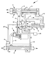
- the Figure shows a schematic illustration of a vapor compression refrigeration system 1 having a tube in shell subcooler 3 with a drain system 4 for draining liquid refrigerant from the subcooler 3 at shutdown of the refrigeration system 1 according to the principles of the present invention.
- the refrigeration system 1 is designed for use in low temperature cooling applications such as a brine chilling application.
- the vapor compression refrigeration 1 includes a condenser 2, a flash economizer 5, an evaporator 6, a two- stage centrifugal compressor 7, and an electronic control center 8 for controlling the operation of the refrigeration system 1.
- the subcooler 3 and the condenser 2 are housed in one shell 10 having a partition plate 9 separating the subcooler section 3 from the condenser section 2.
- the condenser 2 and subcooler 3 may be housed in separate shells.
- a flash economizer 5 is included as part of the refrigeration system 1. However, if desired, the flash economizer 5 may be omitted from the refrigeration system 1 without altering the basic structure and operation of the present invention.
- a subcooler liquid refrigerant outlet line 11 connecting the subcooler 3 and the flash economizer 5.
- Flow of liquid refrigerant through the subcooler liquid refrigerant outlet line 11 to the flash economizer 5 is controlled by a high pressure side float valve 12 which senses refrigerant liquid level in the subcooler 3 through a subcooler liquid level sensor line 13.
- a flash economizer liquid refrigerant outlet line 14 connects the flash economizer 5 to the evaporator 6.
- Flow of liquid refrigerant through the flash economizer liquid refrigerant outlet line 14 to the evaporator 6 is controlled by a low pressure side float valve 15.
- a compressor refrigerant vapor inlet line 16 connects the evaporator 6 to the inlet of the centrifugal compressor 7.
- a compressor refrigerant vapor outlet line 17 connects the outlet of the centrifugal compressor 7 to the condenser 2.
- An economizer flash gas outlet line 18 connects the flash economizer 5 to the second stage of the centrifugal compressor 7.
- the drain system 4 comprises a drain line 20, a pressure operated control valve 21 located in the drain line 20, and a three-way solenoid valve 22 for opening and closing the pressure operated control valve 21.
- the drain line 20 is connected between the subcooler liquid refrigerant outlet line 11 and the flash economizer liquid refrigerant outlet line 14.
- the three-way solenoid valve 22 has an outlet pressure line 23 connected to the control valve 21, a first inlet pressure line 24 for connection to a relatively low pressure source, and a second inlet pressure line 25 for connection to a relatively high pressure source.
- the relatively low pressure source is atmosphere'surrounding the vapor compression refrigeration system 1 and the relatively high pressure source is a compressed air supply 26.
- electrical leads 27 electrically connect the three-way solenoid valve 22 to the electronic control center 8 for the vapor compression refrigeration system 1.
- the drain line 20 is sized, positioned and configured relative to the refrigeration system 1 to drain substantially all of the liquid refrigerant from the subcooler 3 in a predetermined amount of time when the control valve 21 in the drain 20 is opened at shutdown of the refrigeration system 1.
- individual refrigeration systems will vary in their size and configuration.
- the drain line 20 must be especially sized, positioned and configured for the particular refrigeration system according to conventional hydraulic engineering principles depending on factors such as the difference in height between the subcooler 3 and evaporator 6, the refrigerant pressure difference between the subcooler 3 and evaporator 6 at shutdown of the refrigeration system 1, the size of the subcooler 3, and the amount of liquid refrigerant normally present in the subcooler 3 at shutdown of the refrigeration system 1.
- the predetermined drain time for the drain system 4 is selected to be less than the amount of time in which an undesirable amount of water may freeze in the tubes 32 of the subcooler 3 after shutdown of the refrigeration system 1.
- This freezing time may be determined in a variety of ways which will be readily apparent to one of ordinary skill in the art to which the present invention pertains. For example, one way of determining this freezing time-is to calculate the amount of time after shutdown of the refrigeration system 1 necessary to freeze enough water in one of the tubes 32 of the subcooler 3 to exceed a designed stress limitation for the tube. This calculation may be carried out by considering the ice which builds up in the tube and the tube itself as two tubes with an interference fit caused by the differential thermal expansion between the ice and the tube.
- the time required to freeze ice in the tube to the designed stress limit may be calculated at different equalization refrigerant temperatures for the subcooler 3 by considering the thermal resistance of the ice, the thermal resistance of the material from which the tube is made, and the thermal resistance of the film of refrigerant on the outside surface of the tube.
- the heat flux equation for an infinite long tube combined with the latent heat of solidification for water gives the freezing time.
- a worst case freezing time is calculated by assuming a worst case equalization temperature, by assuming that there is stagnant water in the subcooler tubes 32 at shutdown of the refrigeration system 1, by neglecting the thermal expansion of the material from which the tubes are made, and by neglecting the sensible cooling of water in the subcooler tubes 32. Based on this calculated worst case freezing time and based on engineering experience and judgement regarding a particular refrigeration system 1, one may select a safe freezing time for the refrigeration system 1 and design the drain system 4 to have a drain time less than this selected safe freezing time.
- the pressure operated control valve 21 in the drain line 20 is an air pressure operated valve such as a butterfly type valve.
- the control valve 21 is open when atmospheric air pressure is supplied to the control valve 21 through the outlet pressure line 23 of the solenoid valve 22 and is closed when higher pressure air from the compressed air supply 26 is supplied to the control valve 21 through the outlet pressure line 23 of the solenoid valve 22.
- the three-way solenoid valve 22 may be any one of a variety of such valves for connecting an outlet line to either one of two inlet lines while effectively sealing off the other inlet line from the outlet line.
- the three-way solenoid valve 22 is electrically connected by the electrical leads 27 to the electronic control center 8 so that the outlet pressure line 23 is connected to the first inlet pressure line 24 when no electrical power is supplied to the solenoid valve 22 from the electronic control center 8 and so that the outlet pressure line 23 is connected to the second inlet pressure line 25 when electrical power is supplied to the solenoid valve 22 from the electronic control center 8.
- the control valve 21 in the drain line 20 is closed when electrical power is supplied to the solenoid valve 22 because then the relatively high pressure air source is connected to the control valve 21 and the control valve 21 is open when no electrical power is supplied to the solenoid valve 22 because then the relatively low pressure air source is connected to the control valve 21.
- the electronic control center 8 includes electrical components for monitoring the operation of the refrigeration system 1.
- the electronic control center 8 may include electrical components for sensing electrical power flow to the motor for the centrifugal compressor 7.
- the refrigeration system 1 When electrical power flow is sensed, the refrigeration system 1 is operating and the electronic control center 8 supplies electrical power through the electrical leads 27 to the solenoid valve 22 thereby causing the control valve 21 in the drain line 20 to close.
- the refrigeration system When no electrical power flow is sensed, the refrigeration system is not operating and the electronic control center 8 supplies no electrical power through the electrical leads 27 to the solenoid valve 22 thereby causing the control valve 21 in the drain line 20 to open and drain liquid refrigerant from the subcooler 3.
- drain line 20 inlet may be connected directly to the subcooler 3 and/or the drain line 20 outlet may be connected directly to the evaporator 6.
- no special drain line 20 need be provided and, instead, at shutdown of the refrigeration system 1 the high pressure side float valve 12 may be opened to drain the liquid refrigerant from the subcooler 3 through the subcooler liquid refrigeration outlet line 11 into the flash economizer 5.
- a total electronic valving and control system may be used in place of the pressure operated control valve 21 and the three-way solenoid valve 22 shown in the Figure.
- a control system may be used which monitors the refrigerant pressure differential between the condenser 2 and the evaporator 6. The control valve 21 in the drain line 20 is opened when the monitored pressure differential falls below a preselected level indicating that the refrigeration system 1 is not operating.
- liquid refrigerant is evaporated in the evaporator 6 to chill a low temperature cooling medium such as brine flowing through tubes 30 in the evaporator 6.
- the chilled medium from the evaporator 6 is provided to heat exchanger means (not shown) for providing cooling capacity in an industrial process or for another such purpose.
- heat exchanger means not shown
- this heat exchange medium is chilled to a temperature below the freezing temperature of water.
- brine may be chilled to a temperature of 0° to 5° Fahrenheit.
- the refrigerant vapor from the evaporator 6 flows through the compressor refrigerant vapor inlet line 16 into the two- stage centrifugal compressor 7 which compresses the refrigerant vapor and supplies this compressed refrigerant vapor through the compressor refrigerant vapor outlet line 17 to the condenser 2.
- Relatively cool water flows through tubes 31 in the condenser 2 to cool the refrigerant vapor and condense the vapor to a liquid.
- the condensed liquid refrigerant from the condenser 2 is supplied to the subcooler 3 wherein the liquid refrigerant is further cooled by relatively cooler water flowing through tubes 32 in the subcooler 3.
- water flowing through the tubes 32 in the subcooler 3 is maintained at a lower temperature than water flowing through the tubes 31 in the condenser 2 by routing cooling water first through the tubes 32 in the subcooler 3 and then through the tubes 31 in the condenser 2.
- a separate water flow circuit may be provided for the condenser 2 and for the subcooler 3 or other kinds of water flow circuiting may be used.
- the subcooler 3 is the type of subcooler (also known as a thermal economizer) which lowers the temperature of the liquid refrigerant flowing through the shell side of the subcooler 3 by sensible heat transfer to water flowing through the tubes 32 in the subcooler 3.
- a thermal economizer which lowers the temperature of the liquid refrigerant flowing through the shell side of the subcooler 3 by sensible heat transfer to water flowing through the tubes 32 in the subcooler 3.
- This desired level of liquid refrigerant in the subcooler 3 is maintained by operation of the high pressure side float valve 12 which controls the amount of flow of liquid refrigerant from the subcooler 3 through the subcooler liquid refrigerant outlet line 11 to the flash economizer 5.
- the pressure operated control valve 21 in the drain line 20 is closed to prevent refrigerant from flowing through the drain line 20.
- the control valve 21 is closed because the electronic control center 8 senses operation of the refrigeration system 1 and in response thereto supplies electrical power to the three-way solenoid valve 22 which connects the outlet pressure line 23 to the inlet pressure line 25.
- the relatively high pressure air source is connected to the control valve 21 causing the control valve 21 to close during normal operation of the refrigeration system 1.
- the subcooled refrigerant liquid from the subcooler 3 flows through the subcooler liquid refrigerant outlet line 11 to the flash economizer 5.
- a portion of this subcooled liquid refrigerant is flashed in the flash economizer 5 to further cool the remaining liquid portion of the refrigerant in the - flash economizer 5.
- the flashed refrigerant from the flash economizer 5 is supplied through the economizer flash gas outlet line 18 to the second stage of the compressor 7 wherein the refrigerant gas is recompressed and supplied back to the condenser 2.
- the relatively cold liquid portion of the refrigerant is supplied from the flash economizer 5 to the evaporator 6 through the flash economizer liquid refrigerant outlet line 14.
- the flow of this relatively cold liquid refrigerant through the flash economizer liquid refrigerant outlet line 14 to the evaporator 6 is controlled by operation of the low pressure side float valve 15.
- the centrifugal compressor 7 will cease operation and equalization of refrigerant pressure and temperature will occur in the refrigeration system 1. During this equalization period, a portion of the liquid refrigerant in the subcooler 3 will evaporate thereby greatly cooling the remaining portion of the liquid refrigerant in the subcooler 3. This will occur at shutdown because of exposure of the relatively high pressure and temperature refrigerant in the condenser 2 and the subcooler 3 to the relatively low pressure and temperature refrigerant on the low pressure side of the refrigeration system 1.
- the liquid refrigerant temperature in the subcooler 3 may equalize to a temperature below the freezing temperature of water. As discussed previously, if the liquid refrigerant temperature in the subcooler 3 remains too long at this equalization refrigerant - temperature below the freezing temperature of water then there is a danger of freezing an undesirable amount of water in the tubes 32 of the subcooler 3.
- the electronic control center 8 monitors the operation of the refrigeration system 1 and when the electronic control center 8 senses shutdown of the vapor compression refrigeration system 1 electrical power flow is discontinued to the three-way solenoid valve 22 of the drain system 4. This causes the three-way solenoid valve 22 to switch the air pressure connection of the outlet pressure line 23 from the inlet pressure line 25 which is connected to the relatively high pressure air source to the input pressure line 24 which is connected to the relatively low pressure air source.
- control valve 21 This causes the control valve 21 to open the drain line 20 thereby substantially draining all of the liquid refrigerant from the subcooler 3 in a predetermined amount of time which is less than the freezing time for the subcooler 3 thereby preventing any subcooler 3 freeze-up problems. Also, it should be noted that, with this type of control system for the control valve 21, if there is a total electrical power failure for the refrigeration system 1, then no electrical power will flow to the solenoid valve 22 and the subcooler 3 will be drained by the drain system 4 to prevent freeze-up problems in this situation.
Applications Claiming Priority (2)
| Application Number | Priority Date | Filing Date | Title |
|---|---|---|---|
| US06/485,976 US4475354A (en) | 1983-04-18 | 1983-04-18 | System for draining liquid refrigerant from a subcooler in a vapor compression refrigeration system |
| US485976 | 1983-04-18 |
Publications (3)
| Publication Number | Publication Date |
|---|---|
| EP0123638A2 true EP0123638A2 (fr) | 1984-10-31 |
| EP0123638A3 EP0123638A3 (en) | 1986-02-19 |
| EP0123638B1 EP0123638B1 (fr) | 1987-12-23 |
Family
ID=23930131
Family Applications (1)
| Application Number | Title | Priority Date | Filing Date |
|---|---|---|---|
| EP84630053A Expired EP0123638B1 (fr) | 1983-04-18 | 1984-04-03 | Système de vidange du réfrigérant liquide d'un sous refroidisseur dans un système frigorifique à compression de vapeur |
Country Status (4)
| Country | Link |
|---|---|
| US (1) | US4475354A (fr) |
| EP (1) | EP0123638B1 (fr) |
| JP (1) | JPS59200170A (fr) |
| DE (1) | DE3468274D1 (fr) |
Cited By (1)
| Publication number | Priority date | Publication date | Assignee | Title |
|---|---|---|---|---|
| EP2674698A1 (fr) * | 2012-06-14 | 2013-12-18 | Cadena Systems AG | Installation de pompes à chaleur |
Families Citing this family (8)
| Publication number | Priority date | Publication date | Assignee | Title |
|---|---|---|---|---|
| US4832068A (en) * | 1987-12-21 | 1989-05-23 | American Standard Inc. | Liquid/gas bypass |
| KR100376786B1 (ko) * | 2000-07-29 | 2003-03-19 | 만도공조 주식회사 | 터보 냉동기의 냉매량 제어장치 |
| US7299649B2 (en) * | 2003-12-09 | 2007-11-27 | Emerson Climate Technologies, Inc. | Vapor injection system |
| US7275385B2 (en) * | 2005-08-22 | 2007-10-02 | Emerson Climate Technologies, Inc. | Compressor with vapor injection system |
| US8037710B2 (en) * | 2005-08-22 | 2011-10-18 | Emerson Climate Technologies, Inc. | Compressor with vapor injection system |
| US8196425B2 (en) * | 2007-11-15 | 2012-06-12 | Imi Cornelius Inc. | Auxiliary sub-cooler for refrigerated dispenser |
| US8011196B2 (en) * | 2007-12-20 | 2011-09-06 | Trane International Inc. | Refrigerant control of a heat-recovery chiller |
| WO2014106252A1 (fr) | 2012-12-31 | 2014-07-03 | Trane International Inc. | Ensemble et méthode d'injection d'économiseur |
Citations (7)
| Publication number | Priority date | Publication date | Assignee | Title |
|---|---|---|---|---|
| US3161029A (en) * | 1962-10-04 | 1964-12-15 | Carrier Corp | Refrigeration systems operable at low condenser pressures |
| US3371500A (en) * | 1966-05-13 | 1968-03-05 | Trane Co | Refrigeration system starting |
| GB1197295A (en) * | 1966-09-02 | 1970-07-01 | Carrier Corp | Refrigerant Flow Control |
| US3589140A (en) * | 1970-01-05 | 1971-06-29 | Carrier Corp | Refrigerant feed control for centrifugal refrigeration machines |
| US3744264A (en) * | 1972-03-28 | 1973-07-10 | Trane Co | Refrigeration apparatus and method of operating for powered and non-powered cooling modes |
| GB2003263A (en) * | 1977-08-29 | 1979-03-07 | Carrier Corp | A compression, condensation evaporation refrigeration system |
| US4220011A (en) * | 1978-12-22 | 1980-09-02 | The Trane Company | Air cooled centrifugal refrigeration system with water heat recovery |
Family Cites Families (2)
| Publication number | Priority date | Publication date | Assignee | Title |
|---|---|---|---|---|
| US2401827A (en) * | 1943-09-06 | 1946-06-11 | Westinghouse Electric Corp | Refrigerating apparatus |
| US3744273A (en) * | 1972-03-27 | 1973-07-10 | Trane Co | Refrigeration apparatus and method of operating for powered and nonpowered cooling modes |
-
1983
- 1983-04-18 US US06/485,976 patent/US4475354A/en not_active Expired - Lifetime
-
1984
- 1984-04-03 EP EP84630053A patent/EP0123638B1/fr not_active Expired
- 1984-04-03 DE DE8484630053T patent/DE3468274D1/de not_active Expired
- 1984-04-10 JP JP59071682A patent/JPS59200170A/ja active Granted
Patent Citations (7)
| Publication number | Priority date | Publication date | Assignee | Title |
|---|---|---|---|---|
| US3161029A (en) * | 1962-10-04 | 1964-12-15 | Carrier Corp | Refrigeration systems operable at low condenser pressures |
| US3371500A (en) * | 1966-05-13 | 1968-03-05 | Trane Co | Refrigeration system starting |
| GB1197295A (en) * | 1966-09-02 | 1970-07-01 | Carrier Corp | Refrigerant Flow Control |
| US3589140A (en) * | 1970-01-05 | 1971-06-29 | Carrier Corp | Refrigerant feed control for centrifugal refrigeration machines |
| US3744264A (en) * | 1972-03-28 | 1973-07-10 | Trane Co | Refrigeration apparatus and method of operating for powered and non-powered cooling modes |
| GB2003263A (en) * | 1977-08-29 | 1979-03-07 | Carrier Corp | A compression, condensation evaporation refrigeration system |
| US4220011A (en) * | 1978-12-22 | 1980-09-02 | The Trane Company | Air cooled centrifugal refrigeration system with water heat recovery |
Cited By (1)
| Publication number | Priority date | Publication date | Assignee | Title |
|---|---|---|---|---|
| EP2674698A1 (fr) * | 2012-06-14 | 2013-12-18 | Cadena Systems AG | Installation de pompes à chaleur |
Also Published As
| Publication number | Publication date |
|---|---|
| EP0123638B1 (fr) | 1987-12-23 |
| DE3468274D1 (en) | 1988-02-04 |
| US4475354A (en) | 1984-10-09 |
| EP0123638A3 (en) | 1986-02-19 |
| JPH0348429B2 (fr) | 1991-07-24 |
| JPS59200170A (ja) | 1984-11-13 |
Similar Documents
| Publication | Publication Date | Title |
|---|---|---|
| US4197716A (en) | Refrigeration system with auxiliary heat exchanger for supplying heat during defrost cycle and for subcooling the refrigerant during a refrigeration cycle | |
| KR960010634B1 (ko) | 축열식 공기 조화장치 | |
| US4932221A (en) | Air-cooled cooling apparatus | |
| US7152426B1 (en) | Thermal control systems for process tools requiring operation over wide temperature ranges | |
| US4338794A (en) | High efficiency ice-making system | |
| JP3637786B2 (ja) | ブライン冷却装置 | |
| US4475354A (en) | System for draining liquid refrigerant from a subcooler in a vapor compression refrigeration system | |
| JPH0321813B2 (fr) | ||
| KR200377788Y1 (ko) | 음용수 냉각장치 | |
| US6993918B1 (en) | Thermal control systems for process tools requiring operation over wide temperature ranges | |
| EP3163220B1 (fr) | Système frigorifique de type à pompe à chaleur | |
| JP2516405B2 (ja) | 冷凍サイクルにおけるガス洩れ検出構造 | |
| JP2001004173A (ja) | 氷蓄熱式空気調和装置及び運転方法 | |
| US2895307A (en) | Refrigerating system including a hot gas defrosting circuit | |
| JPH07294073A (ja) | 冷凍装置 | |
| JP2789852B2 (ja) | 製氷装置 | |
| JP3467407B2 (ja) | 冷凍装置 | |
| EP3978828B1 (fr) | Dispositif à cycle frigorifique | |
| JPH03271643A (ja) | 氷蓄熱空調システムの運転方法 | |
| JP3492912B2 (ja) | 冷凍装置 | |
| JPH09280668A (ja) | 複合型冷媒回路設備 | |
| JPH06280563A (ja) | エンジンの冷却水温度制御方法及び装置 | |
| RU2150640C1 (ru) | Холодильная установка | |
| JPS5826513B2 (ja) | 冷却装置の異常状態検知装置 | |
| SU1657897A1 (ru) | Холодильна установка |
Legal Events
| Date | Code | Title | Description |
|---|---|---|---|
| PUAI | Public reference made under article 153(3) epc to a published international application that has entered the european phase |
Free format text: ORIGINAL CODE: 0009012 |
|
| AK | Designated contracting states |
Designated state(s): CH DE FR GB IT LI SE |
|
| PUAL | Search report despatched |
Free format text: ORIGINAL CODE: 0009013 |
|
| AK | Designated contracting states |
Designated state(s): CH DE FR GB IT LI SE |
|
| 17P | Request for examination filed |
Effective date: 19860411 |
|
| 17Q | First examination report despatched |
Effective date: 19860829 |
|
| GRAA | (expected) grant |
Free format text: ORIGINAL CODE: 0009210 |
|
| AK | Designated contracting states |
Kind code of ref document: B1 Designated state(s): CH DE FR GB IT LI SE |
|
| ET | Fr: translation filed | ||
| REF | Corresponds to: |
Ref document number: 3468274 Country of ref document: DE Date of ref document: 19880204 |
|
| ITF | It: translation for a ep patent filed |
Owner name: UFFICIO BREVETTI RICCARDI & C. |
|
| PLBE | No opposition filed within time limit |
Free format text: ORIGINAL CODE: 0009261 |
|
| STAA | Information on the status of an ep patent application or granted ep patent |
Free format text: STATUS: NO OPPOSITION FILED WITHIN TIME LIMIT |
|
| 26N | No opposition filed | ||
| ITTA | It: last paid annual fee | ||
| EAL | Se: european patent in force in sweden |
Ref document number: 84630053.1 |
|
| PGFP | Annual fee paid to national office [announced via postgrant information from national office to epo] |
Ref country code: FR Payment date: 19950309 Year of fee payment: 12 |
|
| PGFP | Annual fee paid to national office [announced via postgrant information from national office to epo] |
Ref country code: GB Payment date: 19950315 Year of fee payment: 12 |
|
| PGFP | Annual fee paid to national office [announced via postgrant information from national office to epo] |
Ref country code: SE Payment date: 19950320 Year of fee payment: 12 |
|
| PGFP | Annual fee paid to national office [announced via postgrant information from national office to epo] |
Ref country code: DE Payment date: 19950322 Year of fee payment: 12 Ref country code: CH Payment date: 19950322 Year of fee payment: 12 |
|
| PG25 | Lapsed in a contracting state [announced via postgrant information from national office to epo] |
Ref country code: GB Effective date: 19960403 |
|
| PG25 | Lapsed in a contracting state [announced via postgrant information from national office to epo] |
Ref country code: SE Effective date: 19960404 |
|
| PG25 | Lapsed in a contracting state [announced via postgrant information from national office to epo] |
Ref country code: LI Effective date: 19960430 Ref country code: CH Effective date: 19960430 |
|
| GBPC | Gb: european patent ceased through non-payment of renewal fee |
Effective date: 19960403 |
|
| REG | Reference to a national code |
Ref country code: CH Ref legal event code: PL |
|
| PG25 | Lapsed in a contracting state [announced via postgrant information from national office to epo] |
Ref country code: FR Effective date: 19961227 |
|
| PG25 | Lapsed in a contracting state [announced via postgrant information from national office to epo] |
Ref country code: DE Effective date: 19970101 |
|
| EUG | Se: european patent has lapsed |
Ref document number: 84630053.1 |
|
| REG | Reference to a national code |
Ref country code: FR Ref legal event code: ST |