EP0123083A2 - Steuerungssystem und Steuerungsverfahren für ein Kraftfahrzeug - Google Patents
Steuerungssystem und Steuerungsverfahren für ein Kraftfahrzeug Download PDFInfo
- Publication number
- EP0123083A2 EP0123083A2 EP84102527A EP84102527A EP0123083A2 EP 0123083 A2 EP0123083 A2 EP 0123083A2 EP 84102527 A EP84102527 A EP 84102527A EP 84102527 A EP84102527 A EP 84102527A EP 0123083 A2 EP0123083 A2 EP 0123083A2
- Authority
- EP
- European Patent Office
- Prior art keywords
- throttle
- indicative signal
- reduction ratio
- opening degree
- signal
- Prior art date
- Legal status (The legal status is an assumption and is not a legal conclusion. Google has not performed a legal analysis and makes no representation as to the accuracy of the status listed.)
- Granted
Links
- 238000000034 method Methods 0.000 title claims description 11
- 230000009467 reduction Effects 0.000 claims abstract description 77
- 230000005540 biological transmission Effects 0.000 claims description 20
- 230000004044 response Effects 0.000 claims description 12
- 230000007246 mechanism Effects 0.000 claims description 7
- 239000000446 fuel Substances 0.000 abstract description 12
- 238000011217 control strategy Methods 0.000 abstract description 2
- 230000008859 change Effects 0.000 description 22
- 230000008569 process Effects 0.000 description 4
- 230000009471 action Effects 0.000 description 3
- 238000010586 diagram Methods 0.000 description 2
- 239000012530 fluid Substances 0.000 description 2
- 125000006850 spacer group Chemical group 0.000 description 2
- VYZAMTAEIAYCRO-UHFFFAOYSA-N Chromium Chemical compound [Cr] VYZAMTAEIAYCRO-UHFFFAOYSA-N 0.000 description 1
- 230000002159 abnormal effect Effects 0.000 description 1
- 238000006243 chemical reaction Methods 0.000 description 1
- 229910052804 chromium Inorganic materials 0.000 description 1
- 239000011651 chromium Substances 0.000 description 1
- 230000003111 delayed effect Effects 0.000 description 1
- 230000000994 depressogenic effect Effects 0.000 description 1
- 230000000694 effects Effects 0.000 description 1
- 238000001704 evaporation Methods 0.000 description 1
- 239000011521 glass Substances 0.000 description 1
- 239000000696 magnetic material Substances 0.000 description 1
- 229910052751 metal Inorganic materials 0.000 description 1
- 239000002184 metal Substances 0.000 description 1
- 238000012986 modification Methods 0.000 description 1
- 230000004048 modification Effects 0.000 description 1
- VMXUWOKSQNHOCA-UKTHLTGXSA-N ranitidine Chemical compound [O-][N+](=O)\C=C(/NC)NCCSCC1=CC=C(CN(C)C)O1 VMXUWOKSQNHOCA-UKTHLTGXSA-N 0.000 description 1
Images


Classifications
-
- B—PERFORMING OPERATIONS; TRANSPORTING
- B60—VEHICLES IN GENERAL
- B60W—CONJOINT CONTROL OF VEHICLE SUB-UNITS OF DIFFERENT TYPE OR DIFFERENT FUNCTION; CONTROL SYSTEMS SPECIALLY ADAPTED FOR HYBRID VEHICLES; ROAD VEHICLE DRIVE CONTROL SYSTEMS FOR PURPOSES NOT RELATED TO THE CONTROL OF A PARTICULAR SUB-UNIT
- B60W10/00—Conjoint control of vehicle sub-units of different type or different function
- B60W10/04—Conjoint control of vehicle sub-units of different type or different function including control of propulsion units
- B60W10/06—Conjoint control of vehicle sub-units of different type or different function including control of propulsion units including control of combustion engines
-
- B—PERFORMING OPERATIONS; TRANSPORTING
- B60—VEHICLES IN GENERAL
- B60W—CONJOINT CONTROL OF VEHICLE SUB-UNITS OF DIFFERENT TYPE OR DIFFERENT FUNCTION; CONTROL SYSTEMS SPECIALLY ADAPTED FOR HYBRID VEHICLES; ROAD VEHICLE DRIVE CONTROL SYSTEMS FOR PURPOSES NOT RELATED TO THE CONTROL OF A PARTICULAR SUB-UNIT
- B60W10/00—Conjoint control of vehicle sub-units of different type or different function
- B60W10/04—Conjoint control of vehicle sub-units of different type or different function including control of propulsion units
-
- B—PERFORMING OPERATIONS; TRANSPORTING
- B60—VEHICLES IN GENERAL
- B60W—CONJOINT CONTROL OF VEHICLE SUB-UNITS OF DIFFERENT TYPE OR DIFFERENT FUNCTION; CONTROL SYSTEMS SPECIALLY ADAPTED FOR HYBRID VEHICLES; ROAD VEHICLE DRIVE CONTROL SYSTEMS FOR PURPOSES NOT RELATED TO THE CONTROL OF A PARTICULAR SUB-UNIT
- B60W10/00—Conjoint control of vehicle sub-units of different type or different function
- B60W10/10—Conjoint control of vehicle sub-units of different type or different function including control of change-speed gearings
- B60W10/101—Infinitely variable gearings
-
- B—PERFORMING OPERATIONS; TRANSPORTING
- B60—VEHICLES IN GENERAL
- B60W—CONJOINT CONTROL OF VEHICLE SUB-UNITS OF DIFFERENT TYPE OR DIFFERENT FUNCTION; CONTROL SYSTEMS SPECIALLY ADAPTED FOR HYBRID VEHICLES; ROAD VEHICLE DRIVE CONTROL SYSTEMS FOR PURPOSES NOT RELATED TO THE CONTROL OF A PARTICULAR SUB-UNIT
- B60W30/00—Purposes of road vehicle drive control systems not related to the control of a particular sub-unit, e.g. of systems using conjoint control of vehicle sub-units
- B60W30/18—Propelling the vehicle
- B60W30/1819—Propulsion control with control means using analogue circuits, relays or mechanical links
-
- F—MECHANICAL ENGINEERING; LIGHTING; HEATING; WEAPONS; BLASTING
- F02—COMBUSTION ENGINES; HOT-GAS OR COMBUSTION-PRODUCT ENGINE PLANTS
- F02D—CONTROLLING COMBUSTION ENGINES
- F02D11/00—Arrangements for, or adaptations to, non-automatic engine control initiation means, e.g. operator initiated
- F02D11/06—Arrangements for, or adaptations to, non-automatic engine control initiation means, e.g. operator initiated characterised by non-mechanical control linkages, e.g. fluid control linkages or by control linkages with power drive or assistance
- F02D11/10—Arrangements for, or adaptations to, non-automatic engine control initiation means, e.g. operator initiated characterised by non-mechanical control linkages, e.g. fluid control linkages or by control linkages with power drive or assistance of the electric type
- F02D11/105—Arrangements for, or adaptations to, non-automatic engine control initiation means, e.g. operator initiated characterised by non-mechanical control linkages, e.g. fluid control linkages or by control linkages with power drive or assistance of the electric type characterised by the function converting demand to actuation, e.g. a map indicating relations between an accelerator pedal position and throttle valve opening or target engine torque
-
- F—MECHANICAL ENGINEERING; LIGHTING; HEATING; WEAPONS; BLASTING
- F16—ENGINEERING ELEMENTS AND UNITS; GENERAL MEASURES FOR PRODUCING AND MAINTAINING EFFECTIVE FUNCTIONING OF MACHINES OR INSTALLATIONS; THERMAL INSULATION IN GENERAL
- F16D—COUPLINGS FOR TRANSMITTING ROTATION; CLUTCHES; BRAKES
- F16D27/00—Magnetically- or electrically- actuated clutches; Control or electric circuits therefor
- F16D27/10—Magnetically- or electrically- actuated clutches; Control or electric circuits therefor with an electromagnet not rotating with a clutching member, i.e. without collecting rings
-
- F—MECHANICAL ENGINEERING; LIGHTING; HEATING; WEAPONS; BLASTING
- F16—ENGINEERING ELEMENTS AND UNITS; GENERAL MEASURES FOR PRODUCING AND MAINTAINING EFFECTIVE FUNCTIONING OF MACHINES OR INSTALLATIONS; THERMAL INSULATION IN GENERAL
- F16D—COUPLINGS FOR TRANSMITTING ROTATION; CLUTCHES; BRAKES
- F16D48/00—External control of clutches
- F16D48/06—Control by electric or electronic means, e.g. of fluid pressure
- F16D48/064—Control of electrically or electromagnetically actuated clutches
-
- F—MECHANICAL ENGINEERING; LIGHTING; HEATING; WEAPONS; BLASTING
- F16—ENGINEERING ELEMENTS AND UNITS; GENERAL MEASURES FOR PRODUCING AND MAINTAINING EFFECTIVE FUNCTIONING OF MACHINES OR INSTALLATIONS; THERMAL INSULATION IN GENERAL
- F16H—GEARING
- F16H61/00—Control functions within control units of change-speed- or reversing-gearings for conveying rotary motion ; Control of exclusively fluid gearing, friction gearing, gearings with endless flexible members or other particular types of gearing
- F16H61/66—Control functions within control units of change-speed- or reversing-gearings for conveying rotary motion ; Control of exclusively fluid gearing, friction gearing, gearings with endless flexible members or other particular types of gearing specially adapted for continuously variable gearings
-
- B—PERFORMING OPERATIONS; TRANSPORTING
- B60—VEHICLES IN GENERAL
- B60W—CONJOINT CONTROL OF VEHICLE SUB-UNITS OF DIFFERENT TYPE OR DIFFERENT FUNCTION; CONTROL SYSTEMS SPECIALLY ADAPTED FOR HYBRID VEHICLES; ROAD VEHICLE DRIVE CONTROL SYSTEMS FOR PURPOSES NOT RELATED TO THE CONTROL OF A PARTICULAR SUB-UNIT
- B60W2710/00—Output or target parameters relating to a particular sub-units
- B60W2710/10—Change speed gearings
- B60W2710/105—Output torque
-
- F—MECHANICAL ENGINEERING; LIGHTING; HEATING; WEAPONS; BLASTING
- F02—COMBUSTION ENGINES; HOT-GAS OR COMBUSTION-PRODUCT ENGINE PLANTS
- F02D—CONTROLLING COMBUSTION ENGINES
- F02D9/00—Controlling engines by throttling air or fuel-and-air induction conduits or exhaust conduits
- F02D9/02—Controlling engines by throttling air or fuel-and-air induction conduits or exhaust conduits concerning induction conduits
- F02D2009/0201—Arrangements; Control features; Details thereof
- F02D2009/0261—Arrangements; Control features; Details thereof having a specially shaped transmission member, e.g. a cam, specially toothed gears, with a clutch
-
- F—MECHANICAL ENGINEERING; LIGHTING; HEATING; WEAPONS; BLASTING
- F02—COMBUSTION ENGINES; HOT-GAS OR COMBUSTION-PRODUCT ENGINE PLANTS
- F02D—CONTROLLING COMBUSTION ENGINES
- F02D11/00—Arrangements for, or adaptations to, non-automatic engine control initiation means, e.g. operator initiated
- F02D11/06—Arrangements for, or adaptations to, non-automatic engine control initiation means, e.g. operator initiated characterised by non-mechanical control linkages, e.g. fluid control linkages or by control linkages with power drive or assistance
- F02D11/10—Arrangements for, or adaptations to, non-automatic engine control initiation means, e.g. operator initiated characterised by non-mechanical control linkages, e.g. fluid control linkages or by control linkages with power drive or assistance of the electric type
- F02D2011/101—Arrangements for, or adaptations to, non-automatic engine control initiation means, e.g. operator initiated characterised by non-mechanical control linkages, e.g. fluid control linkages or by control linkages with power drive or assistance of the electric type characterised by the means for actuating the throttles
- F02D2011/102—Arrangements for, or adaptations to, non-automatic engine control initiation means, e.g. operator initiated characterised by non-mechanical control linkages, e.g. fluid control linkages or by control linkages with power drive or assistance of the electric type characterised by the means for actuating the throttles at least one throttle being moved only by an electric actuator
-
- F—MECHANICAL ENGINEERING; LIGHTING; HEATING; WEAPONS; BLASTING
- F02—COMBUSTION ENGINES; HOT-GAS OR COMBUSTION-PRODUCT ENGINE PLANTS
- F02D—CONTROLLING COMBUSTION ENGINES
- F02D11/00—Arrangements for, or adaptations to, non-automatic engine control initiation means, e.g. operator initiated
- F02D11/06—Arrangements for, or adaptations to, non-automatic engine control initiation means, e.g. operator initiated characterised by non-mechanical control linkages, e.g. fluid control linkages or by control linkages with power drive or assistance
- F02D11/10—Arrangements for, or adaptations to, non-automatic engine control initiation means, e.g. operator initiated characterised by non-mechanical control linkages, e.g. fluid control linkages or by control linkages with power drive or assistance of the electric type
- F02D2011/101—Arrangements for, or adaptations to, non-automatic engine control initiation means, e.g. operator initiated characterised by non-mechanical control linkages, e.g. fluid control linkages or by control linkages with power drive or assistance of the electric type characterised by the means for actuating the throttles
- F02D2011/103—Arrangements for, or adaptations to, non-automatic engine control initiation means, e.g. operator initiated characterised by non-mechanical control linkages, e.g. fluid control linkages or by control linkages with power drive or assistance of the electric type characterised by the means for actuating the throttles at least one throttle being alternatively mechanically linked to the pedal or moved by an electric actuator
-
- F—MECHANICAL ENGINEERING; LIGHTING; HEATING; WEAPONS; BLASTING
- F16—ENGINEERING ELEMENTS AND UNITS; GENERAL MEASURES FOR PRODUCING AND MAINTAINING EFFECTIVE FUNCTIONING OF MACHINES OR INSTALLATIONS; THERMAL INSULATION IN GENERAL
- F16D—COUPLINGS FOR TRANSMITTING ROTATION; CLUTCHES; BRAKES
- F16D2500/00—External control of clutches by electric or electronic means
- F16D2500/10—System to be controlled
- F16D2500/104—Clutch
- F16D2500/10443—Clutch type
- F16D2500/10475—Magnetic field, e.g. electro-rheological, magnetisable particles
-
- F—MECHANICAL ENGINEERING; LIGHTING; HEATING; WEAPONS; BLASTING
- F16—ENGINEERING ELEMENTS AND UNITS; GENERAL MEASURES FOR PRODUCING AND MAINTAINING EFFECTIVE FUNCTIONING OF MACHINES OR INSTALLATIONS; THERMAL INSULATION IN GENERAL
- F16D—COUPLINGS FOR TRANSMITTING ROTATION; CLUTCHES; BRAKES
- F16D2500/00—External control of clutches by electric or electronic means
- F16D2500/30—Signal inputs
- F16D2500/31—Signal inputs from the vehicle
- F16D2500/3108—Vehicle speed
-
- F—MECHANICAL ENGINEERING; LIGHTING; HEATING; WEAPONS; BLASTING
- F16—ENGINEERING ELEMENTS AND UNITS; GENERAL MEASURES FOR PRODUCING AND MAINTAINING EFFECTIVE FUNCTIONING OF MACHINES OR INSTALLATIONS; THERMAL INSULATION IN GENERAL
- F16D—COUPLINGS FOR TRANSMITTING ROTATION; CLUTCHES; BRAKES
- F16D2500/00—External control of clutches by electric or electronic means
- F16D2500/30—Signal inputs
- F16D2500/314—Signal inputs from the user
- F16D2500/31406—Signal inputs from the user input from pedals
- F16D2500/3144—Accelerator pedal position
-
- F—MECHANICAL ENGINEERING; LIGHTING; HEATING; WEAPONS; BLASTING
- F16—ENGINEERING ELEMENTS AND UNITS; GENERAL MEASURES FOR PRODUCING AND MAINTAINING EFFECTIVE FUNCTIONING OF MACHINES OR INSTALLATIONS; THERMAL INSULATION IN GENERAL
- F16D—COUPLINGS FOR TRANSMITTING ROTATION; CLUTCHES; BRAKES
- F16D2500/00—External control of clutches by electric or electronic means
- F16D2500/70—Details about the implementation of the control system
- F16D2500/704—Output parameters from the control unit; Target parameters to be controlled
- F16D2500/70452—Engine parameters
- F16D2500/70462—Opening of the throttle valve
-
- F—MECHANICAL ENGINEERING; LIGHTING; HEATING; WEAPONS; BLASTING
- F16—ENGINEERING ELEMENTS AND UNITS; GENERAL MEASURES FOR PRODUCING AND MAINTAINING EFFECTIVE FUNCTIONING OF MACHINES OR INSTALLATIONS; THERMAL INSULATION IN GENERAL
- F16D—COUPLINGS FOR TRANSMITTING ROTATION; CLUTCHES; BRAKES
- F16D2500/00—External control of clutches by electric or electronic means
- F16D2500/70—Details about the implementation of the control system
- F16D2500/704—Output parameters from the control unit; Target parameters to be controlled
- F16D2500/70464—Transmission parameters
- F16D2500/70488—Selection of the gear ratio
-
- Y—GENERAL TAGGING OF NEW TECHNOLOGICAL DEVELOPMENTS; GENERAL TAGGING OF CROSS-SECTIONAL TECHNOLOGIES SPANNING OVER SEVERAL SECTIONS OF THE IPC; TECHNICAL SUBJECTS COVERED BY FORMER USPC CROSS-REFERENCE ART COLLECTIONS [XRACs] AND DIGESTS
- Y10—TECHNICAL SUBJECTS COVERED BY FORMER USPC
- Y10S—TECHNICAL SUBJECTS COVERED BY FORMER USPC CROSS-REFERENCE ART COLLECTIONS [XRACs] AND DIGESTS
- Y10S477/00—Interrelated power delivery controls, including engine control
- Y10S477/906—Means detecting or ameliorating the effects of malfunction or potential malfunction
Definitions
- the present invention relates to a control system for a vehicle having an engine and a continuously variable transmission.
- a desired reduction ratio is determined from a predetermined optimum reduction ratio characteristic which is predetermined based on a running load, an engine speed and a vehicle speed, and then the reduction ratio in the continuously variable transmission is controlled so as to establish this desired reduction ratio.
- the vehicle ' is likely to spin and plunge into a dangerous state if the driver depresses the accelerator pedal rapidly to its full stroke in a certain running state because the engine produces its full power output irrespective of the vehicle speed.
- Another problem stems from the fact that the response in shifting the reduction ratio in the continuously variable transmission to a change in the desired reduction ratio is slow as compared to the response of the engine to a change in throttle opening degree that indicates running load. As a result, the operating state of the vehicle deviates from the optimum reduction ratio characteristic by an amount corresponding to the shifting delay while the throttle opening degree is changing. Therefore, the operating state of the engine can not be controled as desired.
- a control system for a vehicle having an engine and a continuously variable transmission which controls the engine and the transmission such that the engine can produce a driving force appropriate for an operating condition of the vehicle while always operating on the best fuel economy curve without any deviation therefrom.
- a desired driving force to be given to a driving wheel is determined as a function of the depression degree of an accelerator pedal and a vehicle speed
- a desired engine power output is given by performing a computation based on the desired driving force and the vehicle speed
- a desired throttle opening degree and a desired engine speed are determined which accomplish the desired engine power output
- the actual throttle opening degree and the actual reduction ratio are adjusted to these desired throttle opening degree and reduction ratio, respectively.
- a control system comprises a throttle actuator of the type having a throttle valve, a return spring, a motor and a driving system between the throttle valve and the motor, wherein the driving system eliminates the influence of the return spring on the motor when the motor operates normally, but allows the return spring to play a role in biasing the throttle valve toward a closed position thereof when the motor fails to operate normally.
- an automotive vehicle comprises an engine 1 having a throttle valve 31 of a carburetor and a continuously variable transmission 2.
- the continuously variable transmission 2 has a pulley unit including a pair of pulleys 3a, 3b interconnected by a V-belt 3.
- the pulley unit is connected to the engine via a clutch 4 and to a differential gear 5 connected to a pair of driving wheels 6a, 6b.
- the pulley ratio i.e., a reduction ratio is controlled by an actuator 30.
- the clutch may take the form of a torque converter or a centrifugal clutch or a hydraulic fluid operated clutch.
- a control unit 50 is fed with a signal Qa indicative of the depression degree of an accelerator, not shown, from an accelerator sensor 10 which is known per se., and also with a signal V indicative of the vehicle speed from a vehicle speed sensor 12.
- a throttle actuator 24 adjusts the opening degree of the throttle valve 33 to a desired or target throttle opening value indicated by an output signal ⁇ t and the reduction ratio is adjusted by the reduction ratio actuator 30 to a desired or target reduction ratio value indicated by an output signal iD.
- the throttle opening degree of the throttle valve 31 is sensed by a throttle position sensor 7 which is known per se.
- the throttle actuator 24 includes a servo motor 24a and a gearing 24b.
- control unit 50 controls the throttle actuator 24 and the reduction ratio actuator 30.
- the signal ⁇ a from the accelerator sensor 10 and the signal V from the vehicle speed sensor 12 are fed to a driving force pattern determining block 14. where a desired driving force to be supplied to the driving wheels of the vehicle is determined by a table lock-up Fig. 6 using the vehicle speed V and the accelerator pedal depression degree (91, Q2, ..., Qn).
- the block 14 ' generates a signal T indicative of the desired driving force.
- Fig. 6 the greater the accelerator pedal depression degree, the greater the desired driving force becomes, and the higher the vehicle speed, the less the desired driving force becomes.
- This graph represents the driving force/vehicle speed characteristic designed to give a desired running characteristic for a certain automotive vehicle.
- the solid line curve R/L (road load) is added to the graph.
- the desired driving force indicative signal T from the driving force pattern determining block 14 and the vehicle speed indicative signal V from the vehicle speed sensor 12 are fed to a desired engine power output computing block 16.
- the desired engine power output computing block 16 performs an arithmetical operation to provide a desired engine power output with which the driving force indicated by the desired driving force signal T is given with the best fuel economy.
- the block 16 generates a signal P indicative of the desired engine power output.
- the desired engine power output indicative signal P is fed to a desired throttle opening determining block 18 and also to a desired engine speed determining block 20.
- the desired throttle opening degree determining block 18 performs an arithmetical operation to provide a desired throttle opening degree for the engine power output indicated by the desired engine power output signal P.
- the desired engine speed determining block 20 performs an arithmetical operation to provide a desired engine speed for the engine power output indicated by the desired engine power output signal P.
- the block 18 generates a signal TH indicative of the desired throttle opening degree and the block 20 generates a signal NE indicative of the desired engine speed.
- the desired throttle opening degree indicative signal TH from the desired throttle opening degree determining block 18 is fed to a throttle control block 22.
- the throttle control block 22 produces a throttle opening degree command signal Qt, which is used for driving the throttle actuator 24, in response to the desired throttle opening degree signal TH.
- signal Qr indicative of the actual throttle opening degree is fed back to the throttle control block 22.
- signal ir indicative of a later desirebed actual reduction ratio is also fed to the throttle control means 22. In accordance with this input signal ir, the throttle opening degree command signal Qt is corrected.
- the desired engine speed signal NE from the desired engine speed determining block 20 is fed to a desired reduction ratio arithmetical operation block 26. Also fed to this block 26 is the vehicle speed signal V from the vehicle speed sensor 12. In this block 26, an arithmetical operation based on the signals NE and V is performed to provide a desired reduction ratio for the desired engine speed indicated by the signal NE. A signal ic indicative of the desired reduction ratio generated by the desired reduction ratio arithmetical operation block 26 is fed to a reduction ratio control block 28.
- the reduction ratio control block 28 produces a reduction ratio command signal iD to be supplied to the reduction ratio actuator 30 so that the desired reduction ratio obtained by the arithmetical operation in the desired reduction ratio arithmetical operation block 26 is established.
- the reduction ratio actuator 30 operates in response to the reduction ratio command signal iD so as to control the reduction ratio in the continuously variable transmission 2 as commanded.
- the signal ir indicative of the actual reduction ratio is fed to the reduction ratio control block 28. As mentioned before, this signal ir is fed to the throttle control block 22 also.
- a computer-based configuration of the control system shown in Fig. 1 which comprises: a CPU 102 where signals are processed by arithmetical operation; a RAM 103 where the arithmetical results are temporarily stored; a ROM 104 where the control program shown in Figs. 4 and 5 is stored; a ROM 105 where the map is stored which is in the form of a graph representing the desired driving force/vehicle speed characteristic for different accelerator depression degrees (see Fig.
- a ROM 106 where the map is stored* which is in the form of a graph representing the desired engine power output versus the desired driving force characteristic which satisfies the best fuel economy curve for different vehicle speeds; a ROM 107 where the map is stored which is in the form of a graph representing the desired throttle opening versus the desired engine power output characteristic which satisfies the best fuel economy curve; a ROM 108 where the map is stored which is in the form of a graph representing the relationship between the desired engine power output on the best fuel economy curve and the desired engine speed which gives the given desired engine power output; an interface 109 where the vehicle speed signal V is processed for conversion to a digital signal; an AD converter 110 where the accelerator depression degree signal ⁇ a is converted into a digital signal; a drive circuit 111 which produces the throttle opening degree command signal ⁇ t for driving the throttle actuator 24; an AD converter 112 where the signal ⁇ r indicative of the actual throttle opening degree is converted into a digital signal; a drive circuit 13 which produces the reduction ratio command signal iD for driving the
- the program begins with a step 201 where the signal ⁇ a is read from the accelerator sensor 10, and a determination is made whether the signal ⁇ a has changed (in a step 203). If the signal ⁇ a has not changed, a step 204 is executed where the present throttle opening degree command signal ⁇ t and the present reduction ratio command signal iD are maintained. If the signal ⁇ a has changed in the step 203, a computation is made to give a difference between the present value of the signal ⁇ a obtained during the present routine and the preceding value of the signal ⁇ a obtained in the preceding routine (in a step 205).
- the amount of depression of the accelerator pedal is obtained by this computation.
- the driving force versus vehicle speed characteristic (see Fig. 6) appropriate for the value of the depression degree is selected and determined (in a step 206).
- a finally desired driving force and a finally desired vehicle speed (Vf) are given by arithmetical operation using the selected and determined driving force/vehicle speed characteristic, and the values obtained are stored in the RAM 103 (in a step 207).
- the finally desired driving force and the finally desired vehicle speed are used to give the value of the engine power output which is to be finally desired, i.e., a finally desired engine power, from the data stored in the ROM 106 (in a step 208).
- a finally desired engine power is obtained from the data stored in the ROM 106 (in a step 208).
- an arithmetical operation based on the finally desired engine power output is performed to obtain a finally desired throttle opening degree (8f), and this result is stored in the RAM 103, too (in a step 209).
- an arithmetical operation based on the finally desired engine power output is performed using the data stored in the ROM 108 so as to obtain a finally desired engine speed.
- the signal Qa indicative of the accelerator pedal depression degree is read (in a step 212), and a determination is made whether a change has taken place from the value of Qa initially read (in a step 213). If the change in the value of the signal ⁇ a took place, the program goes back to the step 205 shown in Fig. 4 because the respective finally desired values need modifications. If no change took place in the value of ⁇ a, the program goes to a step 214 where a computation is performed to give a change in the value of the desired driving force which corresponds to a change in vehicle speed (a change ⁇ V) during a predetermined time period.
- the change in the desired driving force along the driving force pattern selected in the step 206 and stored in the ROM 105 as a result of changing the vehicle speed by the value ⁇ V is determined by the arithmetical operation.
- a change ⁇ P in the value of the desired engine power output as a result of the change in the desired driving force is determined by arithemetical operation based on the data stored in the ROM 106 (in a step 215).
- a change ⁇ ⁇ t in the value of the throttle opening degree command signal is determined by arithmetical operation in a step 216
- a change ⁇ NE in the value of the desired engine speed is determined by arithmetical operation in a step 217
- a change AiD in the value of the reduction ratio command signal is determined by arithmetical operation in a step 218.
- the reduction ratio command signal resulting from adding the change ⁇ iD to the value of the reduction ratio command signal obtained in the preceding routine, is produced (in a step 220).
- the signal ir indicating the actual reduction ratio is read (in a step 221).
- Throttle opening degree command signal obtained in the preceding routine is modified with the corrected change ⁇ ⁇ t' so as to provide a new throttle opening degree command signal (in a step 223).
- step 224 a determination is made whether Qr is equal to a sum of ⁇ to and ⁇ ⁇ t' (where: ⁇ r is an actual throttle opening degree, and ⁇ to is a throttle opening degree command signal obtained in the preceding routine), and also a determination is made whether ir is equal to a sum of iDo and LiD (where: ir indicates an actual reduction ratio, and iDo is an actual reduction ratio command signal obtained in the preceding routine). If the answer to the inquiry in the step 224 is NO, the program returns to the step 220 to repeat the same procedure.
- the program goes to a step 225 where a determination is made whether the actual throttle opening degree ⁇ r and the actual reduction ratio ir become equal to the finally desired values Of and if, respectively. If they do not become equal to the finally desired values, the program returns to the step 212 to repeat the same procedure.
- the program returns to the step 201.
- an arithmetical operation is performed to provide an engine power output which gives a driving force Tb at the point B.
- the desired engine power output given by computation is added a graph shown in Fig. 7 wherein the best fuel economy curve is expressed in terms of torque versus engine speed, it can be represented by the broken curves, only one being denoted by Pb.
- the desired engine speed Nb is given at an intersection point b where the best fuel economy curve intersects with the curve Pb.
- the desired throttle opening degree is determined singularly from that one THb of the throttle opening degree one-dot chain curves which passes through the intersection point b.
- an arithmetical operation is performed to give a desired reduction ratio which gives this desired engine speed Nb.
- the reduction ratio command signal is given to the reduction ratio actuator 30.
- the throttle opening degree command signal is given to the throttle actuator 24 in response to the desired throttle opening degree so as to cause the throttle actuator 24 to establish the desired throttle opening degree.
- the throttle opening degree command signal is corrected by the actual reduction ratio.
- the throttle actuator 24 can be highly responsive to the throttle opening degree command signal, a change in the actual reduction ratio in the continuously variable transmission is slightly delayed as compared to a change in the reduction ratio actuator 30.
- the operation point would deviate from the best fuel economy curve due to the difference in response speed.
- an appropriate driving force pattern is selected which corresponds to the accelerator depression degree in every instance, and based on the selected driving force pattern, the desired throttle opening and the desired engine speed which are disposed on the best fuel economy curve are determined, and the throttle actuator 24 and reduction ratio actuator 30 are controlled so as to establish these desired values. Therefore, the throttle opening degree and the reduction ratio can be varied always on the best fuel economy curve.
- the throttle actuator 24 may be replaced with a throttle actuator 300 which will be described hereinafter.
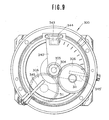
- the throttle actuator 300 comprises a housing 302 which fixedly supports a motor 303.
- a motor rotary shaft 304 of the motor 303 has a gear 305 fixed thereto with a lock pin 308.
- a gear 306 meshes with the gear 305 and another gear 307 and it rotates as the gear 305 rotates and at the same time orbits around the rotary shaft 304 of the motor 303.
- the gear 307 is fixed to the housing 302 by a bolt 309 and a fixer 310. These three gears 305, 306 and 307 cooperate with each other to form a planetary gear mechanism.
- a spindle 31 i.e., a shaft which transmits the rotation of the gear 306 to a rotor 312, which is rotatably inserted into a center hole of the gear 306 via a bearing 314 and axially fixed thereto by a stop 317 and a E-ring 318 via spacers 315 and 316, respectively.
- the spindle 311 has on its one end a projection 319 fixedly inserted into a recess 320 formed in the rotor 312 so as to rotate the rotor 312 as the spindle 311 orbits.
- the rotor 312, an electromagnetic coil 324 and a yoke 325 made of a magnetic material cooperate to form an electromagnetic clutch mechanism.
- the rotor 312 has mounted thereon a clutch facing 326.
- a throttle shaft 327 is rotatably supported by the housing 302 via a bearing 328 and it is axially fixed thereto by an E-ring 329 and a C-ring 330.
- the throttle shaft 327 has one end portion 327a attached to a throttle valve 31 and an opposite end portion 327b inserted in a center hole 333 of the rotor 312 via a bushing 332.
- the throttle shaft 327 has an integral clutch disc 334 facing the rotor 312 on its clutch facing 326.
- the rotor 312 is formed with a ring like groove 335 having attached therein a coil return spring 336.
- the coil return spring 336 having one end fixedly attached to the rotor 312 an opposite end fixedly attached to the clutch disc 334 and biases the clutch disc 334 clockwise as viewed in Fig. 9 and the rotor 312 counterclockwiseas viewed in Fig. 9.
- the reference numeral 40 denotes a slit plate attached to the throttle shaft 327 by a bolt 342 via a spacer 34 1 as illustrated.
- the reference numeral 343 denotes a photo interruptor composed of a semiconductive photo emitter and a-semiconductive photo receiver.
- a rectangular slit plate 344 (see Fig. 10) is mounted on the photo interruptor 343 and formed with a single slit so as to prevent the scattering a light beam.
- the reference numerals 345, 345' denote stop pins, respectively, which are arranged to limit the rotational angle of the rotor 312.
- the d.c. motor 303 When the ignition switch is turned ON, the d.c. motor 303 is actuated to rotate clockwise as viewed in Fig. 9 under a command from the control unit 100. Rotation of the motor 303 is transmitted by the gear 305 fixed to the motor shaft 304 to the gear 306. Owing to the fact that the gear 306 meshes also with the gear 307, the gear 306 orbits around the motor shaft 304 clockwise as viewed in Fig. 9 while turning counterclockwise until it assumes a position as indicated by the phantom line in Fig. 9. When the spindle 311 has come to contact with the stop pin 345, the current supply to the motor 303 is cut off and then the current supply to the coil 324 is started, energizing the coil 324.
- the energization of the coil 324 causes the rotor 312 to be attracted toward the clutch disc 334, thereby bring the clutch facing 326 into contact with the clutch disc 334.
- the slit plate 340 attached to the throttle shaft 327 stays in the state as illustrated in Fig. 9 because the bushing 332 disposed between the rotor 312 and the throttle shaft 327 allows the rotor 312 to rotate relative to the throttle shaft 327.
- the throttle valve 31 remains in its fully closed state during the above described process of actuation.
- the electromagnetic clutch when engaged, acts to establish a driving power transmitting path from the motor 303 to the throttle shaft 327.
- the throttle shaft 327 will not vibrate in actuating the motor 303 to rotate the spindle 311 of the rotor 312 from the position as indicated by the fully drawn line in Fig. 9 to the position as indicated by the phantom line in Fig. 9 because the driving force of the motor 303 is not transmitted to the throttle shaft 327.
- the electromagnetic clutch is turned ON, there takes place no effect of the restoring force of the return spring 336 on the driving force transmission system (, i.e., motor 303, gears 305, 306, 307, shaft 311, rotor 312).
- the spindle 311 of the rotor 312 assumes the position as indicated by the phantom line in Fig. 9. In this state, the throttle valve 31 is still fully closed. Opening of the throttle valve 31 is carried out by actuating the motor 303 with the electromagnetic clutch kept engaged. Describing more in detail, when the motor 303 is actuated to rotate, its driving force is transmitted to the gear 306 by the gear 305. Since the gear 306 meshes with the gear 307 also, it orbits around the rotary shaft 304 of the motor 303 while turning about its axis. The orbiting of the gear 306 causes the spindle 311 to orbit around the rotary shaft 304 (or around the throttle shaft 327).
- the orbiting of the spindle 311 causes the rotor 312 to rotate. Since the clutch disc 334 is kept engaged with the clutch facing 326, rotation of the rotor 312 causes the throttle shaft 327 to rotate, thereby to cause the throttle valve 31 to open to a desired position.
- the current for actuating the motor 303 is cut off or disappears. Since the inertia from the gear 306 to the motor 303 is greater than the inlet manifold vacuum which the throttle valve 31 is subject to, the throttle valve 31 is prevented from fluttering.
- the actuation for opening the throttle valve 31 has been described, the actuation for closing the throttle valve is carried out in the similar manner.
- the slit plates 340 and 344 which cooperate with the photo interruptor 343 to form a throttle position sensor, they are manufactured in the same manner as commercially available ones used in rotary encoders are manufactured. They may be manufactured by vacuum evaporating a metal, such as a chromium, on a glass or blanking a stainless plate.
- the slit plate 340 is so arranged that slits thereof are adapted to pass the light axis of the photo interruptor 343.
- the output signal of the photo interruptor 343 changes, and this change is detected and processed so as to detect the position assumed by the throttle valve 31.
- the electromagnetic clutch of the throttle actuator 24 exhibits a fail-safe function in cooperation with the return spring 336. Next, this fail-safe function is described.
- the return spring 336 exhibits restoring force large enough to prevent the throttle valve 31 from fluttering owing to the inlet manifold vacuum.
- the restoring force of the return spring 336 does not affect the driving power transmitting system until it closes the throttle valve 31 because the driving power transmitting system from the gear 306 to the motor 303 has sufficiently large inertia.
- the restoring force of the return spring 336 affects on the driving power transmitting system, thereby to bring the throttle actuator 24 to assume the position as indicated by the fully drawn line shown in Fig. 9.
- the throttle actuator 300 can resume its ordinary working state after the removal of fail-safe causes.
- the throttle actuator 300 will assume the fully drawn position as shown in Fig. 9 irrespective of its working state when the ignition switch is turned OFF.
- a print motor is used as the motor 3 in the case of Figs. 8 and 9, it is not necessary to limit to this type of motor and other motors of various types may be used such as a DC motor, an AC motor, and a stepper motor.
- zero degree (0°) is set when the spindle 311 is in the position illustrated by the phantom line in Fig. 9 and the output signal from the throttle position sensor (343, 340, 344) is added (count-up) one after another until the throttle valve 31 assumes the desired opening degree.
- the output signal from the throttle position sensor may be added one after another (count-up).
- zero degree (0°) may be set when the throttle valve 31 assumes the one opening degree and the output signal from the throttle position sensor is added one after another (count-up) until the throttle valve 31 assumes the another opening degree.
- the direction of rotation of the throttle valve 31 it can be detected by detecting the driving signal or current supplied to the motor 303.
- the direction of rotation of the throttle valve 31 may be detected by replacing the slit plates 340, 344 with a slit plate 340A and a slit plate 344A as shown in Figs. 11 and 12.
- the slit plate 340A is different from the slit plate 340 in that outer and inner rows of slits are formed. The arrangement is such that each of the slits of the inner row is equidistant in angular direction from the adjacent two slits of the outer row.
- the slit plate 344A is different from the slit plate 344 in that outer and inner slits are formed as best seen in Fig. 12.
- the throttle position sensor employing these slit plates 340A and 344A generates two output signals with 90° phase difference. By suitably processing the two output signals, the direction rotation of the throttle valve 31 can be detected.
Landscapes
- Engineering & Computer Science (AREA)
- Mechanical Engineering (AREA)
- Chemical & Material Sciences (AREA)
- Combustion & Propulsion (AREA)
- General Engineering & Computer Science (AREA)
- Transportation (AREA)
- Physics & Mathematics (AREA)
- Electromagnetism (AREA)
- Automation & Control Theory (AREA)
- Fluid Mechanics (AREA)
- Control Of Throttle Valves Provided In The Intake System Or In The Exhaust System (AREA)
- Electrical Control Of Air Or Fuel Supplied To Internal-Combustion Engine (AREA)
- Control Of Vehicle Engines Or Engines For Specific Uses (AREA)
Priority Applications (1)
| Application Number | Priority Date | Filing Date | Title |
|---|---|---|---|
| DE8686117450T DE3480227D1 (en) | 1983-03-11 | 1984-03-08 | Throttle actuator for an internal combustion engine |
Applications Claiming Priority (4)
| Application Number | Priority Date | Filing Date | Title |
|---|---|---|---|
| JP58039085A JPS59165836A (ja) | 1983-03-11 | 1983-03-11 | スロットルアクチュエ−タ |
| JP39085/83 | 1983-03-11 | ||
| JP188474/83 | 1983-10-11 | ||
| JP58188474A JPS6081559A (ja) | 1983-10-11 | 1983-10-11 | エンジン・無段変速機の制御装置 |
Related Child Applications (1)
| Application Number | Title | Priority Date | Filing Date |
|---|---|---|---|
| EP86117450.6 Division-Into | 1986-12-15 |
Publications (3)
| Publication Number | Publication Date |
|---|---|
| EP0123083A2 true EP0123083A2 (de) | 1984-10-31 |
| EP0123083A3 EP0123083A3 (en) | 1984-12-19 |
| EP0123083B1 EP0123083B1 (de) | 1987-11-04 |
Family
ID=26378410
Family Applications (2)
| Application Number | Title | Priority Date | Filing Date |
|---|---|---|---|
| EP84102527A Expired EP0123083B1 (de) | 1983-03-11 | 1984-03-08 | Steuerungssystem und Steuerungsverfahren für ein Kraftfahrzeug |
| EP86117450A Expired EP0226999B1 (de) | 1983-03-11 | 1984-03-08 | Drosselklappensteuerungsvorrichtung für eine Verbrennungskraftmaschine |
Family Applications After (1)
| Application Number | Title | Priority Date | Filing Date |
|---|---|---|---|
| EP86117450A Expired EP0226999B1 (de) | 1983-03-11 | 1984-03-08 | Drosselklappensteuerungsvorrichtung für eine Verbrennungskraftmaschine |
Country Status (3)
| Country | Link |
|---|---|
| US (1) | US4735114A (de) |
| EP (2) | EP0123083B1 (de) |
| DE (1) | DE3467127D1 (de) |
Cited By (10)
| Publication number | Priority date | Publication date | Assignee | Title |
|---|---|---|---|---|
| DE3527449A1 (de) * | 1984-08-03 | 1986-02-13 | Nissan Motor Co., Ltd., Yokohama, Kanagawa | Regelsystem fuer ein kraftfahrzeug mit stufenlos verstellbarem getriebe |
| GB2181197A (en) * | 1985-09-30 | 1987-04-15 | Aisin Seiki | Control system for engine and cvt |
| GB2181196A (en) * | 1985-09-30 | 1987-04-15 | Aisin Seiki | Control system for engine and cvt |
| FR2607191A1 (fr) * | 1986-11-22 | 1988-05-27 | Bosch Gmbh Robert | Actionneur pour le reglage d'une butee accouplee a un organe de commande d'un moteur a combustion interne |
| EP0210404B1 (de) * | 1985-07-25 | 1989-07-26 | MAN Technologie Aktiengesellschaft | Antriebsstrang für Kraftfahrzeuge |
| EP0386746A1 (de) * | 1989-03-08 | 1990-09-12 | Nissan Motor Co., Ltd. | Getriebesteuerung |
| US4960182A (en) * | 1987-07-02 | 1990-10-02 | Mitsubishi Denki Kabushiki Kaisha | Constant speed holding apparatus |
| EP0482285A1 (de) * | 1990-10-24 | 1992-04-29 | VDO Adolf Schindling AG | Arretierungsvorrichtung |
| FR2688546A1 (fr) * | 1992-03-10 | 1993-09-17 | Siemens Automotive Sa | Procede et dispositif de commande d'un moteur a combustion interne. |
| EP0879731A3 (de) * | 1997-05-22 | 2000-11-15 | Nissan Motor Company, Limited | Integiertes Steuersystem für elektronisch gesteuerte Brennkraftmachine und stufenloses Automatikgetriebe |
Families Citing this family (37)
| Publication number | Priority date | Publication date | Assignee | Title |
|---|---|---|---|---|
| JP2789579B2 (ja) * | 1986-11-18 | 1998-08-20 | 日産自動車株式会社 | 無段変速機の変速制御装置 |
| US4922424A (en) * | 1987-04-20 | 1990-05-01 | Mitsubishi Jidosha Kogyo Kabushiki Kaisha | Control method for a driving system provided in a vehicle |
| JP2784919B2 (ja) * | 1987-08-10 | 1998-08-13 | スズキ株式会社 | 連続可変変速機制御方法 |
| GB2219637B (en) * | 1988-06-08 | 1992-05-06 | Mitsubishi Electric Corp | Electromagnetic clutch in motor-powered drive device |
| JP2882528B2 (ja) * | 1988-07-20 | 1999-04-12 | 本田技研工業株式会社 | 無段変速機のスロットル制御付き変速制御方法 |
| JP2581782B2 (ja) * | 1988-11-28 | 1997-02-12 | 日産自動車株式会社 | 自動変速機の変速制御装置 |
| JP2568923B2 (ja) * | 1989-10-16 | 1997-01-08 | 本田技研工業株式会社 | 無段変速機の制御方法 |
| JPH03189461A (ja) * | 1989-12-18 | 1991-08-19 | Mazda Motor Corp | 無段変速機の変速比制御装置 |
| JP3200901B2 (ja) * | 1991-12-20 | 2001-08-20 | 株式会社日立製作所 | 電気自動車の駆動装置 |
| JP3318945B2 (ja) * | 1992-03-02 | 2002-08-26 | 株式会社日立製作所 | 自動車用制御装置、自動車制御システム及び自動車の制御方法 |
| JPH07507977A (ja) * | 1992-05-08 | 1995-09-07 | フィールド,ブルース エフ. | 電気ハイブリッド車両 |
| JPH07174219A (ja) * | 1993-12-20 | 1995-07-11 | Hitachi Ltd | 車両用変速装置 |
| DE4411938A1 (de) * | 1994-04-07 | 1995-10-12 | Porsche Ag | Steuereinrichtung und Steuerverfahren für ein stufenloses Getriebe |
| JP3461572B2 (ja) * | 1994-06-09 | 2003-10-27 | 株式会社日立ユニシアオートモティブ | 車両の制御装置 |
| JP3404934B2 (ja) * | 1994-12-05 | 2003-05-12 | トヨタ自動車株式会社 | 無段変速機付車両の制御装置 |
| DE19546651A1 (de) * | 1995-12-14 | 1997-06-19 | Fev Motorentech Gmbh & Co Kg | Verfahren zum Betreiben eines Fahrzeugs mit stufenlos verstellbarem Getriebe |
| DE19611804A1 (de) * | 1996-03-26 | 1997-10-02 | Bosch Gmbh Robert | Vorrichtung zur Einstellung einer Übersetzung eines kontinuierlich verstellbaren Getriebes |
| DE19744218C1 (de) | 1997-10-07 | 1999-04-22 | Zahnradfabrik Friedrichshafen | Antriebsstrangsteuerung |
| JPH11198686A (ja) * | 1998-01-09 | 1999-07-27 | Honda Motor Co Ltd | 車両用駆動力制御装置 |
| US6066070A (en) * | 1998-04-28 | 2000-05-23 | Toyota Jidosha Kabushiki Kaisha | Control system of vehicle having continuously variable transmission |
| JP3460576B2 (ja) * | 1998-04-28 | 2003-10-27 | トヨタ自動車株式会社 | 無段変速機を備えた車両の制御装置 |
| US6436005B1 (en) | 1998-06-18 | 2002-08-20 | Cummins, Inc. | System for controlling drivetrain components to achieve fuel efficiency goals |
| US6387011B1 (en) * | 1998-06-18 | 2002-05-14 | Cummins, Inc. | System for controlling an internal combustion engine in a fuel efficient manner |
| DE19827133A1 (de) * | 1998-06-18 | 1999-12-23 | Volkswagen Ag | Triebstrangmanagement für ein Kraftfahrzeug |
| JP3577966B2 (ja) * | 1998-09-07 | 2004-10-20 | 日産自動車株式会社 | 車両の駆動力制御装置 |
| JP3815111B2 (ja) * | 1999-04-16 | 2006-08-30 | 日産自動車株式会社 | 車両の駆動力制御装置 |
| JP3546302B2 (ja) * | 1999-08-05 | 2004-07-28 | トヨタ自動車株式会社 | 無段変速機を備えた車両の制御装置 |
| DE19961312C1 (de) * | 1999-12-18 | 2001-06-28 | Bayerische Motoren Werke Ag | Verfahren und Vorrichtung zur Steuerung eines stufenlosen Automatikgetriebes |
| JP3666391B2 (ja) * | 2000-12-26 | 2005-06-29 | 日産自動車株式会社 | 駆動力制御装置 |
| JP3617502B2 (ja) * | 2002-04-11 | 2005-02-09 | 日産自動車株式会社 | 車線逸脱防止装置 |
| DE102004031312A1 (de) * | 2004-06-29 | 2006-02-02 | Robert Bosch Gmbh | Verfahren zum Betreiben einer Antriebseinrichtung |
| JP4428163B2 (ja) * | 2004-07-20 | 2010-03-10 | 株式会社デンソー | バルブ位置制御装置 |
| FR2911556B1 (fr) * | 2007-01-24 | 2009-08-28 | Renault Sas | Procede de controle du fonctionnement d'un groupe moto-propulseur. |
| US8606474B2 (en) * | 2007-06-11 | 2013-12-10 | Cummins Inc. | Continuous variable transmission system |
| US8172202B2 (en) | 2009-04-24 | 2012-05-08 | Honeywell International Inc. | Butterfly valve assembly including a bearing assembly for serrated spline constraint |
| JP5729489B2 (ja) * | 2011-12-28 | 2015-06-03 | トヨタ自動車株式会社 | 減速因子推定装置 |
| EP2810840B1 (de) | 2012-02-03 | 2019-08-07 | Toyota Jidosha Kabushiki Kaisha | Vorrichtung zur schätzung des abbremsfaktors |
Citations (10)
| Publication number | Priority date | Publication date | Assignee | Title |
|---|---|---|---|---|
| US3527118A (en) * | 1968-07-10 | 1970-09-08 | Us Navy | Selective automatic and manual throttle actuator |
| GB1556888A (en) * | 1976-03-22 | 1979-11-28 | Fiat Spa | Method of automatic control for motor vehicles |
| GB2057605A (en) * | 1979-08-24 | 1981-04-01 | Zahnradfabrik Friedrichshafen | Control devices for variable transmissions |
| JPS5790450A (en) * | 1980-11-27 | 1982-06-05 | Nippon Denso Co Ltd | Automatic change gear control apparatus for vehicle |
| US4343385A (en) * | 1979-03-07 | 1982-08-10 | Nippon Soken, Inc. | Automatic drive mechanism for vehicles |
| EP0059426A2 (de) * | 1981-02-24 | 1982-09-08 | Nissan Motor Co., Ltd. | Steuervorrichtung für Lastkraftwagen |
| EP0061735A2 (de) * | 1981-03-28 | 1982-10-06 | Nissan Motor Co., Ltd. | Steuerungssystem für stufenlos regelbare Riemengetriebe |
| US4360089A (en) * | 1979-07-04 | 1982-11-23 | Nippon Soken, Inc. | Electric actuator provided with a brake |
| US4365152A (en) * | 1978-10-03 | 1982-12-21 | Franc Gergek | Encoder for machine control |
| EP0073475A2 (de) * | 1981-08-27 | 1983-03-09 | Nissan Motor Co., Ltd. | Vorrichtung und Verfahren zum Steuern eines Motors und eines stufenlos regelbares Wechselgetriebes |
Family Cites Families (12)
| Publication number | Priority date | Publication date | Assignee | Title |
|---|---|---|---|---|
| US3113473A (en) * | 1963-12-10 | morlen | ||
| GB1525861A (en) * | 1975-10-23 | 1978-09-20 | Mullard Ltd | Vehicle power transmission arrangements and electronic control means therefor |
| FR2385902A1 (fr) * | 1977-03-31 | 1978-10-27 | Renault | Procede de regulation d'un groupe moto-propulseur et dispositif permettant sa mise en oeuvre |
| DE2843256A1 (de) * | 1978-10-04 | 1980-04-17 | Bosch Gmbh Robert | Vorrichtung zur regelung einer kraftfahrzeug-antriebseinheit |
| JPS5675935A (en) * | 1979-11-26 | 1981-06-23 | Nippon Denso Co Ltd | Speed governor for automobile |
| US4287969A (en) * | 1979-12-21 | 1981-09-08 | Nhk Spring Co., Ltd. | Motion snubbing device |
| JPS56107925A (en) * | 1980-01-31 | 1981-08-27 | Mikuni Kogyo Co Ltd | Electronically controlled fuel injector for ignited internal combustion engine |
| JPS56132428A (en) * | 1980-03-19 | 1981-10-16 | Hitachi Ltd | Controller of intake air amount to internal combustion engine |
| WO1982000271A1 (en) * | 1980-07-10 | 1982-02-04 | Weston P | Transmission system |
| DE3050625A1 (en) * | 1980-10-31 | 1982-11-18 | Yves J Kemper | Method of vehicle propulsion |
| US4457354A (en) * | 1981-08-03 | 1984-07-03 | International Telephone And Telegraph Corporation | Mold for use in metal or metal alloy casting systems |
| US4458560A (en) * | 1982-05-21 | 1984-07-10 | Aisin Seiki Kabushiki Kaisha | Control system and method for a power delivery system having a continuously variable ratio transmission |
-
1984
- 1984-03-08 DE DE8484102527T patent/DE3467127D1/de not_active Expired
- 1984-03-08 EP EP84102527A patent/EP0123083B1/de not_active Expired
- 1984-03-08 EP EP86117450A patent/EP0226999B1/de not_active Expired
-
1986
- 1986-10-02 US US06/914,520 patent/US4735114A/en not_active Expired - Lifetime
Patent Citations (10)
| Publication number | Priority date | Publication date | Assignee | Title |
|---|---|---|---|---|
| US3527118A (en) * | 1968-07-10 | 1970-09-08 | Us Navy | Selective automatic and manual throttle actuator |
| GB1556888A (en) * | 1976-03-22 | 1979-11-28 | Fiat Spa | Method of automatic control for motor vehicles |
| US4365152A (en) * | 1978-10-03 | 1982-12-21 | Franc Gergek | Encoder for machine control |
| US4343385A (en) * | 1979-03-07 | 1982-08-10 | Nippon Soken, Inc. | Automatic drive mechanism for vehicles |
| US4360089A (en) * | 1979-07-04 | 1982-11-23 | Nippon Soken, Inc. | Electric actuator provided with a brake |
| GB2057605A (en) * | 1979-08-24 | 1981-04-01 | Zahnradfabrik Friedrichshafen | Control devices for variable transmissions |
| JPS5790450A (en) * | 1980-11-27 | 1982-06-05 | Nippon Denso Co Ltd | Automatic change gear control apparatus for vehicle |
| EP0059426A2 (de) * | 1981-02-24 | 1982-09-08 | Nissan Motor Co., Ltd. | Steuervorrichtung für Lastkraftwagen |
| EP0061735A2 (de) * | 1981-03-28 | 1982-10-06 | Nissan Motor Co., Ltd. | Steuerungssystem für stufenlos regelbare Riemengetriebe |
| EP0073475A2 (de) * | 1981-08-27 | 1983-03-09 | Nissan Motor Co., Ltd. | Vorrichtung und Verfahren zum Steuern eines Motors und eines stufenlos regelbares Wechselgetriebes |
Cited By (14)
| Publication number | Priority date | Publication date | Assignee | Title |
|---|---|---|---|---|
| DE3527449A1 (de) * | 1984-08-03 | 1986-02-13 | Nissan Motor Co., Ltd., Yokohama, Kanagawa | Regelsystem fuer ein kraftfahrzeug mit stufenlos verstellbarem getriebe |
| EP0210404B1 (de) * | 1985-07-25 | 1989-07-26 | MAN Technologie Aktiengesellschaft | Antriebsstrang für Kraftfahrzeuge |
| GB2181196B (en) * | 1985-09-30 | 1990-05-23 | Aisin Seiki | Control systems for engine and cvt |
| GB2181197A (en) * | 1985-09-30 | 1987-04-15 | Aisin Seiki | Control system for engine and cvt |
| GB2181196A (en) * | 1985-09-30 | 1987-04-15 | Aisin Seiki | Control system for engine and cvt |
| GB2181197B (en) * | 1985-09-30 | 1990-05-23 | Aisin Seiki | Control systems for engine and cvt |
| FR2607191A1 (fr) * | 1986-11-22 | 1988-05-27 | Bosch Gmbh Robert | Actionneur pour le reglage d'une butee accouplee a un organe de commande d'un moteur a combustion interne |
| US4960182A (en) * | 1987-07-02 | 1990-10-02 | Mitsubishi Denki Kabushiki Kaisha | Constant speed holding apparatus |
| EP0386746A1 (de) * | 1989-03-08 | 1990-09-12 | Nissan Motor Co., Ltd. | Getriebesteuerung |
| US5103693A (en) * | 1989-03-08 | 1992-04-14 | Nissan Motor Co., Ltd. | Control system for transmission |
| EP0482285A1 (de) * | 1990-10-24 | 1992-04-29 | VDO Adolf Schindling AG | Arretierungsvorrichtung |
| US5148787A (en) * | 1990-10-24 | 1992-09-22 | Vdo Adolf Schindling Ag | Retention device |
| FR2688546A1 (fr) * | 1992-03-10 | 1993-09-17 | Siemens Automotive Sa | Procede et dispositif de commande d'un moteur a combustion interne. |
| EP0879731A3 (de) * | 1997-05-22 | 2000-11-15 | Nissan Motor Company, Limited | Integiertes Steuersystem für elektronisch gesteuerte Brennkraftmachine und stufenloses Automatikgetriebe |
Also Published As
| Publication number | Publication date |
|---|---|
| EP0226999B1 (de) | 1989-10-18 |
| EP0226999A2 (de) | 1987-07-01 |
| EP0226999A3 (en) | 1987-09-02 |
| DE3467127D1 (en) | 1987-12-10 |
| EP0123083B1 (de) | 1987-11-04 |
| US4735114A (en) | 1988-04-05 |
| EP0123083A3 (en) | 1984-12-19 |
Similar Documents
| Publication | Publication Date | Title |
|---|---|---|
| EP0123083A2 (de) | Steuerungssystem und Steuerungsverfahren für ein Kraftfahrzeug | |
| US4261229A (en) | Automatic speed ratio control system for stepless transmission of automotive vehicles | |
| US5366424A (en) | Power train control system for internal combustion engine of motor vehicle | |
| US4220059A (en) | Speed ratio control system for stepless transmission of vehicles | |
| US5215057A (en) | Electrically-operated throttle actuator | |
| US4916982A (en) | Improvements in controls relating to engine braking in a continuously variable transmission | |
| US4727840A (en) | Throttle valve control device | |
| JPH03125032A (ja) | 自動発進クラッチの制御装置 | |
| EP0421183B1 (de) | Steuerungssystem für ein stufenloses Getriebe | |
| JPH02304262A (ja) | 自動変速機のライン圧制御装置 | |
| US4995363A (en) | Throttle controller | |
| US5249482A (en) | Ratio control for continuously variable transmission | |
| JP3627276B2 (ja) | 自動変速機の変速制御装置 | |
| JP3998135B2 (ja) | 無段変速機の変速比制御装置 | |
| JPH0270932A (ja) | スロットル制御装置 | |
| JP3427736B2 (ja) | 無段変速機の変速制御装置 | |
| JP4120213B2 (ja) | 車両の駆動力制御装置 | |
| US5209318A (en) | Constant-speed cruising system for a vehicle | |
| JP2582457B2 (ja) | 内燃機関のスロットル弁制御装置 | |
| US5293855A (en) | Electronic throttle valve drive unit | |
| JP3070536B2 (ja) | 車両のエンジン・自動変速機の制御装置 | |
| JP3427741B2 (ja) | トロイダル型無段変速機の変速制御装置 | |
| JP3975524B2 (ja) | 車両用駆動力制御装置 | |
| JP3323969B2 (ja) | 自動変速機の出力制御装置 | |
| JPH0370637A (ja) | エンジン・無段変速機駆動系統の制御装置 |
Legal Events
| Date | Code | Title | Description |
|---|---|---|---|
| PUAI | Public reference made under article 153(3) epc to a published international application that has entered the european phase |
Free format text: ORIGINAL CODE: 0009012 |
|
| PUAL | Search report despatched |
Free format text: ORIGINAL CODE: 0009013 |
|
| 17P | Request for examination filed |
Effective date: 19840308 |
|
| AK | Designated contracting states |
Designated state(s): DE FR GB IT |
|
| AK | Designated contracting states |
Designated state(s): DE FR GB IT |
|
| RAP1 | Party data changed (applicant data changed or rights of an application transferred) |
Owner name: NISSAN MOTOR CO., LTD. |
|
| 17Q | First examination report despatched |
Effective date: 19860822 |
|
| GRAA | (expected) grant |
Free format text: ORIGINAL CODE: 0009210 |
|
| AK | Designated contracting states |
Kind code of ref document: B1 Designated state(s): DE FR GB IT |
|
| REF | Corresponds to: |
Ref document number: 3467127 Country of ref document: DE Date of ref document: 19871210 |
|
| ITF | It: translation for a ep patent filed |
Owner name: SOCIETA' ITALIANA BREVETTI S.P.A. |
|
| ET | Fr: translation filed | ||
| PLBE | No opposition filed within time limit |
Free format text: ORIGINAL CODE: 0009261 |
|
| STAA | Information on the status of an ep patent application or granted ep patent |
Free format text: STATUS: NO OPPOSITION FILED WITHIN TIME LIMIT |
|
| 26N | No opposition filed | ||
| PGFP | Annual fee paid to national office [announced via postgrant information from national office to epo] |
Ref country code: FR Payment date: 19910307 Year of fee payment: 8 |
|
| ITTA | It: last paid annual fee | ||
| PG25 | Lapsed in a contracting state [announced via postgrant information from national office to epo] |
Ref country code: FR Effective date: 19921130 |
|
| REG | Reference to a national code |
Ref country code: FR Ref legal event code: ST |
|
| REG | Reference to a national code |
Ref country code: GB Ref legal event code: IF02 |
|
| PGFP | Annual fee paid to national office [announced via postgrant information from national office to epo] |
Ref country code: GB Payment date: 20030305 Year of fee payment: 20 |
|
| PGFP | Annual fee paid to national office [announced via postgrant information from national office to epo] |
Ref country code: DE Payment date: 20030320 Year of fee payment: 20 |
|
| PG25 | Lapsed in a contracting state [announced via postgrant information from national office to epo] |
Ref country code: GB Free format text: LAPSE BECAUSE OF EXPIRATION OF PROTECTION Effective date: 20040307 |
|
| REG | Reference to a national code |
Ref country code: GB Ref legal event code: PE20 |