EP0118454B1 - Bobine d'allumage pour moteurs a combustion interne - Google Patents
Bobine d'allumage pour moteurs a combustion interne Download PDFInfo
- Publication number
- EP0118454B1 EP0118454B1 EP83901931A EP83901931A EP0118454B1 EP 0118454 B1 EP0118454 B1 EP 0118454B1 EP 83901931 A EP83901931 A EP 83901931A EP 83901931 A EP83901931 A EP 83901931A EP 0118454 B1 EP0118454 B1 EP 0118454B1
- Authority
- EP
- European Patent Office
- Prior art keywords
- branch
- sheets
- ignition coil
- circuit
- magnetic circuit
- Prior art date
- Legal status (The legal status is an assumption and is not a legal conclusion. Google has not performed a legal analysis and makes no representation as to the accuracy of the status listed.)
- Expired
Links
Images
Classifications
-
- H—ELECTRICITY
- H01—ELECTRIC ELEMENTS
- H01F—MAGNETS; INDUCTANCES; TRANSFORMERS; SELECTION OF MATERIALS FOR THEIR MAGNETIC PROPERTIES
- H01F3/00—Cores, Yokes, or armatures
- H01F3/10—Composite arrangements of magnetic circuits
- H01F3/14—Constrictions; Gaps, e.g. air-gaps
-
- H—ELECTRICITY
- H01—ELECTRIC ELEMENTS
- H01F—MAGNETS; INDUCTANCES; TRANSFORMERS; SELECTION OF MATERIALS FOR THEIR MAGNETIC PROPERTIES
- H01F27/00—Details of transformers or inductances, in general
- H01F27/24—Magnetic cores
- H01F27/245—Magnetic cores made from sheets, e.g. grain-oriented
-
- H—ELECTRICITY
- H01—ELECTRIC ELEMENTS
- H01F—MAGNETS; INDUCTANCES; TRANSFORMERS; SELECTION OF MATERIALS FOR THEIR MAGNETIC PROPERTIES
- H01F38/00—Adaptations of transformers or inductances for specific applications or functions
- H01F38/12—Ignition, e.g. for IC engines
Definitions
- the present invention relates to an ignition coil, for internal combustion engines, ignition coil comprising: a closed magnetic circuit consisting of sheets cut and stacked on each other; a permanent magnet disposed in a branch of thickness E of said circuit; the enroute - primary and secondary elements housed in an insulating housing surrounding a branch other thickness E '.
- This ignition coil has a circuit for bypassing the magnetic flux, so that the flux reversal created in the branch, of thickness E ′, by the current flowing in the primary winding, does not demagnetize the permanent magnet .
- This magnetic flux bypass circuit consists of two sheets of mild steel, which sheets have a tab provided with a hole, or an opening, receiving one of the fixing screws of the ignition coil on the motor vehicle.
- Such known ignition coils in particular by French patent applications: FR-A-2476218 and 2486160, have the disadvantage that to secure, using rivets, the branches of thickness E and E ', it it is necessary to provide an overlap of the ends of the branch E ', which leads to providing a cutting tool for the sheets constituting the branch of thickness E' and three cutting tools for all the sheets constituting the branch E.
- Another drawback is that the magnetic circuit can only be joined after having placed the insulating box, containing the primary and secondary windings, on the branch of thickness E 'and having subsequently stacked a number of sheets of the branch of thickness E, so as to constitute a packet of thickness corresponding to the thickness E '.
- the circuit After which, in a third step, the circuit must be completed by the sheets of the branch of thickness E which ensure the covering of the ends of the branch of thickness E '.
- an ignition coil for internal combustion engines comprising: a closed magnetic circuit (1) consisting of a plurality of sheets cut and stacked one on the other. the others so as to form a rectangular frame with branches of rectangular cross section; a permanent magnet (2) disposed between two half-branches (12b, 13b) defining a first branch (3) of the magnetic circuit; a primary winding (4) and a secondary winding (5) housed in an insulating housing (6) and surrounding a second branch (8) opposite to said first branch (3), coil characterized in that said closed magnetic circuit (1) comprises: a first part (12) U-shaped and having a first thickness (E '); a second L-shaped part (13) having a second thickness (E) greater than said thickness, a branch (12b) of said first part (12) and a branch (13b) of said second part (13) being cut out at a bevel and forming said two half-branches, a magnetic flux bypass circuit consisting of two sheets (9) of mild
- a first advantage obtained by this invention is that the cutting of the sheets of the magnetic circuit requires only one tool per part, which reduces the expenses relating to the cutting tools.
- a second advantage is the reduction in assembly time, due to the fact that the sheets which, in the prior art provided for the joining of the magnetic circuit, by covering the ends of the branch E ', are eliminated, the magnetic circuit being secured by an extension of the sheets constituting the magnetic flux bypass circuit.
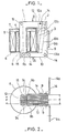
- the ignition coil according to the invention comprises a closed magnetic circuit 1 made up of cut sheets and stacked one on the other.
- a permanent magnet 2 magnetized in the direction of its thickness is placed in a branch 3 of the closed magnetic circuit 1,
- the magnetic flux bypass circuit consists of two sheets 9, made of mild steel, arranged, by means of insulating plates 10 and 11, on both sides and d other planes defining the thickness E of the branch 3.
- the sheets 9, symmetrical cambered comprise a tab 9a, provided with a hole, or with an opening, not shown, so as to ensure the fixing of the ignition coil to the motor vehicle.
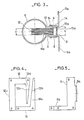
- the closed miagnetic circuit 1 includes a first part 12, figures 1 and 4.
- the first part 12 consists of sheets, cut into a U-shape, comprising a portion 12a cut in a bevel 12b. After stacking the sheets on top of each other, the portion 12a forms a half-branch of the branch 3, and a portion 12c forms the branch 8 of the closed magnetic circuit 1.
- a second part 13, of the closed magnetic circuit 1, FIGS. 1 and 4 consists of sheets cut out in the shape of an L, which sheets include a portion 13a cut out in bevel 13b so as to form the other half-branch of branch 3 .
- the first and second parts 12 and 13 are joined together, using known means, such as rivets 14, 1 and by extensions 9b of the sheets 9 constituting the circuit for deriving the magnetic flux.
- the portion 13a of the second part 13 of the closed magnetic circuit 1 and the permanent magnet 2, FIG. 3 are in contact with the sheets 9 of the magnetic flux bypass circuit so that the air gap reluctance of said circuit is equivalent to the air gap reluctance of the circuit described in the French patent application FR-A-2486160. Consequently, the plates 10 and 11 of the present invention have a thickness equal to 2d relative to the thickness d of the insulating plates of the French patent application FR-A-2486 160.
- the insulating plates 10 and 11 are molded with the insulating housing 6, and their internal faces 1 Oa and 11a constitute a housing for the portion 1 2a of the first part 12 of the closed magnetic circuit 1, FIG. 3.
- the extension 9b of the sheets 9 has a bend 9c, FIG. 2.
Landscapes
- Engineering & Computer Science (AREA)
- Power Engineering (AREA)
- Chemical & Material Sciences (AREA)
- Composite Materials (AREA)
- Ignition Installations For Internal Combustion Engines (AREA)
Applications Claiming Priority (2)
| Application Number | Priority Date | Filing Date | Title |
|---|---|---|---|
| FR8213965 | 1982-08-11 | ||
| FR8213965A FR2531751A1 (fr) | 1982-08-11 | 1982-08-11 | Bobine d'allumage pour moteur a combustion interne |
Publications (2)
| Publication Number | Publication Date |
|---|---|
| EP0118454A1 EP0118454A1 (fr) | 1984-09-19 |
| EP0118454B1 true EP0118454B1 (fr) | 1987-01-07 |
Family
ID=9276796
Family Applications (1)
| Application Number | Title | Priority Date | Filing Date |
|---|---|---|---|
| EP83901931A Expired EP0118454B1 (fr) | 1982-08-11 | 1983-07-01 | Bobine d'allumage pour moteurs a combustion interne |
Country Status (14)
| Country | Link |
|---|---|
| US (1) | US4546753A (OSRAM) |
| EP (1) | EP0118454B1 (OSRAM) |
| DE (1) | DE3369027D1 (OSRAM) |
| ES (1) | ES273881Y (OSRAM) |
| FR (1) | FR2531751A1 (OSRAM) |
| IL (1) | IL69457A (OSRAM) |
| IT (1) | IT1168780B (OSRAM) |
| MA (1) | MA19865A1 (OSRAM) |
| OA (1) | OA07655A (OSRAM) |
| PT (1) | PT77076B (OSRAM) |
| RO (1) | RO88098A (OSRAM) |
| SU (1) | SU1292671A3 (OSRAM) |
| UA (1) | UA7144A1 (OSRAM) |
| WO (1) | WO1984000843A1 (OSRAM) |
Families Citing this family (16)
| Publication number | Priority date | Publication date | Assignee | Title |
|---|---|---|---|---|
| DE3619984A1 (de) * | 1986-06-13 | 1987-12-17 | Bosch Gmbh Robert | Zuendspule fuer zuendanlagen von brennkraftmaschinen |
| ES2040409T3 (es) * | 1988-07-28 | 1993-10-16 | Nippondenso Co., Ltd. | Bobina de ignicion. |
| JPH03149805A (ja) * | 1989-11-07 | 1991-06-26 | Aisan Ind Co Ltd | 内燃機関用点火コイル |
| JPH04143461A (ja) * | 1990-10-05 | 1992-05-18 | Honda Motor Co Ltd | 内燃機関の点火装置 |
| US5335642A (en) * | 1992-09-03 | 1994-08-09 | Ford Motor Company | Ignition coil |
| US5285761A (en) * | 1992-09-03 | 1994-02-15 | Ford Motor Company | Ignition coil |
| US5241941A (en) * | 1992-09-03 | 1993-09-07 | Ford Motor Company | Ignition coil |
| US5333593A (en) * | 1993-01-15 | 1994-08-02 | Ford Motor Company | Energy-on-demand ignition coil |
| JPH0845755A (ja) * | 1994-08-02 | 1996-02-16 | Aisan Ind Co Ltd | 内燃機関用点火コイル |
| US5692483A (en) * | 1995-06-30 | 1997-12-02 | Nippondenso Co., Ltd. | Ignition coil used for an internal combustion engine |
| US6118366A (en) * | 1997-12-09 | 2000-09-12 | Siemens Automotive Corporation | Electromagnetic actuator with split housing assembly |
| RU2152534C1 (ru) * | 1998-04-13 | 2000-07-10 | Акционерное общество "АвтоВАЗ" | Катушка зажигания |
| US8289117B2 (en) * | 2010-06-15 | 2012-10-16 | Federal-Mogul Corporation | Ignition coil with energy storage and transformation |
| JP5192531B2 (ja) * | 2010-10-29 | 2013-05-08 | 三菱電機株式会社 | 内燃機関用点火コイル |
| CN110462768B (zh) * | 2017-03-30 | 2022-03-15 | 三菱电机株式会社 | 点火线圈 |
| JP7358839B2 (ja) * | 2019-08-22 | 2023-10-11 | 株式会社デンソー | 点火コイル |
Family Cites Families (9)
| Publication number | Priority date | Publication date | Assignee | Title |
|---|---|---|---|---|
| US1623426A (en) * | 1927-04-05 | Induction coil foe ignition systems | ||
| US1545429A (en) * | 1923-01-12 | 1925-07-07 | Gen Motors Res Corp | Ignition apparatus |
| US1953174A (en) * | 1930-05-28 | 1934-04-03 | Delco Remy Corp | Ignition device |
| GB677051A (en) * | 1949-12-21 | 1952-08-06 | Philips Electrical Ind Ltd | Improvements in or relating to transformers or inductance coils |
| BE505464A (OSRAM) * | 1951-04-23 | |||
| ES425913A1 (es) * | 1974-05-03 | 1976-07-01 | Arjona Vallet | Perfeccionamientos introducidos en la construccion de nu- cleos para reactancias. |
| FR2321054A1 (fr) * | 1975-08-14 | 1977-03-11 | Sev Marchal | Bobine d'allumage |
| FR2476218A1 (fr) * | 1980-02-20 | 1981-08-21 | Ducellier & Cie | Bobine d'allumage pour moteurs a combustion interne |
| FR2486160A1 (fr) * | 1980-07-04 | 1982-01-08 | Ducellier & Cie | Perfectionnement aux bobines d'allumage pour moteurs a combustion interne |
-
1982
- 1982-08-11 FR FR8213965A patent/FR2531751A1/fr active Granted
-
1983
- 1983-07-01 UA UA3723473A patent/UA7144A1/uk unknown
- 1983-07-01 WO PCT/FR1983/000131 patent/WO1984000843A1/fr not_active Ceased
- 1983-07-01 EP EP83901931A patent/EP0118454B1/fr not_active Expired
- 1983-07-01 DE DE8383901931T patent/DE3369027D1/de not_active Expired
- 1983-07-01 US US06/600,638 patent/US4546753A/en not_active Expired - Lifetime
- 1983-07-21 PT PT77076A patent/PT77076B/pt unknown
- 1983-08-03 ES ES1983273881U patent/ES273881Y/es not_active Expired
- 1983-08-09 IL IL69457A patent/IL69457A/xx unknown
- 1983-08-09 IT IT48829/83A patent/IT1168780B/it active
- 1983-08-10 MA MA20087A patent/MA19865A1/fr unknown
-
1984
- 1984-02-10 OA OA58228A patent/OA07655A/xx unknown
- 1984-03-13 RO RO84113914A patent/RO88098A/ro unknown
- 1984-04-09 SU SU843723473A patent/SU1292671A3/ru active
Also Published As
| Publication number | Publication date |
|---|---|
| UA7144A1 (uk) | 1995-06-30 |
| MA19865A1 (fr) | 1984-04-01 |
| ES273881Y (es) | 1985-01-01 |
| WO1984000843A1 (fr) | 1984-03-01 |
| FR2531751A1 (fr) | 1984-02-17 |
| US4546753A (en) | 1985-10-15 |
| FR2531751B1 (OSRAM) | 1984-12-21 |
| RO88098B (ro) | 1985-10-31 |
| IT1168780B (it) | 1987-05-20 |
| RO88098A (ro) | 1985-11-30 |
| DE3369027D1 (en) | 1987-02-12 |
| IL69457A0 (en) | 1983-11-30 |
| IT8348829A1 (it) | 1985-02-09 |
| IL69457A (en) | 1987-09-16 |
| PT77076B (fr) | 1986-01-27 |
| ES273881U (es) | 1984-06-16 |
| OA07655A (fr) | 1985-05-23 |
| EP0118454A1 (fr) | 1984-09-19 |
| PT77076A (fr) | 1983-08-01 |
| SU1292671A3 (ru) | 1987-02-23 |
| IT8348829A0 (it) | 1983-08-09 |
Similar Documents
| Publication | Publication Date | Title |
|---|---|---|
| EP0118454B1 (fr) | Bobine d'allumage pour moteurs a combustion interne | |
| FR2467502A1 (en) | Electric starter motor rotor winding for vehicle - has minimal depth slots with offset conductors to minimise flux distortion | |
| EP0743738B1 (fr) | Alternateur, notamment pour véhicule automobile, comportant un agencement perfectionné de diodes de redressement | |
| EP1618629B1 (fr) | Connecteur electrique intercalaire destine a relier entre eux deux circuits electroniques superposes et son procede de montage | |
| EP0889576A1 (fr) | Moteur linéaire | |
| EP0793870A2 (fr) | Moteur synchrone a aimants permanents | |
| FR3038154A1 (fr) | Machine electrique tournante | |
| CN101630887A (zh) | 永久磁铁同步电动机 | |
| EP0395512B1 (fr) | Bobine d'allumage, en particulier pour moteur à combustion interne de véhicule automobile, et moyens de maintien de l'ensemble primaire dans le secondaire | |
| EP0395511B1 (fr) | Dispositif de fixation d'une bobine d'allumage, en particulier pour moteur à combustion interne de véhicule automobile | |
| US4859892A (en) | Apparatus for securing magnetic poles of magnet-type rotating machines | |
| EP0043744B1 (fr) | Bobine d'allumage pour moteur à combustion interne | |
| FR2523653A1 (fr) | Generateur magnetique pour installations d'allumage de moteurs a combustion interne | |
| JPH10174324A (ja) | 永久磁石回転子 | |
| FR2502836A1 (fr) | Dispositif pour la realisation de bobinages electriques isoles, et procede d'assemblage de ce dispositif | |
| EP0143023B1 (fr) | Bride de maintien du circuit magnétique d'une bobine d'allumage pour véhicule automobile et procédé d'obtention d'une telle bride | |
| EP0743740B1 (fr) | Alternateur, notamment pour véhicule automobile, comportant un agencement de diodes de redressement | |
| EP0102261B1 (fr) | Procédé d'obtention d'une bobine à circuit magnétique fermé et à aimant permanent pour l'allumage de moteurs à combustion interne | |
| FR2483677A1 (fr) | Composants electriques bobines | |
| FR2776856A3 (fr) | Partie a encoches d'un moteur electrique et procede de fabrication de cette partie | |
| FR2476218A1 (fr) | Bobine d'allumage pour moteurs a combustion interne | |
| JP3741386B2 (ja) | 磁石発電機の回転子 | |
| KR890012426A (ko) | 영구자석형 스탭모터 | |
| CH209737A (fr) | Noyau magnétique feuilleté à pôles imbriqués pour machine électrique. | |
| EP0328459A1 (fr) | Tête magnétique à aimant permanent |
Legal Events
| Date | Code | Title | Description |
|---|---|---|---|
| PUAI | Public reference made under article 153(3) epc to a published international application that has entered the european phase |
Free format text: ORIGINAL CODE: 0009012 |
|
| 17P | Request for examination filed |
Effective date: 19840601 |
|
| AK | Designated contracting states |
Designated state(s): BE DE GB |
|
| GRAA | (expected) grant |
Free format text: ORIGINAL CODE: 0009210 |
|
| AK | Designated contracting states |
Kind code of ref document: B1 Designated state(s): BE DE GB |
|
| ITF | It: translation for a ep patent filed | ||
| REF | Corresponds to: |
Ref document number: 3369027 Country of ref document: DE Date of ref document: 19870212 |
|
| PLBE | No opposition filed within time limit |
Free format text: ORIGINAL CODE: 0009261 |
|
| STAA | Information on the status of an ep patent application or granted ep patent |
Free format text: STATUS: NO OPPOSITION FILED WITHIN TIME LIMIT |
|
| 26N | No opposition filed | ||
| PG25 | Lapsed in a contracting state [announced via postgrant information from national office to epo] |
Ref country code: BE Effective date: 19880731 |
|
| BERE | Be: lapsed |
Owner name: DUCELLIER ET CIE Effective date: 19880731 |
|
| PGFP | Annual fee paid to national office [announced via postgrant information from national office to epo] |
Ref country code: GB Payment date: 20010626 Year of fee payment: 19 |
|
| PGFP | Annual fee paid to national office [announced via postgrant information from national office to epo] |
Ref country code: DE Payment date: 20010717 Year of fee payment: 19 |
|
| REG | Reference to a national code |
Ref country code: GB Ref legal event code: IF02 |
|
| PG25 | Lapsed in a contracting state [announced via postgrant information from national office to epo] |
Ref country code: GB Free format text: LAPSE BECAUSE OF NON-PAYMENT OF DUE FEES Effective date: 20020701 |
|
| PG25 | Lapsed in a contracting state [announced via postgrant information from national office to epo] |
Ref country code: DE Free format text: LAPSE BECAUSE OF NON-PAYMENT OF DUE FEES Effective date: 20030201 |
|
| GBPC | Gb: european patent ceased through non-payment of renewal fee |
Effective date: 20020701 |