EP0043744B1 - Bobine d'allumage pour moteur à combustion interne - Google Patents
Bobine d'allumage pour moteur à combustion interne Download PDFInfo
- Publication number
- EP0043744B1 EP0043744B1 EP19810400884 EP81400884A EP0043744B1 EP 0043744 B1 EP0043744 B1 EP 0043744B1 EP 19810400884 EP19810400884 EP 19810400884 EP 81400884 A EP81400884 A EP 81400884A EP 0043744 B1 EP0043744 B1 EP 0043744B1
- Authority
- EP
- European Patent Office
- Prior art keywords
- ignition coil
- plates
- arm
- circuit
- branch
- Prior art date
- Legal status (The legal status is an assumption and is not a legal conclusion. Google has not performed a legal analysis and makes no representation as to the accuracy of the status listed.)
- Expired
Links
Images
Classifications
-
- H—ELECTRICITY
- H01—ELECTRIC ELEMENTS
- H01F—MAGNETS; INDUCTANCES; TRANSFORMERS; SELECTION OF MATERIALS FOR THEIR MAGNETIC PROPERTIES
- H01F27/00—Details of transformers or inductances, in general
- H01F27/24—Magnetic cores
- H01F27/26—Fastening parts of the core together; Fastening or mounting the core on casing or support
- H01F27/266—Fastening or mounting the core on casing or support
-
- F—MECHANICAL ENGINEERING; LIGHTING; HEATING; WEAPONS; BLASTING
- F02—COMBUSTION ENGINES; HOT-GAS OR COMBUSTION-PRODUCT ENGINE PLANTS
- F02P—IGNITION, OTHER THAN COMPRESSION IGNITION, FOR INTERNAL-COMBUSTION ENGINES; TESTING OF IGNITION TIMING IN COMPRESSION-IGNITION ENGINES
- F02P3/00—Other installations
- F02P3/02—Other installations having inductive energy storage, e.g. arrangements of induction coils
-
- H—ELECTRICITY
- H01—ELECTRIC ELEMENTS
- H01F—MAGNETS; INDUCTANCES; TRANSFORMERS; SELECTION OF MATERIALS FOR THEIR MAGNETIC PROPERTIES
- H01F38/00—Adaptations of transformers or inductances for specific applications or functions
- H01F38/12—Ignition, e.g. for IC engines
Definitions
- the present invention relates to an ignition coil for an internal combustion engine, in particular for motor vehicles, an ignition coil of the type comprising a closed magnetic circuit, primary and secondary windings, surrounding one of the branches of said circuit, and a permanent magnet disposed in another branch, which other branch is provided with a circuit for bypassing the magnetic flux created by the primary winding.
- European patent application No. 0034955 describes, in a first embodiment, a closed magnetic circuit for an ignition coil, which magnetic circuit has the disadvantage of requiring the use of a permanent magnet with a very high coercive field for avoid demagnetization of said magnet during the reversal of flux.
- the second embodiment of the aforementioned application remedies this drawback and provides, for this purpose, a magnetic circuit in which a bypass circuit comprises a gap of determined size, which gap is formed at one of the ends of the branch in which is arranged the permanent magnet.
- the means for fixing the ignition coil generally consisting of a flange provided with openings for fixing to the vehicle, by means of screws provided for this purpose, do not participate magnetically in the characteristics of the magnetic circuit, which is not advantageous with regard to savings in material and cost.
- the present invention aims to remedy this drawback and relates, for this purpose, to an ignition coil of the type comprising a closed magnetic circuit, primary and secondary windings, surrounding one of the branches of said circuit, and a permanent magnet disposed in another branch provided with a magnetic flux bypass circuit, characterized in that the magnetic flux bypass circuit consists of sheets, of mild steel, arranged on either side of the branch; in that insulating plates of thickness d are interposed between these sheets and this branch, in which the magnet is disposed; in that the sheets hold this permanent magnet and this branch by known assembly means, and in that at least one of the sheets, constituting the bypass circuit of the magnetic flux, comprises an extension provided, at least, with an opening for fixing said coil to the vehicle.
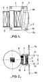
- Fig. 1 is a top view, in partial section, of an ignition coil according to the invention.
- Fig. 2 is a side view of the coil of FIG. 1.
- the ignition coil fig. 1 and 2
- the ignition coil comprises a closed magnetic circuit 1 which, in this embodiment, consists of a plurality of sheets stacked on top of each other.
- a permanent magnet magnetized in the direction of its thickness, is placed in a branch 3 of said circuit 1.
- a primary winding 4 and a secondary winding 5 surround the branch 6 which, in this exemplary embodiment, consists of a fraction of the sheets constituting the half-branch 3a forming, with the half-branch 3b, the branch 3.
- the magnetic flux bypass circuit consists of sheets 7 and 8, of mild steel, spaced apart from each other by a distance E and arranged, by means of insulating plates 9 and 10 of thickness d, on either side of branch 3.
- the sheets 7 and 8, made of mild steel, and the insulating plates 9 and 10 hold the permanent magnet 2 and the portion of the magnetic circuit constituting the branch 3, by means of known assembly means, such as the rivets 11 and 12 for example.
- the sheets 7 and 8 each have an extension 7a and 8a, which extensions are provided with openings (not shown) which secure the ignition coil to the vehicle or to an intermediate support by means of screws for example.
- said attachment can be ensured with a single extension on one of the sheets 7, 8, the other sheet then having the shape of a simple plate.
- the insulating plates 9 and 10 can be constituted by an insulating coating of the sheets 7 and 8.
Description
- La présente invention concerne une bobine d'allumage pour moteur à combustion interne, notamment de véhicules automobiles, bobine d'allumage du type comprenant un circuit magnétique fermé, des enroulements primaire et secondaire, entourant une des branches dudit circuit, et un aimant permanent disposé dans une autre branche, laquelle autre branche est munie d'un circuit de dérivation du flux magnétique créé par l'enroulement primaire.
- De telles bobines travaillant sur une grande partie du cycle d'hystérésis du circuit magnétique apportent une amélioration notable des caractéristiques par rapport aux bobines sans aimant permanent qui n'utilisent que la moitié du cycle.
- La demande de brevet européen No 0034955 décrit, dans un premier mode de réalisation, un circuit magnétique fermé, pour bobine d'allumage, lequel circuit magnétique présente l'inconvénient de nécessiter l'emploi d'un aimant permanent à champ coercitif très élevé pour éviter la désaimantation dudit aimant lors de l'inversion de flux.
- Ce genre d'aimant est coûteux et peu disponible à ce jour, ce qui n'est pas compatible avec une fabrication de grande série. Le deuxième mode de réalisation de la demande précitée remédie à cet inconvénient et prévoit, à cet effet, un circuit magnétique dans lequel un circuit de dérivation comporte un entrefer de grandeur déterminée, lequel entrefer est ménagé à l'une des extrémités de la branche dans laquelle est disposé l'aimant permanent. Mais, dans ces modes de réalisation, les moyens de fixation de la bobine d'allumage, généralement constitués d'une bride munie d'ouvertures pour la fixation sur le véhicule, au moyen de vis prévues à cet effet, ne participent pas magnétiquement aux caractéristiques du circuit magnétique, ce qui n'est pas avantageux en ce qui concerne les économies de matière et de prix de revient.
- La présente invention a pour but de remédier à cet inconvénient et concerne, à cet effet, une bobine d'allumage du type comportant un circuit magnétique fermé, des enroulements primaire et secondaire, entourant une des branches dudit circuit, et un aimant permanent disposé dans une autre branche munie d'un circuit de dérivation du flux magnétique, caractérisée en ce que le circuit de dérivation du flux magnétique est constitué de tôles, en acier doux, disposées de part et d'autre de la branche; en ce que des plaquettes isolantes d'épaisseur d sont intercalées entre ces tôles et cette branche, dans laquelle est disposé l'aimant; en ce que les tôles maintiennent cet aimant permanent et cette branche par des moyens d'assemblage connus, et en ce qu'au moins une des tôles, constituant le circuit de dérivation du flux magnétique, comporte un prolongement muni, au moins, d'une ouverture pour la fixation de ladite bobine sur le véhicule.
- La description qui va suivre en regard des dessins annexés fera mieux comprendre comment l'invention peut être réalisée.
- La fig. 1 est une vue de dessus, en coupe partielle, d'une bobine d'allumage selon l'invention.
- La fig. 2 est une vue de côté de la bobine de la fig. 1.
- Selon un mode de réalisation préféré, la bobine d'allumage, fig. 1 et 2, comporte un circuit magnétique fermé 1 qui, dans cet exemple de réalisation, est constitué d'une pluralité de tôles empilées les unes sur les autres. Un aimant permanent 2, aimanté dans le sens de son épaisseur, est disposé dans une branche 3 dudit circuit 1.
- Un enroulement primaire 4 et un enroulement secondaire 5 entourent la branche 6 qui, dans cet exemple de réalisation, est constituée d'une fraction des tôles constituant la demi-branche 3a formant, avec la demi-branche 3b, la branche 3.
- Conformément à la présente invention, le circuit de dérivation du flux magnétique est constitué de tôles 7 et 8, en acier doux, éloignées l'une de l'autre d'une distance E et disposées, par l'intermédiaire de plaquettes isolantes 9 et 10 d'épaisseur d, de part et d'autre de la branche 3.
- Les tôles 7 et 8, en acier doux, et les plaquettes isolantes 9 et 10 maintiennent l'aimant permanent 2 et la portion du circuit magnétique constituant la branche 3, par l'intermédiaire de moyens d'assemblage connus, tels les rivets 11 et 12 par exemple.
- Dans cet exemple de réalisation, les tôles 7 et 8 comportent chacune un prolongement 7a et 8a, lesquels prolongements sont munis d'ouvertures (non représentées) qui assurent la fixation de la bobine d'allumage sur le véhicule ou sur un support intermédiaire au moyen de vis par exemple.
- Il est évident que, selon le mode de fixation choisi, ladite fixation peut être assurée qu'avec un seul prolongement sur l'une des tôles 7, 8, l'autre tôle ayant alors la forme d'une simple plaquette.
- D'autres modifications peuvent être apportées au mode de réalisation décrit comme, par exemple, en ce que les plaquettes isolantes 9 et 10 peuvent être constituées par un enrobage isolant des tôles 7 et 8.
Claims (1)
- Bobine d'allumage pour moteur à combustion interne, notamment de véhicules automobiles, du type comportant un circuit magnétique fermé (1), des enroulements primaire (4) et secondaire (5), entourant une branche (6) dudit circuit (1 ), et un aimant permanent (2) disposé dans une branche (3) munie d'un circuit de dérivation du flux magnétique, caractérisée en ce que le circuit de dérivation du flux magnétique est constitué de tôles (7 et 8), en acier doux, disposées de part et d'autre de la branche (3); en ce que des plaquettes isolantes (9 et 10) d'épaisseur d sont intercalées entre ces tôles (7 et 8) et cette branche (3), dans laquelle est disposé l'aimant (2); en ce que les tôles (7 et 8) et les plaquettes (9 et 10) maintiennent l'aimant permanent (2) et la branche (3) par des moyens d'assemblage connus (11 et 12), et en ce qu'au moins une des tôles (7, 8) comporte un prolongement (7a, 8a) muni, au moins, d'une ouverture pour la fixation de ladite bobine sur le véhicule.
Applications Claiming Priority (2)
| Application Number | Priority Date | Filing Date | Title |
|---|---|---|---|
| FR8014894A FR2486160A1 (fr) | 1980-07-04 | 1980-07-04 | Perfectionnement aux bobines d'allumage pour moteurs a combustion interne |
| FR8014894 | 1980-07-04 |
Publications (2)
| Publication Number | Publication Date |
|---|---|
| EP0043744A1 EP0043744A1 (fr) | 1982-01-13 |
| EP0043744B1 true EP0043744B1 (fr) | 1984-03-07 |
Family
ID=9243842
Family Applications (1)
| Application Number | Title | Priority Date | Filing Date |
|---|---|---|---|
| EP19810400884 Expired EP0043744B1 (fr) | 1980-07-04 | 1981-06-03 | Bobine d'allumage pour moteur à combustion interne |
Country Status (4)
| Country | Link |
|---|---|
| EP (1) | EP0043744B1 (fr) |
| DE (1) | DE3162497D1 (fr) |
| ES (1) | ES8205039A1 (fr) |
| FR (1) | FR2486160A1 (fr) |
Families Citing this family (3)
| Publication number | Priority date | Publication date | Assignee | Title |
|---|---|---|---|---|
| FR2531751A1 (fr) * | 1982-08-11 | 1984-02-17 | Ducellier & Cie | Bobine d'allumage pour moteur a combustion interne |
| DE3505367A1 (de) * | 1985-02-15 | 1986-08-28 | Daimler-Benz Ag, 7000 Stuttgart | Zuendspule fuer brennkraftmaschinen |
| JP3391049B2 (ja) * | 1993-06-18 | 2003-03-31 | 株式会社デンソー | 点火コイル |
Family Cites Families (3)
| Publication number | Priority date | Publication date | Assignee | Title |
|---|---|---|---|---|
| DE2720065A1 (de) * | 1977-05-05 | 1978-11-09 | Bosch Gmbh Robert | Anordnung von zuendspulen |
| JPS5450733A (en) * | 1977-09-30 | 1979-04-20 | Hitachi Ltd | Ignitor for internal combustion engine |
| IT1101065B (it) * | 1978-11-13 | 1985-09-28 | Magneti Marelli Spa | Bobina d'accensione per autoveicoli |
-
1980
- 1980-07-04 FR FR8014894A patent/FR2486160A1/fr active Granted
-
1981
- 1981-06-03 EP EP19810400884 patent/EP0043744B1/fr not_active Expired
- 1981-06-03 DE DE8181400884T patent/DE3162497D1/de not_active Expired
- 1981-06-30 ES ES503561A patent/ES8205039A1/es not_active Expired
Also Published As
| Publication number | Publication date |
|---|---|
| ES503561A0 (es) | 1982-05-16 |
| DE3162497D1 (en) | 1984-04-12 |
| FR2486160A1 (fr) | 1982-01-08 |
| EP0043744A1 (fr) | 1982-01-13 |
| ES8205039A1 (es) | 1982-05-16 |
| FR2486160B1 (fr) | 1982-12-10 |
Similar Documents
| Publication | Publication Date | Title |
|---|---|---|
| EP0743738B1 (fr) | Alternateur, notamment pour véhicule automobile, comportant un agencement perfectionné de diodes de redressement | |
| FR2537799A1 (fr) | ||
| EP0118454B1 (fr) | Bobine d'allumage pour moteurs a combustion interne | |
| EP1057242B1 (fr) | Machine electrique tournante a aimants permanents et a reluctance possedant une construction perfectionnee | |
| US5214336A (en) | Motor and/or generator in which radially projecting pole shanks are laterally offset at an angle relative to the radial center line of symmetry of a stator sector | |
| EP0945966B1 (fr) | Moteur électrique | |
| EP0043744B1 (fr) | Bobine d'allumage pour moteur à combustion interne | |
| FR2618271A2 (fr) | Rotor a poles a griffes pour un generateur electrique, notamment un alternateur de vehicule automobile. | |
| EP0378596B1 (fr) | Moteur electrique synchrone di- ou polyphase a rotor en forme de disque | |
| FR2791485A1 (fr) | Machine tournante comprenant des moyens d'excitation perfectionnes | |
| EP0034955B1 (fr) | Bobine d'allumage pour moteurs à combustion interne | |
| FR2574880A1 (fr) | Systeme formant butee magnetique axiale pour machine tournante | |
| CH643680A5 (fr) | Electro-aimant pour frein. | |
| GB2088144A (en) | Stepping motor | |
| EP3229348B1 (fr) | Rotor pour machine électrique tournante | |
| EP0072266B1 (fr) | Procédé d'obtention d'une bobine à circuit magnétique fermé et à aimant permanent pour l'allumage de moteurs à combustion | |
| EP0687055B1 (fr) | Perfectionnements aux transmissions de véhicules équipées de ralentisseurs à courants de Foucault, et aux organes de fixation pour de telles transmissions | |
| FR2573586A1 (fr) | Perfectionnements aux moteurs a reluctance variable | |
| FR3082371A1 (fr) | Stator de machine electrique tournante munie d'une confirguration de bobinage optimisee | |
| EP0782240B1 (fr) | Machine électrique tournante avec mise à l'air | |
| FR1465746A (fr) | Perfectionnements aux dispositifs de réduction de vitesse de véhicules | |
| CZ2001999A3 (cs) | Stator elektromotoru s permanentními magnety | |
| FR3072836A1 (fr) | Machine a griffes polaires | |
| JPH0744809B2 (ja) | 小形電動機用界磁装置 | |
| FR3127654A1 (fr) | Corps de stator pour moteur électrique, stator, moteur électrique et procédé de fabrication associé |
Legal Events
| Date | Code | Title | Description |
|---|---|---|---|
| PUAI | Public reference made under article 153(3) epc to a published international application that has entered the european phase |
Free format text: ORIGINAL CODE: 0009012 |
|
| AK | Designated contracting states |
Designated state(s): DE GB IT SE |
|
| 17P | Request for examination filed |
Effective date: 19811204 |
|
| ITF | It: translation for a ep patent filed |
Owner name: SOCIETA' ITALIANA BREVETTI S.P.A. |
|
| GRAA | (expected) grant |
Free format text: ORIGINAL CODE: 0009210 |
|
| AK | Designated contracting states |
Designated state(s): DE GB IT SE |
|
| PG25 | Lapsed in a contracting state [announced via postgrant information from national office to epo] |
Ref country code: SE Free format text: THE PATENT HAS BEEN ANNULLED BY A DECISION OF A NATIONAL AUTHORITY Effective date: 19840307 |
|
| REF | Corresponds to: |
Ref document number: 3162497 Country of ref document: DE Date of ref document: 19840412 |
|
| PLBE | No opposition filed within time limit |
Free format text: ORIGINAL CODE: 0009261 |
|
| STAA | Information on the status of an ep patent application or granted ep patent |
Free format text: STATUS: NO OPPOSITION FILED WITHIN TIME LIMIT |
|
| 26N | No opposition filed | ||
| ITTA | It: last paid annual fee | ||
| PGFP | Annual fee paid to national office [announced via postgrant information from national office to epo] |
Ref country code: GB Payment date: 20000526 Year of fee payment: 20 |
|
| PGFP | Annual fee paid to national office [announced via postgrant information from national office to epo] |
Ref country code: DE Payment date: 20000617 Year of fee payment: 20 |
|
| PG25 | Lapsed in a contracting state [announced via postgrant information from national office to epo] |
Ref country code: GB Free format text: LAPSE BECAUSE OF EXPIRATION OF PROTECTION Effective date: 20010602 |
|
| REG | Reference to a national code |
Ref country code: GB Ref legal event code: PE20 Effective date: 20010602 |