EP0117928B1 - Verfahren zur Erzeugung von Stahl durch Einschmelzen von Eisenschwamm im Lichtbogenofen - Google Patents
Verfahren zur Erzeugung von Stahl durch Einschmelzen von Eisenschwamm im Lichtbogenofen Download PDFInfo
- Publication number
- EP0117928B1 EP0117928B1 EP83201854A EP83201854A EP0117928B1 EP 0117928 B1 EP0117928 B1 EP 0117928B1 EP 83201854 A EP83201854 A EP 83201854A EP 83201854 A EP83201854 A EP 83201854A EP 0117928 B1 EP0117928 B1 EP 0117928B1
- Authority
- EP
- European Patent Office
- Prior art keywords
- furnace
- electric
- process according
- arc furnace
- direct reduction
- Prior art date
- Legal status (The legal status is an assumption and is not a legal conclusion. Google has not performed a legal analysis and makes no representation as to the accuracy of the status listed.)
- Expired
Links
- 238000000034 method Methods 0.000 title claims description 27
- 230000008569 process Effects 0.000 title claims description 24
- 229910000831 Steel Inorganic materials 0.000 title claims description 7
- 239000010959 steel Substances 0.000 title claims description 7
- 238000004519 manufacturing process Methods 0.000 title description 6
- XEEYBQQBJWHFJM-UHFFFAOYSA-N Iron Chemical compound [Fe] XEEYBQQBJWHFJM-UHFFFAOYSA-N 0.000 claims description 92
- 230000009467 reduction Effects 0.000 claims description 63
- 229910052742 iron Inorganic materials 0.000 claims description 46
- 239000007789 gas Substances 0.000 claims description 45
- 229910052799 carbon Inorganic materials 0.000 claims description 31
- OKTJSMMVPCPJKN-UHFFFAOYSA-N Carbon Chemical compound [C] OKTJSMMVPCPJKN-UHFFFAOYSA-N 0.000 claims description 30
- 238000002485 combustion reaction Methods 0.000 claims description 19
- 238000010891 electric arc Methods 0.000 claims description 18
- 239000007787 solid Substances 0.000 claims description 16
- 239000000463 material Substances 0.000 claims description 15
- 239000007788 liquid Substances 0.000 claims description 11
- 239000002184 metal Substances 0.000 claims description 7
- 229910052751 metal Inorganic materials 0.000 claims description 7
- 239000003245 coal Substances 0.000 claims description 6
- 238000002844 melting Methods 0.000 claims description 6
- 230000008018 melting Effects 0.000 claims description 6
- QVGXLLKOCUKJST-UHFFFAOYSA-N atomic oxygen Chemical compound [O] QVGXLLKOCUKJST-UHFFFAOYSA-N 0.000 claims description 5
- 238000002309 gasification Methods 0.000 claims description 5
- 229910052760 oxygen Inorganic materials 0.000 claims description 5
- 239000001301 oxygen Substances 0.000 claims description 5
- 239000000969 carrier Substances 0.000 claims description 4
- 238000001465 metallisation Methods 0.000 claims description 4
- 239000003638 chemical reducing agent Substances 0.000 claims description 3
- 239000002918 waste heat Substances 0.000 claims description 3
- 239000003546 flue gas Substances 0.000 claims 2
- 238000011946 reduction process Methods 0.000 claims 1
- 239000000567 combustion gas Substances 0.000 description 6
- 239000003575 carbonaceous material Substances 0.000 description 5
- 239000005539 carbonized material Substances 0.000 description 3
- 238000003723 Smelting Methods 0.000 description 2
- 230000033228 biological regulation Effects 0.000 description 2
- 238000006243 chemical reaction Methods 0.000 description 2
- 230000007423 decrease Effects 0.000 description 2
- 238000010586 diagram Methods 0.000 description 2
- 239000000428 dust Substances 0.000 description 2
- 238000005265 energy consumption Methods 0.000 description 2
- 238000010438 heat treatment Methods 0.000 description 2
- 230000001105 regulatory effect Effects 0.000 description 2
- 239000002893 slag Substances 0.000 description 2
- 238000003860 storage Methods 0.000 description 2
- 235000019738 Limestone Nutrition 0.000 description 1
- 229910000805 Pig iron Inorganic materials 0.000 description 1
- 238000010795 Steam Flooding Methods 0.000 description 1
- NINIDFKCEFEMDL-UHFFFAOYSA-N Sulfur Chemical compound [S] NINIDFKCEFEMDL-UHFFFAOYSA-N 0.000 description 1
- 238000009825 accumulation Methods 0.000 description 1
- 238000007664 blowing Methods 0.000 description 1
- 150000001721 carbon Chemical class 0.000 description 1
- 230000001419 dependent effect Effects 0.000 description 1
- 238000009826 distribution Methods 0.000 description 1
- 230000000694 effects Effects 0.000 description 1
- 230000005611 electricity Effects 0.000 description 1
- 238000010304 firing Methods 0.000 description 1
- 230000008014 freezing Effects 0.000 description 1
- 238000007710 freezing Methods 0.000 description 1
- 239000003077 lignite Substances 0.000 description 1
- 239000006028 limestone Substances 0.000 description 1
- 238000010309 melting process Methods 0.000 description 1
- 238000013021 overheating Methods 0.000 description 1
- 238000010248 power generation Methods 0.000 description 1
- 230000009257 reactivity Effects 0.000 description 1
- 230000008439 repair process Effects 0.000 description 1
- 238000000926 separation method Methods 0.000 description 1
- 238000007873 sieving Methods 0.000 description 1
- 239000007858 starting material Substances 0.000 description 1
- 229910052717 sulfur Inorganic materials 0.000 description 1
- 239000011593 sulfur Substances 0.000 description 1
Images

Classifications
-
- C—CHEMISTRY; METALLURGY
- C21—METALLURGY OF IRON
- C21C—PROCESSING OF PIG-IRON, e.g. REFINING, MANUFACTURE OF WROUGHT-IRON OR STEEL; TREATMENT IN MOLTEN STATE OF FERROUS ALLOYS
- C21C5/00—Manufacture of carbon-steel, e.g. plain mild steel, medium carbon steel or cast steel or stainless steel
- C21C5/52—Manufacture of steel in electric furnaces
- C21C5/5252—Manufacture of steel in electric furnaces in an electrically heated multi-chamber furnace, a combination of electric furnaces or an electric furnace arranged for associated working with a non electric furnace
-
- C—CHEMISTRY; METALLURGY
- C21—METALLURGY OF IRON
- C21B—MANUFACTURE OF IRON OR STEEL
- C21B13/00—Making spongy iron or liquid steel, by direct processes
- C21B13/12—Making spongy iron or liquid steel, by direct processes in electric furnaces
Definitions
- the invention relates to a method for producing steel by melting sponge iron in an electric arc furnace, the sponge iron being produced by direct reduction.
- the arc furnace operation is also inevitably associated with strongly fluctuating energy consumption due to its characteristic and, moreover, discontinuous mode of operation. These fluctuations extend both to the chronological sequence and to the absolute amount of the decrease in energy.
- An electrical network is required to connect an arc furnace because it is so strong that the reaction - due to furnace operation - does not exceed the maximum permissible limit values.
- the object of the invention is to provide a method which makes it possible to enable the advantageous operation of the arc furnace with sump by ensuring that hot metal is sufficiently available and at the same time that the process sequence is as economical as possible.
- the invention solves this problem in that the sponge iron is reacted on a bath of liquid, carbon-containing iron in the Uchtbogenofen, wherein the liquid, carbon-containing iron (hot metal) is also generated from sponge iron or pre-reduced ore in an electric reduction furnace, which is dependent on the is regulated by the electric arc furnace-induced load fluctuations so that a practically constant load on the electrical network results.
- the process according to the invention thus achieves an overall effect by combining a process step in which the carbon-containing iron required for the sump in the arc furnace is obtained - and preferably from the same starting material as is used in the arc furnace - with the melting of the sponge iron in the arc furnace , which goes beyond the sum of the individual processes taking place in the process sections, because the load on the electrical network is largely evened out in a surprisingly simple manner at the same time as the melting process is improved.
- arc furnace Under the expression arc furnace. are to be understood as directly heated arc furnaces, in which the heating is carried out by electric arcs burning between the electrodes and the metallic insert or the steel bath (direct arc furnace).
- the term “electric reduction furnace” means furnaces in which the electrodes are either immersed in an open slag bath or in a standing Möller column and in which the energy conversion takes place preferably by means of resistance heating (submerged arc furnace). These furnaces are well suited for reduction work, even with an open slag bath. From sponge iron and added carbon carriers, they produce carbon-containing iron, which is used in the arc furnace as a sump.
- the electric reduction furnaces can be operated with variable power consumption.
- the waste heat resulting from the direct reduction in the exhaust gas and the energy carriers occurring during or direct reduction and / or for the direct reduction are used to generate electrical energy to cover the energy requirements of the electric reduction furnace and arc furnace combination.
- Energy sources can be excess solid, carbon-containing materials or combustible gases which are produced in the direct reduction or excess which are produced in the production of the reducing medium for the direct reduction. flammable gases or solid, carbonaceous materials.
- An advantageous embodiment consists in that the amount and the analysis of the carbon-containing iron used as the sump in the arc furnace are selected such that the total carbon balance is balanced during the charging of sponge iron in the arc furnace, the active power of the arc furnace being regulated in such a way that the arc furnace is in the thermal equilibrium necessary for melting iron sponge. Thermal equilibrium means that there is no overheating and no freezing.
- Another advantageous embodiment consists in the fact that sponge iron with a lower degree of metallization is mainly used for the production of liquid, carbon-containing iron (hot metal) in the electric reduction furnace.
- An advantageous embodiment consists in that the excess carbon-containing material separated from the discharge of the direct reduction with solid carbon-containing reducing agents is at least partially burned in a combustion unit with the addition of oxygen-containing gases, the hot combustion gases and the exhaust gas of the direct reduction are used to generate electrical energy, wherein the amount of electrical energy generated is controlled so that this corresponds at least to the maximum energy requirement of the arc furnace plus the minimum energy requirement of the electric reduction furnace, and that the energy not required by the arc furnace is converted in the electric reduction furnace.
- the excess carbonaceous material is completely burned if its quality is not suitable for use in the electric reduction furnace or if an addition is not required there. Good quality means that the ash and sulfur content is relatively low and the ash is basic. It is also possible to process the separated carbonaceous material and then to insert the good quality fraction into the electric reduction furnace and the poor quality fraction into the combustion.
- the minimum energy requirement of the electric reduction furnace is the holding power.
- the sensible heat of the hot combustion gases and the exhaust gases from the direct reduction are used to generate steam, and the steam drives a generator to generate electricity via steam turbines.
- the hot combustion gases and the exhaust gases from the direct reduction are expediently conducted separately into separate steam generators and the steam flows into separate turbines.
- the turbine for the steam of the exhaust gas of the direct reduction can always be operated in the optimal range, and better utilization and control is possible.
- the amount of electrical energy generated must correspond to the maximum energy requirement of the electric arc furnace plus the minimum energy requirement of the electric reduction furnace. More electrical energy can also be generated for other purposes of one's own operation, but this additional generation is then not included in the regulation of the current distribution.
- the electrical energy is distributed in such a way that the energy requirement of the arc furnace is always "met", i.e. if it has high energy requirements, the electric reduction furnace receives less electrical energy, and when the arc furnace is switched off, the electric reduction furnace receives more energy.
- the sponge iron is divided in such a way that the amount of carbon-containing iron (hot metal) required for steel production in the electric arc furnace is obtained in the electric reduction furnace.
- the sponge iron can be used hot in the smelting furnaces.
- the combustion of the excess carbonaceous material can take place in fluidized bed apparatuses or dust fires, such as e.g. B. cyclone firing.
- a preferred embodiment is that the exhaust gas from the direct reduction is afterburned before use in electrical power generation.
- a preferred embodiment is that further combustible material is charged into the combustion unit. As a result, self-sufficient operation can be carried out even when the heat in the exhaust gas and the hot combustion gases of the excess carbonaceous material are too low.
- combustion unit is a circulating fluidized bed.
- the circulating fluidized bed works without a jump in the material density between the dense phase and the dust space above.
- the solids concentration decreases continuously from bottom to top.
- the areas are: or where and are.
- a preferred embodiment consists in that a flammable gas is generated by separate smoldering and / or partial gasification of solid, carbon-containing material, the combustible gas is used to generate electrical energy and the smoldered solid, carbon-containing material in the direct reduction and / or the electroreduction furnace and / or the combustion unit is used. Direct reduction is relieved by the use of carbon-containing material on the exhaust side and its throughput is increased. Since the exhaust gases from the direct reduction contain fewer combustible gaseous components, less electrical energy is generated by the exhaust gas, i. H. the non-controllable base load becomes smaller and the control possibility of the electrical energy generated by the combustion increases.
- Part of the carbonized material, or possibly everything, can be fed into the combustion unit, so that the quantity charged in the direct reduction is also largely flexible.
- the generation of electrical energy by the combustible gases is very flexible. Some of the flammable gas can also be used for other purposes in your own company.
- a preferred embodiment is that the smoldering and / or partial gasification takes place in a circulating fluidized bed.
- the circulating fluidized bed is very suitable and flexible to operate.
- a particularly suitable method is described in EP-A-0 062 363. If the carbonized material from the gasification stage is used in the direct reduction, no charging takes place in the combustion stage.
- a preferred embodiment consists of the fact that combustible gas is stored in a gas storage device and is removed when necessary to generate electrical energy. A very good flexibility is achieved through this storage, and reserves are also created especially for the start-up and shutdown operations.
- a preferred embodiment is that the combustible gas is used to generate electrical energy using a gas turbine.
- a very fast regulation of the amount of energy generated is possible with a gas turbine.
- a preferred embodiment is that baking coals are used in the circulating fluidized bed. This makes it possible to use these coals without additional effort, which cannot be used directly in direct reduction.
- One embodiment consists of the fact that the excess carbon-containing material separated from the discharge of the direct reduction is used in the electric reduction furnace, additional energy sources are burned in a combustion unit with the addition of oxygen-containing gases, the hot combustion gases and the exhaust gas of the direct reduction are used to generate electrical energy , wherein the amount of electrical energy generated is controlled so that it corresponds at least to the maximum energy consumption of the arc furnace plus the minimum energy requirement of the electric reduction furnace, and that the energy not required by the arc furnace is converted in the electric reduction furnace.
- the separated excess carbon is completely added to the electric reduction furnace when this carbon is of good quality and is required in the electric reduction furnace.
- a preferred embodiment is that the direct reduction is carried out in a rotary kiln.
- the coals used as reducing agents mostly contain higher levels of volatile components, such as. B. lignite, and have a high reactivity.
- FIG. 1 shows. is charged into the rotary kiln 1 iron ore 2 and reduced to sponge iron.
- the discharge material 3 is separated in a separation stage 4 into sponge iron 5 and excess carbon-containing material, of which a part 6a is passed into the electric reduction furnace 7 and the other part 6b into the circulating fluidized bed 8 and is burned by means of air 9.
- the hot combustion gas 10 is fed into the steam generator 11.
- a generator 13 is driven with the steam 12.
- the electrical energy generated is fed via line 14 to the electric reduction furnace 7 and the arc furnace 16.
- the exhaust gas 17 of the rotary kiln 1 is afterburned in a post-combustion chamber 18 with the addition of air 19.
- the hot gas 20 is fed into the steam generator 21.
- a generator 23 is driven with the steam 22.
- the electrical energy generated is fed into line 14 via line 24.
- the iron sponge 5 is charged in part 5a in the electric reduction furnace 7 and in part 5b in the arc furnace 16.
- the pig iron produced in the electric reduction furnace 7 is charged into the arc furnace 16, from which the steel 25 is drawn off. As much electrical energy as is required is always supplied to the arc furnace 16 via line 14a. The remaining electrical energy is fed into the electric reduction furnace 7 via line 14b.
- the rotary kiln 1 can be operated with coal with a high proportion of volatile components. which are charged via 26 into the loading end and are partly blown into the discharge end by the blowing device 27.
- the exhaust gas 17 contains higher proportions of combustible gaseous components and the amount of electrical energy generated in 24 is correspondingly large.
- coal 29 can additionally be smelted and partially burnt with gases 30 containing oxygen.
- the combustible gas 31 is burned in a gas turbine 32 that drives a generator 33.
- the electrical energy generated is fed into line 14 via line 34.
- the smoldered carbon-containing material is charged from the fluidized bed 28 via line 35 into the rotary kiln 1. In this case, no coal with a high proportion of volatile components is charged into the rotary kiln and the exhaust gas 17 contains only a small proportion of combustible, gaseous components.
- the amount of electrical energy generated in 24 is correspondingly less.
- the generation of electrical energy can be increased by adding coal 36 to the fluidized bed 8. Part of the carbonized material from the fluidized bed 28 can be fed into the fluidized bed 8 via line 37.
- Flammable gas is stored in the gas store 38 and removed if necessary. Flammable gas can be withdrawn for operation via line 39 if this amount is scheduled for generation.
- the liquid, carbon-containing iron produced in the electric reduction furnace is adjusted in terms of quantity and analysis - mainly carbon - in such a way that the total carbon balance is balanced when the sponge iron is charged. If, e.g. B. by a mistake in sponge iron production, sponge iron of a lower degree of metallization, z. B. instead of 92% only 85%, this can still be processed. However, the spongy iron is only used to charge the electric reduction furnace. It is therefore possible to operate the process with spongy iron with different degrees of metallization.
- the steam generated in the steam generator 11 can also be passed to the steam generator 21 via line 12a.
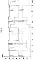
- FIG. 2 shows a typical load diagram for three arc furnaces and two electric reduction furnaces that work in a combined operation.
- the time in minutes is plotted on the x-axis and the active power in megawatts on the y-axis.
- the dotted curve shows the sum of the active powers of the electric reduction furnaces
- the dashed curve shows the sum of the active powers of the arc furnaces
- the solid curve shows the sum of the active powers of all melting furnaces.
- the diagram shows the course of typical work cycles. In particular, it can be seen that the total active power of all furnaces is relatively constant, although the arc furnaces have very large fluctuations in power consumption.
- the advantages of the invention are that the entire smelting process can be carried out independently of the performance of the available public supply network, that the operation takes place with minimal energy requirements per ton of steel, that the waste heat of the direct reduction producing the sponge iron is optimally used and that the excess carbon-containing material is used Material of the discharge of the direct reduction and possibly additionally used coal can be burned in an environmentally friendly manner by adding limestone with the accumulation of a landfillable CaS0 4 -containing residue.
Landscapes
- Engineering & Computer Science (AREA)
- Chemical & Material Sciences (AREA)
- Manufacturing & Machinery (AREA)
- Materials Engineering (AREA)
- Metallurgy (AREA)
- Organic Chemistry (AREA)
- Manufacture Of Iron (AREA)
- Vertical, Hearth, Or Arc Furnaces (AREA)
- Refinement Of Pig-Iron, Manufacture Of Cast Iron, And Steel Manufacture Other Than In Revolving Furnaces (AREA)
- Furnace Details (AREA)
- Waste-Gas Treatment And Other Accessory Devices For Furnaces (AREA)
Applications Claiming Priority (2)
| Application Number | Priority Date | Filing Date | Title |
|---|---|---|---|
| DE3300867 | 1983-01-13 | ||
| DE19833300867 DE3300867A1 (de) | 1983-01-13 | 1983-01-13 | Verfahren zur erzeugung von stahl durch einschmelzen von eisenschwamm im lichtbogenofen |
Publications (2)
| Publication Number | Publication Date |
|---|---|
| EP0117928A1 EP0117928A1 (de) | 1984-09-12 |
| EP0117928B1 true EP0117928B1 (de) | 1986-09-10 |
Family
ID=6188150
Family Applications (1)
| Application Number | Title | Priority Date | Filing Date |
|---|---|---|---|
| EP83201854A Expired EP0117928B1 (de) | 1983-01-13 | 1983-12-29 | Verfahren zur Erzeugung von Stahl durch Einschmelzen von Eisenschwamm im Lichtbogenofen |
Country Status (10)
| Country | Link |
|---|---|
| US (1) | US4490168A (enExample) |
| EP (1) | EP0117928B1 (enExample) |
| JP (1) | JPS59136409A (enExample) |
| AU (1) | AU557005B2 (enExample) |
| BR (1) | BR8400133A (enExample) |
| CA (1) | CA1216754A (enExample) |
| DE (2) | DE3300867A1 (enExample) |
| ES (1) | ES528796A0 (enExample) |
| IN (1) | IN158987B (enExample) |
| ZA (1) | ZA84258B (enExample) |
Cited By (1)
| Publication number | Priority date | Publication date | Assignee | Title |
|---|---|---|---|---|
| DE19933536A1 (de) * | 1998-07-17 | 2000-01-27 | Mitsubishi Heavy Ind Ltd | Verfahren zur Herstellung von Stahl |
Families Citing this family (11)
| Publication number | Priority date | Publication date | Assignee | Title |
|---|---|---|---|---|
| DE3334221A1 (de) * | 1983-08-25 | 1985-03-14 | Mannesmann AG, 4000 Düsseldorf | Verfahren zur erzeugung von fluessigem, kohlenstoffhaltigem eisen aus eisenschwamm |
| US4564388A (en) * | 1984-08-02 | 1986-01-14 | Intersteel Technology, Inc. | Method for continuous steelmaking |
| DE3428782A1 (de) * | 1984-08-04 | 1986-02-13 | Metallgesellschaft Ag, 6000 Frankfurt | Verfahren zur erzeugung von eisenschwamm |
| AT387038B (de) * | 1986-11-25 | 1988-11-25 | Voest Alpine Ag | Verfahren und anlage zur gewinnung von elektrischer energie neben der herstellung von fluessigem roheisen |
| AUPN639995A0 (en) * | 1995-11-03 | 1995-11-30 | Technological Resources Pty Limited | A method and an apparatus for producing metals and metal alloys |
| AUPO276496A0 (en) | 1996-10-07 | 1996-10-31 | Technological Resources Pty Limited | A method and an apparatus for producing metals and metal alloys |
| BE1011186A3 (fr) * | 1997-05-30 | 1999-06-01 | Centre Rech Metallurgique | Procede de production de fonte liquide a partir d'eponge de fer et installation pour sa mise en oeuvre. |
| CN101392307B (zh) * | 2007-12-07 | 2010-11-10 | 江苏沙钢集团有限公司 | 环保节能型电炉直接炼钢方法及其装置 |
| DE102016215637A1 (de) | 2016-08-19 | 2018-02-22 | Robert Bosch Gmbh | Kraftstoffeinspritzdüse |
| LU102322B1 (en) * | 2020-12-17 | 2022-06-21 | Wurth Paul Sa | Green production route for low carbon, low nitrogen steel |
| EP4417713A1 (en) | 2023-02-14 | 2024-08-21 | Oterdoom, Harmen | The novel two-step (semi-)continuous process for clean slag and steel or hot metal |
Family Cites Families (14)
| Publication number | Priority date | Publication date | Assignee | Title |
|---|---|---|---|---|
| BE503611A (enExample) * | ||||
| US2894831A (en) * | 1956-11-28 | 1959-07-14 | Old Bruce Scott | Process of fluidized bed reduction of iron ore followed by electric furnace melting |
| US3224871A (en) * | 1961-02-24 | 1965-12-21 | Elektrokemisk As | Process of preheating ores for reduction in smelting furnace |
| US3206299A (en) * | 1961-10-18 | 1965-09-14 | Independence Foundation | Dense-bed, rotary, kiln process and apparatus for pretreatment of a metallurgical charge |
| DE1508049A1 (de) * | 1966-05-05 | 1969-10-02 | Metallgesellschaft Ag | Verfahren zur Verhuetung oxydischer eisenhaltiger Erze |
| DE2127847A1 (en) * | 1970-06-05 | 1971-12-16 | Gonzalez de,Castejon, Javier , Madrid | Iron smelting - using low-grade ores and coal in low-cost appts |
| DD100017A5 (enExample) * | 1971-11-01 | 1973-09-05 | ||
| US3948641A (en) * | 1972-03-04 | 1976-04-06 | Klockner-Werke Ag | Apparatus for the continuous production of steel from ore |
| US3891427A (en) * | 1972-10-12 | 1975-06-24 | Lectromelt Corp | Method for melting prereduced ore and scrap |
| AT336052B (de) * | 1975-08-08 | 1977-04-12 | Voest Ag | Vorrichtung zur verhuttung von eisenerzen |
| DE2624302C2 (de) * | 1976-05-31 | 1987-04-23 | Metallgesellschaft Ag, 6000 Frankfurt | Verfahren zur Durchführung exothermer Prozesse |
| DE2628972C2 (de) * | 1976-06-28 | 1983-12-01 | Paderwerk Gebr. Benteler, 4794 Schloss Neuhaus | Verfahren zur kontinuierlichen Erzeugung von Stahl |
| DE2841697A1 (de) * | 1978-09-25 | 1980-04-10 | Mannesmann Ag | Verfahren zur herstellung von stahl aus eisenschwamm in elektrischen oefen |
| DE3113993A1 (de) * | 1981-04-07 | 1982-11-11 | Metallgesellschaft Ag, 6000 Frankfurt | Verfahren zur gleichzeitigen erzeugung von brenngas und prozesswaerme aus kohlenstoffhaltigen materialien |
-
1983
- 1983-01-13 DE DE19833300867 patent/DE3300867A1/de not_active Withdrawn
- 1983-03-25 IN IN358/CAL/83A patent/IN158987B/en unknown
- 1983-12-29 DE DE8383201854T patent/DE3366151D1/de not_active Expired
- 1983-12-29 EP EP83201854A patent/EP0117928B1/de not_active Expired
-
1984
- 1984-01-10 CA CA000444999A patent/CA1216754A/en not_active Expired
- 1984-01-11 US US06/569,710 patent/US4490168A/en not_active Expired - Fee Related
- 1984-01-11 ES ES528796A patent/ES528796A0/es active Granted
- 1984-01-12 ZA ZA84258A patent/ZA84258B/xx unknown
- 1984-01-12 AU AU23252/84A patent/AU557005B2/en not_active Ceased
- 1984-01-12 BR BR8400133A patent/BR8400133A/pt not_active IP Right Cessation
- 1984-01-13 JP JP59005508A patent/JPS59136409A/ja active Granted
Cited By (2)
| Publication number | Priority date | Publication date | Assignee | Title |
|---|---|---|---|---|
| DE19933536A1 (de) * | 1998-07-17 | 2000-01-27 | Mitsubishi Heavy Ind Ltd | Verfahren zur Herstellung von Stahl |
| DE19933536C2 (de) * | 1998-07-17 | 2002-05-16 | Mitsubishi Heavy Ind Ltd | Verfahren zur Herstellung von Stahl |
Also Published As
| Publication number | Publication date |
|---|---|
| JPS59136409A (ja) | 1984-08-06 |
| EP0117928A1 (de) | 1984-09-12 |
| DE3366151D1 (en) | 1986-10-16 |
| DE3300867A1 (de) | 1984-07-19 |
| AU557005B2 (en) | 1986-11-27 |
| US4490168A (en) | 1984-12-25 |
| BR8400133A (pt) | 1984-08-21 |
| CA1216754A (en) | 1987-01-20 |
| IN158987B (enExample) | 1987-02-28 |
| ZA84258B (en) | 1985-08-28 |
| ES8407102A1 (es) | 1984-08-16 |
| AU2325284A (en) | 1984-07-19 |
| ES528796A0 (es) | 1984-08-16 |
| JPH0373602B2 (enExample) | 1991-11-22 |
Similar Documents
| Publication | Publication Date | Title |
|---|---|---|
| EP0117928B1 (de) | Verfahren zur Erzeugung von Stahl durch Einschmelzen von Eisenschwamm im Lichtbogenofen | |
| EP2297365B1 (de) | Verfahren und system zur energieoptimierten eisenherstellung mit optimiertem co2-ausstoss | |
| EP0139310B1 (de) | Verfahren zur Erzeugung von flüssigem, kohlenstoffhaltigem Eisen aus Eisenschwamm | |
| DE69318750T2 (de) | Schmelzreduktionsverfahren mit hoher Produktivität | |
| EP0171097B1 (de) | Verfahren zur Erzeugung von Eisenschwamm | |
| DE3338478A1 (de) | Verfahren zur abfallbeseitigung | |
| EP2751294A1 (de) | Verfahren zur aufbereitung von abgasen aus anlagen zur roheisenherstellung und/oder von synthesegas | |
| WO2022090390A1 (de) | Stahlherstellung aus eisenschmelze | |
| EP4396383A1 (de) | Verfahren zur herstellung einer eisenschmelze | |
| DE102015202683A1 (de) | Verfahren zum Betreiben eines mit fossilen Brennstoffen betriebenen Kraftwerkes und Kraftwerk zur Verbrennung fossiler Brennstoffe | |
| DE4004938C2 (enExample) | ||
| DE3345107A1 (de) | Verfahren zum schmelzen von zumindest teilweise reduziertem eisenerz | |
| EP1285096A1 (de) | Verfahren und vorrichtung zur herstellung von roheisen oder flüssigen stahlvorprodukten aus eisenerzhältigen einsatzstoffen | |
| WO2023030944A1 (de) | Verfahren zur herstellung einer eisenschmelze | |
| EP0117318B1 (de) | Verfahren zum kontinuierlichen Einschmelzen von Eisenschwamm | |
| DE3320669C3 (de) | Verfahren und Vorrichtung zum Erzeugen eines Reduktionsgases | |
| DE2628972A1 (de) | Verfahren zur kontinuierlichen erzeugung von stahl | |
| CA1081464A (en) | Method for generating gases for the reduction of oxide ores, particularly iron ores | |
| DE69624819T2 (de) | Verfahren zur direkten gewinning von eisen und stahl | |
| DE864000C (de) | Verfahren zur Behandlung von Brennstoff-Erz-Gemischen | |
| DE2535541A1 (de) | Aggregat und verfahren zur gewinnung von gelbem phosphor | |
| DE262968C (enExample) | ||
| DD223728A5 (de) | Verfahren zur reduktion oxidischer eisenerze im drehrohrofen | |
| DE2127847A1 (en) | Iron smelting - using low-grade ores and coal in low-cost appts | |
| JPH06212218A (ja) | 高炉操業方法 |
Legal Events
| Date | Code | Title | Description |
|---|---|---|---|
| PUAI | Public reference made under article 153(3) epc to a published international application that has entered the european phase |
Free format text: ORIGINAL CODE: 0009012 |
|
| AK | Designated contracting states |
Designated state(s): DE FR GB IT |
|
| 17P | Request for examination filed |
Effective date: 19841031 |
|
| GRAA | (expected) grant |
Free format text: ORIGINAL CODE: 0009210 |
|
| AK | Designated contracting states |
Kind code of ref document: B1 Designated state(s): DE FR GB IT |
|
| REF | Corresponds to: |
Ref document number: 3366151 Country of ref document: DE Date of ref document: 19861016 |
|
| ET | Fr: translation filed | ||
| ITF | It: translation for a ep patent filed | ||
| PLBE | No opposition filed within time limit |
Free format text: ORIGINAL CODE: 0009261 |
|
| STAA | Information on the status of an ep patent application or granted ep patent |
Free format text: STATUS: NO OPPOSITION FILED WITHIN TIME LIMIT |
|
| 26N | No opposition filed | ||
| PGFP | Annual fee paid to national office [announced via postgrant information from national office to epo] |
Ref country code: FR Payment date: 19910917 Year of fee payment: 9 |
|
| PGFP | Annual fee paid to national office [announced via postgrant information from national office to epo] |
Ref country code: GB Payment date: 19911224 Year of fee payment: 9 |
|
| ITTA | It: last paid annual fee | ||
| PGFP | Annual fee paid to national office [announced via postgrant information from national office to epo] |
Ref country code: DE Payment date: 19920113 Year of fee payment: 9 |
|
| PG25 | Lapsed in a contracting state [announced via postgrant information from national office to epo] |
Ref country code: GB Effective date: 19921229 |
|
| GBPC | Gb: european patent ceased through non-payment of renewal fee |
Effective date: 19921229 |
|
| PG25 | Lapsed in a contracting state [announced via postgrant information from national office to epo] |
Ref country code: FR Effective date: 19930831 |
|
| PG25 | Lapsed in a contracting state [announced via postgrant information from national office to epo] |
Ref country code: DE Effective date: 19930901 |
|
| REG | Reference to a national code |
Ref country code: FR Ref legal event code: ST |