EP0117928B1 - Process for production of steel by the melt-down of iron-sponge in an electric-arc-furnace - Google Patents
Process for production of steel by the melt-down of iron-sponge in an electric-arc-furnace Download PDFInfo
- Publication number
- EP0117928B1 EP0117928B1 EP83201854A EP83201854A EP0117928B1 EP 0117928 B1 EP0117928 B1 EP 0117928B1 EP 83201854 A EP83201854 A EP 83201854A EP 83201854 A EP83201854 A EP 83201854A EP 0117928 B1 EP0117928 B1 EP 0117928B1
- Authority
- EP
- European Patent Office
- Prior art keywords
- furnace
- electric
- process according
- arc furnace
- direct reduction
- Prior art date
- Legal status (The legal status is an assumption and is not a legal conclusion. Google has not performed a legal analysis and makes no representation as to the accuracy of the status listed.)
- Expired
Links
Images

Classifications
-
- C—CHEMISTRY; METALLURGY
- C21—METALLURGY OF IRON
- C21C—PROCESSING OF PIG-IRON, e.g. REFINING, MANUFACTURE OF WROUGHT-IRON OR STEEL; TREATMENT IN MOLTEN STATE OF FERROUS ALLOYS
- C21C5/00—Manufacture of carbon-steel, e.g. plain mild steel, medium carbon steel or cast steel or stainless steel
- C21C5/52—Manufacture of steel in electric furnaces
- C21C5/5252—Manufacture of steel in electric furnaces in an electrically heated multi-chamber furnace, a combination of electric furnaces or an electric furnace arranged for associated working with a non electric furnace
-
- C—CHEMISTRY; METALLURGY
- C21—METALLURGY OF IRON
- C21B—MANUFACTURE OF IRON OR STEEL
- C21B13/00—Making spongy iron or liquid steel, by direct processes
- C21B13/12—Making spongy iron or liquid steel, by direct processes in electric furnaces
Definitions
- the invention relates to a method for producing steel by melting sponge iron in an electric arc furnace, the sponge iron being produced by direct reduction.
- the arc furnace operation is also inevitably associated with strongly fluctuating energy consumption due to its characteristic and, moreover, discontinuous mode of operation. These fluctuations extend both to the chronological sequence and to the absolute amount of the decrease in energy.
- An electrical network is required to connect an arc furnace because it is so strong that the reaction - due to furnace operation - does not exceed the maximum permissible limit values.
- the object of the invention is to provide a method which makes it possible to enable the advantageous operation of the arc furnace with sump by ensuring that hot metal is sufficiently available and at the same time that the process sequence is as economical as possible.
- the invention solves this problem in that the sponge iron is reacted on a bath of liquid, carbon-containing iron in the Uchtbogenofen, wherein the liquid, carbon-containing iron (hot metal) is also generated from sponge iron or pre-reduced ore in an electric reduction furnace, which is dependent on the is regulated by the electric arc furnace-induced load fluctuations so that a practically constant load on the electrical network results.
- the process according to the invention thus achieves an overall effect by combining a process step in which the carbon-containing iron required for the sump in the arc furnace is obtained - and preferably from the same starting material as is used in the arc furnace - with the melting of the sponge iron in the arc furnace , which goes beyond the sum of the individual processes taking place in the process sections, because the load on the electrical network is largely evened out in a surprisingly simple manner at the same time as the melting process is improved.
- arc furnace Under the expression arc furnace. are to be understood as directly heated arc furnaces, in which the heating is carried out by electric arcs burning between the electrodes and the metallic insert or the steel bath (direct arc furnace).
- the term “electric reduction furnace” means furnaces in which the electrodes are either immersed in an open slag bath or in a standing Möller column and in which the energy conversion takes place preferably by means of resistance heating (submerged arc furnace). These furnaces are well suited for reduction work, even with an open slag bath. From sponge iron and added carbon carriers, they produce carbon-containing iron, which is used in the arc furnace as a sump.
- the electric reduction furnaces can be operated with variable power consumption.
- the waste heat resulting from the direct reduction in the exhaust gas and the energy carriers occurring during or direct reduction and / or for the direct reduction are used to generate electrical energy to cover the energy requirements of the electric reduction furnace and arc furnace combination.
- Energy sources can be excess solid, carbon-containing materials or combustible gases which are produced in the direct reduction or excess which are produced in the production of the reducing medium for the direct reduction. flammable gases or solid, carbonaceous materials.
- An advantageous embodiment consists in that the amount and the analysis of the carbon-containing iron used as the sump in the arc furnace are selected such that the total carbon balance is balanced during the charging of sponge iron in the arc furnace, the active power of the arc furnace being regulated in such a way that the arc furnace is in the thermal equilibrium necessary for melting iron sponge. Thermal equilibrium means that there is no overheating and no freezing.
- Another advantageous embodiment consists in the fact that sponge iron with a lower degree of metallization is mainly used for the production of liquid, carbon-containing iron (hot metal) in the electric reduction furnace.
- An advantageous embodiment consists in that the excess carbon-containing material separated from the discharge of the direct reduction with solid carbon-containing reducing agents is at least partially burned in a combustion unit with the addition of oxygen-containing gases, the hot combustion gases and the exhaust gas of the direct reduction are used to generate electrical energy, wherein the amount of electrical energy generated is controlled so that this corresponds at least to the maximum energy requirement of the arc furnace plus the minimum energy requirement of the electric reduction furnace, and that the energy not required by the arc furnace is converted in the electric reduction furnace.
- the excess carbonaceous material is completely burned if its quality is not suitable for use in the electric reduction furnace or if an addition is not required there. Good quality means that the ash and sulfur content is relatively low and the ash is basic. It is also possible to process the separated carbonaceous material and then to insert the good quality fraction into the electric reduction furnace and the poor quality fraction into the combustion.
- the minimum energy requirement of the electric reduction furnace is the holding power.
- the sensible heat of the hot combustion gases and the exhaust gases from the direct reduction are used to generate steam, and the steam drives a generator to generate electricity via steam turbines.
- the hot combustion gases and the exhaust gases from the direct reduction are expediently conducted separately into separate steam generators and the steam flows into separate turbines.
- the turbine for the steam of the exhaust gas of the direct reduction can always be operated in the optimal range, and better utilization and control is possible.
- the amount of electrical energy generated must correspond to the maximum energy requirement of the electric arc furnace plus the minimum energy requirement of the electric reduction furnace. More electrical energy can also be generated for other purposes of one's own operation, but this additional generation is then not included in the regulation of the current distribution.
- the electrical energy is distributed in such a way that the energy requirement of the arc furnace is always "met", i.e. if it has high energy requirements, the electric reduction furnace receives less electrical energy, and when the arc furnace is switched off, the electric reduction furnace receives more energy.
- the sponge iron is divided in such a way that the amount of carbon-containing iron (hot metal) required for steel production in the electric arc furnace is obtained in the electric reduction furnace.
- the sponge iron can be used hot in the smelting furnaces.
- the combustion of the excess carbonaceous material can take place in fluidized bed apparatuses or dust fires, such as e.g. B. cyclone firing.
- a preferred embodiment is that the exhaust gas from the direct reduction is afterburned before use in electrical power generation.
- a preferred embodiment is that further combustible material is charged into the combustion unit. As a result, self-sufficient operation can be carried out even when the heat in the exhaust gas and the hot combustion gases of the excess carbonaceous material are too low.
- combustion unit is a circulating fluidized bed.
- the circulating fluidized bed works without a jump in the material density between the dense phase and the dust space above.
- the solids concentration decreases continuously from bottom to top.
- the areas are: or where and are.
- a preferred embodiment consists in that a flammable gas is generated by separate smoldering and / or partial gasification of solid, carbon-containing material, the combustible gas is used to generate electrical energy and the smoldered solid, carbon-containing material in the direct reduction and / or the electroreduction furnace and / or the combustion unit is used. Direct reduction is relieved by the use of carbon-containing material on the exhaust side and its throughput is increased. Since the exhaust gases from the direct reduction contain fewer combustible gaseous components, less electrical energy is generated by the exhaust gas, i. H. the non-controllable base load becomes smaller and the control possibility of the electrical energy generated by the combustion increases.
- Part of the carbonized material, or possibly everything, can be fed into the combustion unit, so that the quantity charged in the direct reduction is also largely flexible.
- the generation of electrical energy by the combustible gases is very flexible. Some of the flammable gas can also be used for other purposes in your own company.
- a preferred embodiment is that the smoldering and / or partial gasification takes place in a circulating fluidized bed.
- the circulating fluidized bed is very suitable and flexible to operate.
- a particularly suitable method is described in EP-A-0 062 363. If the carbonized material from the gasification stage is used in the direct reduction, no charging takes place in the combustion stage.
- a preferred embodiment consists of the fact that combustible gas is stored in a gas storage device and is removed when necessary to generate electrical energy. A very good flexibility is achieved through this storage, and reserves are also created especially for the start-up and shutdown operations.
- a preferred embodiment is that the combustible gas is used to generate electrical energy using a gas turbine.
- a very fast regulation of the amount of energy generated is possible with a gas turbine.
- a preferred embodiment is that baking coals are used in the circulating fluidized bed. This makes it possible to use these coals without additional effort, which cannot be used directly in direct reduction.
- One embodiment consists of the fact that the excess carbon-containing material separated from the discharge of the direct reduction is used in the electric reduction furnace, additional energy sources are burned in a combustion unit with the addition of oxygen-containing gases, the hot combustion gases and the exhaust gas of the direct reduction are used to generate electrical energy , wherein the amount of electrical energy generated is controlled so that it corresponds at least to the maximum energy consumption of the arc furnace plus the minimum energy requirement of the electric reduction furnace, and that the energy not required by the arc furnace is converted in the electric reduction furnace.
- the separated excess carbon is completely added to the electric reduction furnace when this carbon is of good quality and is required in the electric reduction furnace.
- a preferred embodiment is that the direct reduction is carried out in a rotary kiln.
- the coals used as reducing agents mostly contain higher levels of volatile components, such as. B. lignite, and have a high reactivity.
- FIG. 1 shows. is charged into the rotary kiln 1 iron ore 2 and reduced to sponge iron.
- the discharge material 3 is separated in a separation stage 4 into sponge iron 5 and excess carbon-containing material, of which a part 6a is passed into the electric reduction furnace 7 and the other part 6b into the circulating fluidized bed 8 and is burned by means of air 9.
- the hot combustion gas 10 is fed into the steam generator 11.
- a generator 13 is driven with the steam 12.
- the electrical energy generated is fed via line 14 to the electric reduction furnace 7 and the arc furnace 16.
- the exhaust gas 17 of the rotary kiln 1 is afterburned in a post-combustion chamber 18 with the addition of air 19.
- the hot gas 20 is fed into the steam generator 21.
- a generator 23 is driven with the steam 22.
- the electrical energy generated is fed into line 14 via line 24.
- the iron sponge 5 is charged in part 5a in the electric reduction furnace 7 and in part 5b in the arc furnace 16.
- the pig iron produced in the electric reduction furnace 7 is charged into the arc furnace 16, from which the steel 25 is drawn off. As much electrical energy as is required is always supplied to the arc furnace 16 via line 14a. The remaining electrical energy is fed into the electric reduction furnace 7 via line 14b.
- the rotary kiln 1 can be operated with coal with a high proportion of volatile components. which are charged via 26 into the loading end and are partly blown into the discharge end by the blowing device 27.
- the exhaust gas 17 contains higher proportions of combustible gaseous components and the amount of electrical energy generated in 24 is correspondingly large.
- coal 29 can additionally be smelted and partially burnt with gases 30 containing oxygen.
- the combustible gas 31 is burned in a gas turbine 32 that drives a generator 33.
- the electrical energy generated is fed into line 14 via line 34.
- the smoldered carbon-containing material is charged from the fluidized bed 28 via line 35 into the rotary kiln 1. In this case, no coal with a high proportion of volatile components is charged into the rotary kiln and the exhaust gas 17 contains only a small proportion of combustible, gaseous components.
- the amount of electrical energy generated in 24 is correspondingly less.
- the generation of electrical energy can be increased by adding coal 36 to the fluidized bed 8. Part of the carbonized material from the fluidized bed 28 can be fed into the fluidized bed 8 via line 37.
- Flammable gas is stored in the gas store 38 and removed if necessary. Flammable gas can be withdrawn for operation via line 39 if this amount is scheduled for generation.
- the liquid, carbon-containing iron produced in the electric reduction furnace is adjusted in terms of quantity and analysis - mainly carbon - in such a way that the total carbon balance is balanced when the sponge iron is charged. If, e.g. B. by a mistake in sponge iron production, sponge iron of a lower degree of metallization, z. B. instead of 92% only 85%, this can still be processed. However, the spongy iron is only used to charge the electric reduction furnace. It is therefore possible to operate the process with spongy iron with different degrees of metallization.
- the steam generated in the steam generator 11 can also be passed to the steam generator 21 via line 12a.
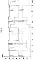
- FIG. 2 shows a typical load diagram for three arc furnaces and two electric reduction furnaces that work in a combined operation.
- the time in minutes is plotted on the x-axis and the active power in megawatts on the y-axis.
- the dotted curve shows the sum of the active powers of the electric reduction furnaces
- the dashed curve shows the sum of the active powers of the arc furnaces
- the solid curve shows the sum of the active powers of all melting furnaces.
- the diagram shows the course of typical work cycles. In particular, it can be seen that the total active power of all furnaces is relatively constant, although the arc furnaces have very large fluctuations in power consumption.
- the advantages of the invention are that the entire smelting process can be carried out independently of the performance of the available public supply network, that the operation takes place with minimal energy requirements per ton of steel, that the waste heat of the direct reduction producing the sponge iron is optimally used and that the excess carbon-containing material is used Material of the discharge of the direct reduction and possibly additionally used coal can be burned in an environmentally friendly manner by adding limestone with the accumulation of a landfillable CaS0 4 -containing residue.
Landscapes
- Engineering & Computer Science (AREA)
- Chemical & Material Sciences (AREA)
- Manufacturing & Machinery (AREA)
- Materials Engineering (AREA)
- Metallurgy (AREA)
- Organic Chemistry (AREA)
- Vertical, Hearth, Or Arc Furnaces (AREA)
- Manufacture Of Iron (AREA)
- Refinement Of Pig-Iron, Manufacture Of Cast Iron, And Steel Manufacture Other Than In Revolving Furnaces (AREA)
- Furnace Details (AREA)
- Waste-Gas Treatment And Other Accessory Devices For Furnaces (AREA)
Description
Die Erfindung betrifft ein Verfahren zur Erzeugung von Stahl durch Einschmelzen von Eisenschwamm im Lichtbogenofen, wobei der Eisenschwamm durch Direktreduktion erzeugt wird.The invention relates to a method for producing steel by melting sponge iron in an electric arc furnace, the sponge iron being produced by direct reduction.
Bekanntlich ergeben sich Schwierigkeiten, wenn ein Lichtbogenofen ausschließlich mit Eisenschwamm beschickt wird. Dies beruht auf der geringen Dichte und schlechten Leitfähigkeit des Eisenschwamms. Dennoch wird angestrebt, im Lichtbogenofen überwiegend Eisenschwamm einzusetzen. Hier ist es vorteilhaft, die sogenannte Sumpf-Fahrweise anzuwenden, die darin besteht, daß der Eisenschwamm auf bereits im Ofen befindliches flüssiges, Kohlenstoffhaltiges Eisen (hot metal) chargiert wird, wobei die weitere Energiezufuhr im wesentlichen über das flüssige Bad erfolgt.As is well known, difficulties arise when an electric arc furnace is only loaded with sponge iron. This is due to the low density and poor conductivity of the sponge iron. Nevertheless, the aim is to use mainly sponge iron in the arc furnace. Here it is advantageous to use the so-called swamp mode of operation, which consists in charging the sponge iron onto liquid, carbon-containing iron (hot metal) already in the furnace, the further supply of energy taking place essentially via the liquid bath.
Bei der Sumpf-Fahrweise muß aber dennoch der Lichtbogenofen alle zwei bis drei Chargen vollständig entleert werden, um die Zustellung auszubessern. Auf diese Weise ist kein unterbrechungsloser Ofenbetrieb mit Sumpf möglich ; vielmehr muß nach dem jeweiligen Entleeren wieder ein Sumpf erzeugt werden, so daß die Vorteile dieser Betriebsweise nur unvollkommen genutzt werden können, wenn kein flüssiges Eisen aus anderer Quelle, vorzugsweise dem Hochofen, zur Verfügung steht. Gerade dieser ist aber in einem Eisenschwamm verarbeitenden Betrieb nicht vorhanden.In the swamp mode of operation, however, the arc furnace must still be completely emptied every two to three batches in order to repair the delivery. In this way, uninterrupted furnace operation with sump is not possible; rather, a sump must be generated again after each emptying, so that the advantages of this mode of operation can only be used incompletely if no liquid iron from another source, preferably the blast furnace, is available. However, it is precisely this that is not available in a sponge processing company.
Der Lichtbogenofenbetrieb ist außerdem aufgrund seiner charakteristischen und und darüber hinaus diskontinuierlichen Arbeitsweise zwangsläufig mit stark schwankender Energieabnahme verbunden. Diese Schwankungen erstrecken sich sowohl auf den zeitlichen Ablauf als auch auf die absolute Höhe der Energieabnahme. Für den Anschluß eines Lichtbogenofens ist ein elektrisches Netz erforderlich, da so stark ist, daß die Rückwirkung - durch den Ofenbetrieb bedingt - die maximal zulässigen Grenzwerte nicht überschreitet.The arc furnace operation is also inevitably associated with strongly fluctuating energy consumption due to its characteristic and, moreover, discontinuous mode of operation. These fluctuations extend both to the chronological sequence and to the absolute amount of the decrease in energy. An electrical network is required to connect an arc furnace because it is so strong that the reaction - due to furnace operation - does not exceed the maximum permissible limit values.
Aufgabe der Erfindung ist es, ein Verfahren zu schaffen, das es erlaubt, die vorteilhafte Betriebsweise des Lichtbogenofens mit Sumpf dadurch zu ermöglichen, daß man für die ausreichende Verfügbarkeit von sogenanntem « hot metal und dabei gleichzeitig für eine größtmögliche Wirtschaftlichkeit des Verfahrensablaufs sorgt.The object of the invention is to provide a method which makes it possible to enable the advantageous operation of the arc furnace with sump by ensuring that hot metal is sufficiently available and at the same time that the process sequence is as economical as possible.
Diese Aufgabe löst die Erfindung dadurch, daß der Eisenschwamm auf einem Bad aus flüssigem, kohlenstoffhaltigem Eisen im Uchtbogenofen umgesetzt wird, wobei das flüssige, kohlenstoffhaltige Eisen (hot metal) ebenfalls aus Eisenschwamm oder vorreduziertem Erz in einem Elektroreduktionsofen erzeugt wird, der in Abhängigkeit von den durch den Lichtbogenofen bedingten elektrischen Lastaufnahme-Schwankungen so geregelt wird, daß eine praktisch gleichbbleibende Belastung des elektrischen Netzes resultiert.The invention solves this problem in that the sponge iron is reacted on a bath of liquid, carbon-containing iron in the Uchtbogenofen, wherein the liquid, carbon-containing iron (hot metal) is also generated from sponge iron or pre-reduced ore in an electric reduction furnace, which is dependent on the is regulated by the electric arc furnace-induced load fluctuations so that a practically constant load on the electrical network results.
Das erfindungsgemäße Verfahren erzielt somit durch die Kombination einer Verfahrensstufe, in der das für den Sumpf im Lichtbogenofen erforderliche kohlenstoffhaltige Eisen gewonnen wird - und zwar vorzugsweise aus dem gleichen Vormaterial, wie es auch im Lichtbogenofen verwendet wird - mit dem Erschmelzen des Eisenschwamms im Lichtbogenofen eine Gesamtwirkung, die über die Summe der in den Verfahrensabschnitten ablaufenden Einzelvorgänge hinausgeht, weil auf überraschend einfache Weise gleichzeitig mit der Verbesserung des Einschmelzvorganges die Belastung des elektrischen Netzes weitgehend vergleichmäßigt wird.The process according to the invention thus achieves an overall effect by combining a process step in which the carbon-containing iron required for the sump in the arc furnace is obtained - and preferably from the same starting material as is used in the arc furnace - with the melting of the sponge iron in the arc furnace , which goes beyond the sum of the individual processes taking place in the process sections, because the load on the electrical network is largely evened out in a surprisingly simple manner at the same time as the melting process is improved.
Unter dem Ausdruck Lichtbogenofen . sind direktbeheizte Lichtbogenöfen zu verstehen, bei denen die Beheizung durch zwischen den Elektroden und dem metallischen Einsatz bzw. dem Stahlbad brennende elektrische Lichtbögen erfolgt (direct arc furnace). Unter dem Ausdruck « Elektroreduktionsofen sind Öfen zu verstehen, bei denen die Elektroden entweder in ein offenes Schlackenbad oder in eine stehende Möller-Säule eintauchen und in denen der Energieumsatz vorzugsweise durch Widerstandserwärmung erfolgt (submerged arc furnace). Diese Öfen sind für Reduktionsarbeit, auch mit offenem Schlackenbad, gut geeignet. Sie erzeugen aus Eisenschwamm und zugesetzten Kohlenstoffträgern Kohlenstoffhaltiges Eisen, das in den Lichtbogenofen als Sumpf eingesetzt wird. Die Elektroreduktionsöfen können mit variabler Leistungsaufnahme betrieben werden.Under the expression arc furnace. are to be understood as directly heated arc furnaces, in which the heating is carried out by electric arcs burning between the electrodes and the metallic insert or the steel bath (direct arc furnace). The term “electric reduction furnace” means furnaces in which the electrodes are either immersed in an open slag bath or in a standing Möller column and in which the energy conversion takes place preferably by means of resistance heating (submerged arc furnace). These furnaces are well suited for reduction work, even with an open slag bath. From sponge iron and added carbon carriers, they produce carbon-containing iron, which is used in the arc furnace as a sump. The electric reduction furnaces can be operated with variable power consumption.
In vorteilhafter weiterer Ausgestaltung der Erfindung wird vorgeschlagen, daß die bei der Direktreduktion im Abgas anfallende Abwärme sowie die bei oder Direktreduktion und/oder für die Direktreduktion anfallenden Energieträger zur Erzeugung von elektrischer Energie zur Deckung des Energiebedarfs des Elektroreduktionsofen- und Lichtbogenofen-Verbundes verwendet werden. Energieträger können bei der Direktreduktion anfallende überschüssige feste, kohlenstoffhaltige Materialien oder brennbare Gase oder bei der Herstellung des reduzierenden Mediums für die Direktreduktion anfallende überschüssige. brennbare Gase oder feste, kohlenstoffhaltige Materialien sein.In an advantageous further embodiment of the invention, it is proposed that the waste heat resulting from the direct reduction in the exhaust gas and the energy carriers occurring during or direct reduction and / or for the direct reduction are used to generate electrical energy to cover the energy requirements of the electric reduction furnace and arc furnace combination. Energy sources can be excess solid, carbon-containing materials or combustible gases which are produced in the direct reduction or excess which are produced in the production of the reducing medium for the direct reduction. flammable gases or solid, carbonaceous materials.
Eine vorteilhafte Ausgestaltung besteht darin, daß die Menge und die Analyse des in den Lichtbogenofen als Sumpf eingesetzten kohlenstoffhaltigen Eisens so gewählt wird, daß während des Chargierens von Eisenschwamm in den Lichtbogenofen die Gesamtkohlenstoffbilanz ausgeglichen wird, wobei die Wirkleistung des Lichtbogenofens so geregelt wird, daß sich der Lichtbogenofen im für das Einschmelzen von Eisenschwamm notwendigen thermischen Gleichgewicht befindet. Thermisches Gleichgewicht bedeutet, daß keine Überhitzung und kein Einfrieren erfolgt.An advantageous embodiment consists in that the amount and the analysis of the carbon-containing iron used as the sump in the arc furnace are selected such that the total carbon balance is balanced during the charging of sponge iron in the arc furnace, the active power of the arc furnace being regulated in such a way that the arc furnace is in the thermal equilibrium necessary for melting iron sponge. Thermal equilibrium means that there is no overheating and no freezing.
Eine weitere vorteilhafte Ausgestaltung besteht darin, daß Eisenschwamm mit geringerem Metallisationsgrad überwiegend zur Herstellung von flüssigem, kohlenstoffhaltigem Eisen (hot metal) im Elektroreduktionsofen verwendet wird.Another advantageous embodiment consists in the fact that sponge iron with a lower degree of metallization is mainly used for the production of liquid, carbon-containing iron (hot metal) in the electric reduction furnace.
Eine vorteilhafte Ausgestaltung besteht darin, daß das aus dem Austrag der Direktreduktion mit festen kohlenstoffhaltigen Reduktionsmitteln abgetrennte überschüssige kohlenstoffhaltige Material mindestens teilweise in einem Verbrennungsaggregat unter Zusatz von sauerstoffhaitigen Gasen verbrannt wird, die heißen Verbrennungsgase und das Abgas der Direktreduktion zur Erzeugung von elektrischer Energie verwendet werden, wobei die Menge der erzeugten elektrischen Energie so geregelt wird, daß diese mindestens dem maximalen Energiebedarf des Lichtbogenofens zuzüglich dem minimalen Energiebedarf des Elektroreduktionsofens entspricht, und daß die vom Lichtbogenofen jeweils nicht benötigte Energie im Elektroreduktionsofen umgesetzt wird. Das überschüssige kohlenstoffhaltige Material wird ganz-verbrannt, wenn seine Qualität für einen Einsatz in den Elektroreduktionsofen nicht geeignet ist oder ein Zusatz dort nicht erforderlich ist. Unter einer-guten Qualität ist zu verstehen, daß der Gehalt an Asche und Schwefel relativ niedrig ist und die Asche basisch ist. Es ist auch möglich, das abgetrennte Kohlenstoffhaltige Material aufzubereiten und dann die Fraktion mit guter Qualität in den Elektroreduktionsofen und die Fraktion mit schlechter Qualität in die Verbrennung einzusetzen. Der minimale Energiebedarf des Eiektroreduktionsofens ist die Warmhalteleistung.An advantageous embodiment consists in that the excess carbon-containing material separated from the discharge of the direct reduction with solid carbon-containing reducing agents is at least partially burned in a combustion unit with the addition of oxygen-containing gases, the hot combustion gases and the exhaust gas of the direct reduction are used to generate electrical energy, wherein the amount of electrical energy generated is controlled so that this corresponds at least to the maximum energy requirement of the arc furnace plus the minimum energy requirement of the electric reduction furnace, and that the energy not required by the arc furnace is converted in the electric reduction furnace. The excess carbonaceous material is completely burned if its quality is not suitable for use in the electric reduction furnace or if an addition is not required there. Good quality means that the ash and sulfur content is relatively low and the ash is basic. It is also possible to process the separated carbonaceous material and then to insert the good quality fraction into the electric reduction furnace and the poor quality fraction into the combustion. The minimum energy requirement of the electric reduction furnace is the holding power.
Die fühlbare Wärme der heißen Verbrennungsgase und der Abgase der Direktreduktion werden zur Dampferzeugung ausgenutzt, und der Dampf treibt über Dampfturbinen einen Generator zur Stromerzeugung an. Zweckmäßigerweise werden die heißen Verbrennungsgase und die Abgase der Direktreduktion getrennt in separate Dampferzeuger und die Dampfströme in separate Turbinen geleitet. Dadurch kann die Turbine für den Dampf des Abgases der Direktreduktion immer im optimalen Bereich gefahren werden, und es ist eine bessere Ausnutzung und Regelung möglich. Die Menge der erzeugten elektrischen Energie muß dem maximalen Energiebedarf des Lichtbogenofens zuzüglich dem minimalen Energiebedarf des Elektroreduktionsofens entsprechen. Es kann auch mehr elektrische Energie für andere Zwecke des eigenen Betriebes erzeugt werden, wobei diese Mehrerzeugung dann aber nicht in die Regelung der Stromverteilung einbezogen wird. Die elektrische Energie wird so verteilt, daß der Energiebedarf des Lichtbogenofens immer"gedeckt wird, d. h. wenn er hohen Energiebedarf hat, erhält der Elektroreduktionsofen weniger elektrische Energie, und wenn der Lichtbogenofen abgeschaltet ist, erhält der Elektroreduktionsofen mehr Energie.The sensible heat of the hot combustion gases and the exhaust gases from the direct reduction are used to generate steam, and the steam drives a generator to generate electricity via steam turbines. The hot combustion gases and the exhaust gases from the direct reduction are expediently conducted separately into separate steam generators and the steam flows into separate turbines. As a result, the turbine for the steam of the exhaust gas of the direct reduction can always be operated in the optimal range, and better utilization and control is possible. The amount of electrical energy generated must correspond to the maximum energy requirement of the electric arc furnace plus the minimum energy requirement of the electric reduction furnace. More electrical energy can also be generated for other purposes of one's own operation, but this additional generation is then not included in the regulation of the current distribution. The electrical energy is distributed in such a way that the energy requirement of the arc furnace is always "met", i.e. if it has high energy requirements, the electric reduction furnace receives less electrical energy, and when the arc furnace is switched off, the electric reduction furnace receives more energy.
Die Aufteilung des Eisenschwammes erfolgt so, daß im Elektroreduktionsofen die für die Stahlherstellung im Lichtbogenofen erforderliche Menge an kohlenstoffhaltigem Eisen (hot metal) anfällt.The sponge iron is divided in such a way that the amount of carbon-containing iron (hot metal) required for steel production in the electric arc furnace is obtained in the electric reduction furnace.
Der Eisenschwamm kann nach einer Heißabsiebung heiß in die Schmetzöfen eingesetzt werden. Die Verbrennung des überschüssigen kohlenstoffhaltigen Materials kann in Wirbelschichtapparaten oder Staubfeuerugen, wie z. B. Zyklonfeuerungen, erfolgen.After hot sieving, the sponge iron can be used hot in the smelting furnaces. The combustion of the excess carbonaceous material can take place in fluidized bed apparatuses or dust fires, such as e.g. B. cyclone firing.
Eine vorzugsweise Ausgestaltung besteht darin, daß das Abgas der Direktreduktion vor dem Einsatz in die elektrische Energieerzeugung nachverbrannt wird. Dadurch wird einerseits auch der latente Wärmeinhalt des Abgases verwertet und andererseits wird, insbesondere bei höheren Gehalten an brennbaren gasförmigen und festen Bestandteilen, eine unkontrollierte Verbrennung vermieden.A preferred embodiment is that the exhaust gas from the direct reduction is afterburned before use in electrical power generation. On the one hand, this means that the latent heat content of the exhaust gas is utilized and, on the other hand, uncontrolled combustion is avoided, especially with higher contents of combustible gaseous and solid components.
Eine vorzugsweise Ausgestaltung besteht darin, daß in das Verbrennungsaggregat weiteres brennbares Material chargiert wird. Dadurch kann auch bei zu geringer Wärme im Abgas und den heißen Verbrennungsgasen des überschüssigen kohlenstoffheitigen Materials ein autarker Betrieb durchgeführt werden.A preferred embodiment is that further combustible material is charged into the combustion unit. As a result, self-sufficient operation can be carried out even when the heat in the exhaust gas and the hot combustion gases of the excess carbonaceous material are too low.
Eine vorzugsweise Ausgestaltung besteht darin, daß das Verbrennungsaggregat eine zirkulierende Wirbelschicht ist. Die zirkulierende Wirbelschicht arbeitet ohne Sprung in der Materialdichte zwischen dichter Phase und darüber befindlichem Staubraum. Die Feststoffkonzentration nimmt von unten nach oben ständig ab.A preferred embodiment is that the combustion unit is a circulating fluidized bed. The circulating fluidized bed works without a jump in the material density between the dense phase and the dust space above. The solids concentration decreases continuously from bottom to top.
Bei der Definition der Betriebsbedingungen über die Kennzahlen von Froude und Archimedes ergeben sich die Bereiche : bzw. wobei![]()
![]()


![]()
![]()
Es bedeuten:


Solche Verfahren, die besonders für die Verbrennung des überschüssigen kohlenstoffhaltiges Material geeignet sind, sind beschrieben in der DE-AS 25 39 546. US-PS 41 65 717, DE-OS 26 24 302, US-PS 4 111 158.Such processes, which are particularly suitable for the combustion of the excess carbon-containing material, are described in DE-AS 25 39 546. US Pat. No. 4,165,717, DE-OS 26 24 302, US Pat. No. 4,111,158.
Eine vorzugsweise Ausgestaltung besteht darin, daß durch separate Schwelung und/oder Teilvergasung von festem, kohlenstoffhaltigem Material ein brennbares Gas erzeugt wird, das brennbare Gas zur Erzeugung von elektrischer Energie verwendet wird und das geschwelte feste, kohlenstoffhaltige Material in die Direktreduktion und/oder den Elektroreduktionsofen und/oder das Verbrennungsaggregat eingesetzt wird. Die Direktreduktion wird durch den Einsatz von abgeschweltem, kohlenstoffhaltigem Material auf der Abgasseite entlastet und ihre Durchsatzleistung gesteigert. Da die Abgase der Direktreduktion weniger brennbare gasförmige Bestandteile enthalten, wird weniger elektrische Energie durch das Abgas erzeugt, d. h. die nicht regelbare Grundlast wird kleiner und die Regelmöglichkeit der durch die Verbrennung erzeugten elektrischen Energie wird größer. Ein Teil des geschwelten, kohlenstoffhaltigen Materials oder gegebenenfalls alles kann in das Verbrennungsaggregat geleitet werden, so daß die in die Direktreduktion chargierte Menge ebenfalls weitgehend flexibel ist. Die Erzeugung der elektrischen Energie durch die brennbaren Gase ist sehr flexibel. Ein Teil des brennbaren Gases kann auch für andere Zwecke im eigenen Betrieb verwendet werden.A preferred embodiment consists in that a flammable gas is generated by separate smoldering and / or partial gasification of solid, carbon-containing material, the combustible gas is used to generate electrical energy and the smoldered solid, carbon-containing material in the direct reduction and / or the electroreduction furnace and / or the combustion unit is used. Direct reduction is relieved by the use of carbon-containing material on the exhaust side and its throughput is increased. Since the exhaust gases from the direct reduction contain fewer combustible gaseous components, less electrical energy is generated by the exhaust gas, i. H. the non-controllable base load becomes smaller and the control possibility of the electrical energy generated by the combustion increases. Part of the carbonized material, or possibly everything, can be fed into the combustion unit, so that the quantity charged in the direct reduction is also largely flexible. The generation of electrical energy by the combustible gases is very flexible. Some of the flammable gas can also be used for other purposes in your own company.
Eine vorzugsweise Ausgestaltung besteht darin, daß die Schwelung und/oder Teilvergasung in einer zirkulierenden Wirbelschicht erfolgt. Die zirkulierende Wirbelschicht ist sehr gut geeignet und flexibel zu betreiben. Ein besonderes geeignetes Verfahren ist in der EP -A- 0 062 363 beschrieben. Wenn das geschwelte kohlenstoffhaltige Material aus der Vergasungsstufe in die Direktreduktion eingesetzt wird, erfolgt keine Chargierung in die Verbrennungsstufe.A preferred embodiment is that the smoldering and / or partial gasification takes place in a circulating fluidized bed. The circulating fluidized bed is very suitable and flexible to operate. A particularly suitable method is described in EP-A-0 062 363. If the carbonized material from the gasification stage is used in the direct reduction, no charging takes place in the combustion stage.
Eine vorzugsweise Ausgestaltung besteht darin, daß brennbares Gas in einem Gasspeicher gespeichert und bei Bedarf zur Erzeugung von elektrischer Energie entnommen wird. Durch diese Speicherung wird eine sehr gute Flexibilität erzielt, und auch insbesondere für den Anfahr- und Abfahrbetrieb werden Reserven geschaffen.A preferred embodiment consists of the fact that combustible gas is stored in a gas storage device and is removed when necessary to generate electrical energy. A very good flexibility is achieved through this storage, and reserves are also created especially for the start-up and shutdown operations.
Eine vorzugsweise Ausgestaltung besteht darin, daß das brennbare Gas unter Verwendung einer Gasturbine zur Erzeugung elektrischer Energie verwendet wird. Mit einer Gasturbine ist eine sehr schnelle Regelung der erzeugten Energiemenge möglich.A preferred embodiment is that the combustible gas is used to generate electrical energy using a gas turbine. A very fast regulation of the amount of energy generated is possible with a gas turbine.
Eine vorzugsweise Ausgestaltung besteht darin, daß backende Kohlen in die zirkulierende Wirbelschicht eingesatzt werden. Dadurch ist ohne zusätzlichen Aufwand die Verwendung dieser Kohlen möglich, die nicht direkt in die Direktreduktion eingesetzt werden können.A preferred embodiment is that baking coals are used in the circulating fluidized bed. This makes it possible to use these coals without additional effort, which cannot be used directly in direct reduction.
Eine Ausgestaltung besteht darin, daß das aus dem Austrag der Direktreduktion abgetrennte überschüssige kohlenstoffhaltige Material in den Elektroreduktionsofen eingesetzt wird, zusätzliche Energieträger in einem Verbrennungsagggregat unter Zusatz von sauerstoffhaltigen Gasen verbrannt werden, die heißen Verbrennungsgase und das Abgas der Direktreduktion zur Erzeugung von elektrischer Energie verwendet werden, wobei die Menge der erzeugten elektrischen Energie so geregelt wird, daß diese mindestens dem maximalen Energieverbrauch des Lichtbogenofens zuzüglich dem minimalen Energiebedarf des Elektroreduktionsofens entspricht, und daß die vom Lichtbogenofen jeweils nicht benötigte Energie im Elektroreduktionsofen umgesetzt wird. Die vollständige Zugabe des abgetrennten überschüssigen Kohlenstoffs in den Elektroreduktionsofen erfolgt dann, wenn dieser Kohlenstoff eine gute Qualität hat und er im Elektroreduktionsofen benötigt wird.One embodiment consists of the fact that the excess carbon-containing material separated from the discharge of the direct reduction is used in the electric reduction furnace, additional energy sources are burned in a combustion unit with the addition of oxygen-containing gases, the hot combustion gases and the exhaust gas of the direct reduction are used to generate electrical energy , wherein the amount of electrical energy generated is controlled so that it corresponds at least to the maximum energy consumption of the arc furnace plus the minimum energy requirement of the electric reduction furnace, and that the energy not required by the arc furnace is converted in the electric reduction furnace. The separated excess carbon is completely added to the electric reduction furnace when this carbon is of good quality and is required in the electric reduction furnace.
Eine vorzugsweise Ausgestaltung besteht darin, daß die Direktreduktion in einem Drehrohrofen durchgeführt wird. Die als Reduktionsmittel verwendeten Kohlen enthalten meistens höhere Gehalte an flüchtigen Bestandteilen, wie z. B. Braunkohlen, und weisen eine hohe Reaktivität auf.A preferred embodiment is that the direct reduction is carried out in a rotary kiln. The coals used as reducing agents mostly contain higher levels of volatile components, such as. B. lignite, and have a high reactivity.
Die Erfindung wird anhand von Abbildungen näher erläutert.The invention is explained in more detail with the aid of figures.
Wie Figur 1 zeigt. wird in den Drehrohrofen 1 Eisenerz 2 chargiert und zu Eisenschwamm reduziert. Das Austragsmaterial 3 wird in einer Trennstufe 4 in Eisenschwamm 5 und überschüssiges kohlenstoffhaltiges Material getrennt, von dem ein Teil 6a in den Elektroreduktionsofen 7 und der andere Teil 6b in die zirkulierende Wirbelschicht 8 geleitet und mittels Luft 9 verbrannt wird. Das heiße Verbrennungsgas 10 wird in den Dampferzeuger 11 geleitet. Mit dem Dampf 12 wird ein Generator 13 angetrieben. Die erzeugte elektrische Energie wird über Leitung 14-dem Elektroreduktionsofen 7 und dem Lichtbogenofen 16 zugeführt. Das Abgas 17 des Drehrohrofens 1 wird in einer Nachverbrennungskammer 18 unter Zusatz von Luft 19 nachverbrannt. Das heiße Gas 20 wird in den Dampferzeuger 21 geleitet. Mit dem Dampf 22 wird ein Generator 23 angetrieben. Die erzeugte elektrische Energie wird über Leitung 24 in die Leitung 14 eingespeist. Der Eisenschwamm 5 wird zu einem Teil 5a in den Elektroreduktionsofen 7 und zu einem anderen Teil 5b in den Lichtbogenofen 16 chargiert. Das im Elektroreduktionsofen 7 erzeugte Roheisen wird in den Lichtbogenofen 16 chargiert, aus dem der Stahl 25 abgezogen wird. Dem Lichtbogenofen 16 wird über Leitung 14a immer so viel elektrische Energie zugeführt, wie er benötigt. Die restliche elektrische Energie wird über Leitung 14b in den Elektroreduktionsofen 7 geleitet.As Figure 1 shows. is charged into the
Der Drehrohrofen 1 kann mit Kohle mit hohem Anteil an flüchtigen Bestandteilen betrieben werden. die über 26 in das Beschickungsende chargiert werden und zum Teil von der Einblasvorrichtung 27 in das Austragsende eingeblasen werden. In diesem Fall enthält das Abgas 17 höhere Anteile an brennbaren gasförmigen Bestandteilen und die erzeugte Menge an elektrischer Energie in 24 ist entsprechend groß.The
in der zirkulierenden Wirbelschicht 28 kann zusätzlich Kohle 29 mit sauerstoffhaltigen Gasen 30 abgeschwelt und teilverbrannt werden. Das brennbare Gas 31 wird in einer Gasturbine 32, die einen Generator 33 antreibt, verbrannt. Die erzeugte elektrische Energie wird über Leitung 34 in die Leitung 14 eingespeist. Das geschwelte kohlenstoffhaltige Material wird aus der Wirbelschicht 28 über Leitung 35 in den Drehrohrofen 1 chargiert. In diesem Falle wird keine Kohle mit hohem Anteil an flüchtigen Bestandteilen in den Drehrohrofen chargiert und das Abgas 17 enthält nur geringe Anteile an brennbaren, gasförmigen Bestandteilen. Die erzeugte Menge an elektrischer Energie in 24 ist entsprechend geringer.In the circulating
Die Erzeugung der elektrischen Energie kann durch Zugabe von Kohle 36 in die Wirbelschicht 8 vergrößert werden. Ein Teil des geschwelten kohlenstoffhaltigen Materials aus der Wirbelschicht 28 kann über Leitung 37 in die Wirbelschicht 8 geführt werden.The generation of electrical energy can be increased by adding
Über Leitung 40 kann konstant erzeugter überschüssiger Strom für andere Verbraucher des Betriebes entnommen werden.Excess current which is constantly generated can be drawn off via
Im Gasspeicher 38 wird brennbares Gas gespeichert und bei Bedarf abgezogen. Über Leitung 39 kann brennbares Gas für den Betrieb entnommen werden, wenn diese Menge bei der Erzeugung eingeplant ist.Flammable gas is stored in the
Über Leitung 41 können in den Elektroreduktionsofen 7 Erz und Zuschläge chargiert werden.Via line 41, ore and aggregates can be charged in the electric reduction furnace 7.
Beim Betrieb des Lichtbogenofens wird das im Elektroreduktionsofen erzeugte flüssige, kohlenstoffhältige Eisen hinsichtlich Menge und Analyse - hauptsächlich Kohlenstoff - so eingestellt, daß die Gesamtkohlenstoffbilanz beim Chargieren des Eisenschwamms ausgeglichen wird. Falls, z. B. durch einen Fehler bei der Eisenschwammerzeugung, Eisenschwamm von geringerem Metallisierungsgrad, z. B. anstatt 92 % nur 85 %, anfällt, kann dieser dennoch verarbeitet werden. Allerdings darf der zu gering metallisierte Eisenschwamm nur zum Chargieren des Elektroreduktionsofens verwendet werden. Es ist also möglich, das Verfahren auch mit Eisenschwamm unterschiedlichen Metallisierungsgrades zu betreiben.When operating the electric arc furnace, the liquid, carbon-containing iron produced in the electric reduction furnace is adjusted in terms of quantity and analysis - mainly carbon - in such a way that the total carbon balance is balanced when the sponge iron is charged. If, e.g. B. by a mistake in sponge iron production, sponge iron of a lower degree of metallization, z. B. instead of 92% only 85%, this can still be processed. However, the spongy iron is only used to charge the electric reduction furnace. It is therefore possible to operate the process with spongy iron with different degrees of metallization.
Der im Dampferzeuger 11 erzeugte Dampf kann auch über Leitung 12a zum Dampferzeuger 21 geleitet werden.The steam generated in the
Fig. 2 zeigt ein typisches Belastungsdiagramm für drei Lichtbogenöfen und zwei Elektroreduktionsöfen, die im Verbundbetrieb arbeiten. Auf der x-Achse ist die Zeit in Minuten und auf der y-Achse die Wirkleistung in Megawatt aufgetragen. Die punktierte Kurve zeigt die Summe der zeitlichen Wirkleistungen der Elektroreduktionsöfen, die gestricheite Kurve die Summe der zeitlichen Wirkleistungen der Lichtbogenöfen und die ausgezogene Kurve die Summe der zeitlichen Wirkleistungen aller Schmelzöfen. Das Diagramm gibt den Ablauf von typischen Arbeitszyklen wieder. Insbesondere läßt sich entnehmen, daß die Summe der Wirkleistungen aller Schmelzöfen verhältnismäßig konstant verläuft, obgleich die Lichtbogenöfen sehr große Stromaufnahmeschwankungen aufweisen.FIG. 2 shows a typical load diagram for three arc furnaces and two electric reduction furnaces that work in a combined operation. The time in minutes is plotted on the x-axis and the active power in megawatts on the y-axis. The dotted curve shows the sum of the active powers of the electric reduction furnaces, the dashed curve shows the sum of the active powers of the arc furnaces and the solid curve shows the sum of the active powers of all melting furnaces. The diagram shows the course of typical work cycles. In particular, it can be seen that the total active power of all furnaces is relatively constant, although the arc furnaces have very large fluctuations in power consumption.
Die Vorteile der Erfindung bestehen darin, daß das gesamte Schmelzverfahren unabhängig von der Leistungsfähigkeit des zur Verfügung stehenden öffentlichen Versorgungsnetzes durchgeführt werden kann, daß der Betrieb mit minimalem Energiebedarf je Tonne Stahl erfolgt, die Abwärme der den Eisenschwamm erzeugenden Direktreduktion optimal genutzt wird und das überschüssige kohlenstoffhaltige Material des Austrags der Direktreduktion und möglicherweise zusätzlich eingesetzte Kohle umweltfreundlich durch Zusatz von Kalkstein unter Anfall eines deponiefähigen CaS04-haltigen Rückstandes verbrannt werden kann.The advantages of the invention are that the entire smelting process can be carried out independently of the performance of the available public supply network, that the operation takes place with minimal energy requirements per ton of steel, that the waste heat of the direct reduction producing the sponge iron is optimally used and that the excess carbon-containing material is used Material of the discharge of the direct reduction and possibly additionally used coal can be burned in an environmentally friendly manner by adding limestone with the accumulation of a landfillable CaS0 4 -containing residue.
Claims (15)
Applications Claiming Priority (2)
| Application Number | Priority Date | Filing Date | Title |
|---|---|---|---|
| DE19833300867 DE3300867A1 (en) | 1983-01-13 | 1983-01-13 | METHOD FOR PRODUCING STEEL BY MELTING IRON SPONGE IN THE ARC FURNACE |
| DE3300867 | 1983-01-13 |
Publications (2)
| Publication Number | Publication Date |
|---|---|
| EP0117928A1 EP0117928A1 (en) | 1984-09-12 |
| EP0117928B1 true EP0117928B1 (en) | 1986-09-10 |
Family
ID=6188150
Family Applications (1)
| Application Number | Title | Priority Date | Filing Date |
|---|---|---|---|
| EP83201854A Expired EP0117928B1 (en) | 1983-01-13 | 1983-12-29 | Process for production of steel by the melt-down of iron-sponge in an electric-arc-furnace |
Country Status (10)
| Country | Link |
|---|---|
| US (1) | US4490168A (en) |
| EP (1) | EP0117928B1 (en) |
| JP (1) | JPS59136409A (en) |
| AU (1) | AU557005B2 (en) |
| BR (1) | BR8400133A (en) |
| CA (1) | CA1216754A (en) |
| DE (2) | DE3300867A1 (en) |
| ES (1) | ES8407102A1 (en) |
| IN (1) | IN158987B (en) |
| ZA (1) | ZA84258B (en) |
Cited By (1)
| Publication number | Priority date | Publication date | Assignee | Title |
|---|---|---|---|---|
| DE19933536A1 (en) * | 1998-07-17 | 2000-01-27 | Mitsubishi Heavy Ind Ltd | Producing steel in an electric arc furnace with use of reduced iron pellets as principal material, with certain proportion of reduced iron pellets introduced into submerged-electrode electric arc melting furnace |
Families Citing this family (10)
| Publication number | Priority date | Publication date | Assignee | Title |
|---|---|---|---|---|
| DE3334221A1 (en) * | 1983-08-25 | 1985-03-14 | Mannesmann AG, 4000 Düsseldorf | METHOD FOR PRODUCING LIQUID, CARBONATED IRON FROM IRON SPONGE |
| US4564388A (en) * | 1984-08-02 | 1986-01-14 | Intersteel Technology, Inc. | Method for continuous steelmaking |
| DE3428782A1 (en) * | 1984-08-04 | 1986-02-13 | Metallgesellschaft Ag, 6000 Frankfurt | METHOD FOR PRODUCING IRON SPONGE |
| AT387038B (en) * | 1986-11-25 | 1988-11-25 | Voest Alpine Ag | METHOD AND SYSTEM FOR RECOVERING ELECTRICAL ENERGY IN ADDITION TO THE PRODUCTION OF LIQUID PIPE IRON |
| AUPN639995A0 (en) | 1995-11-03 | 1995-11-30 | Technological Resources Pty Limited | A method and an apparatus for producing metals and metal alloys |
| AUPO276496A0 (en) | 1996-10-07 | 1996-10-31 | Technological Resources Pty Limited | A method and an apparatus for producing metals and metal alloys |
| BE1011186A3 (en) * | 1997-05-30 | 1999-06-01 | Centre Rech Metallurgique | Melting process for producing liquid from sponge iron plant for implementation. |
| CN101392307B (en) * | 2007-12-07 | 2010-11-10 | 江苏沙钢集团有限公司 | Environmental friendly energy-saving electric furnace direct steel-making method and device thereof |
| DE102016215637A1 (en) | 2016-08-19 | 2018-02-22 | Robert Bosch Gmbh | fuel Injector |
| LU102322B1 (en) * | 2020-12-17 | 2022-06-21 | Wurth Paul Sa | Green production route for low carbon, low nitrogen steel |
Family Cites Families (14)
| Publication number | Priority date | Publication date | Assignee | Title |
|---|---|---|---|---|
| BE503611A (en) * | ||||
| US2894831A (en) * | 1956-11-28 | 1959-07-14 | Old Bruce Scott | Process of fluidized bed reduction of iron ore followed by electric furnace melting |
| US3224871A (en) * | 1961-02-24 | 1965-12-21 | Elektrokemisk As | Process of preheating ores for reduction in smelting furnace |
| US3206299A (en) * | 1961-10-18 | 1965-09-14 | Independence Foundation | Dense-bed, rotary, kiln process and apparatus for pretreatment of a metallurgical charge |
| DE1508049A1 (en) * | 1966-05-05 | 1969-10-02 | Metallgesellschaft Ag | Process for the refining of oxide ores containing iron |
| DE2127847A1 (en) * | 1970-06-05 | 1971-12-16 | Gonzalez de,Castejon, Javier , Madrid | Iron smelting - using low-grade ores and coal in low-cost appts |
| DD100017A5 (en) * | 1971-11-01 | 1973-09-05 | ||
| US3948641A (en) * | 1972-03-04 | 1976-04-06 | Klockner-Werke Ag | Apparatus for the continuous production of steel from ore |
| US3891427A (en) * | 1972-10-12 | 1975-06-24 | Lectromelt Corp | Method for melting prereduced ore and scrap |
| AT336052B (en) * | 1975-08-08 | 1977-04-12 | Voest Ag | DEVICE FOR THE PREVENTION OF IRON ORES |
| DE2624302A1 (en) * | 1976-05-31 | 1977-12-22 | Metallgesellschaft Ag | PROCEDURE FOR CARRYING OUT EXOTHERMAL PROCESSES |
| DE2628972C2 (en) * | 1976-06-28 | 1983-12-01 | Paderwerk Gebr. Benteler, 4794 Schloss Neuhaus | Process for the continuous production of steel |
| DE2841697A1 (en) * | 1978-09-25 | 1980-04-10 | Mannesmann Ag | METHOD FOR PRODUCING STEEL FROM SPONGE OF IRON IN ELECTRIC OVENS |
| DE3113993A1 (en) * | 1981-04-07 | 1982-11-11 | Metallgesellschaft Ag, 6000 Frankfurt | METHOD FOR THE SIMULTANEOUS PRODUCTION OF COMBUSTION GAS AND PROCESS HEAT FROM CARBON-MATERIAL MATERIALS |
-
1983
- 1983-01-13 DE DE19833300867 patent/DE3300867A1/en not_active Withdrawn
- 1983-03-25 IN IN358/CAL/83A patent/IN158987B/en unknown
- 1983-12-29 DE DE8383201854T patent/DE3366151D1/en not_active Expired
- 1983-12-29 EP EP83201854A patent/EP0117928B1/en not_active Expired
-
1984
- 1984-01-10 CA CA000444999A patent/CA1216754A/en not_active Expired
- 1984-01-11 ES ES528796A patent/ES8407102A1/en not_active Expired
- 1984-01-11 US US06/569,710 patent/US4490168A/en not_active Expired - Fee Related
- 1984-01-12 BR BR8400133A patent/BR8400133A/en not_active IP Right Cessation
- 1984-01-12 AU AU23252/84A patent/AU557005B2/en not_active Ceased
- 1984-01-12 ZA ZA84258A patent/ZA84258B/en unknown
- 1984-01-13 JP JP59005508A patent/JPS59136409A/en active Granted
Cited By (2)
| Publication number | Priority date | Publication date | Assignee | Title |
|---|---|---|---|---|
| DE19933536A1 (en) * | 1998-07-17 | 2000-01-27 | Mitsubishi Heavy Ind Ltd | Producing steel in an electric arc furnace with use of reduced iron pellets as principal material, with certain proportion of reduced iron pellets introduced into submerged-electrode electric arc melting furnace |
| DE19933536C2 (en) * | 1998-07-17 | 2002-05-16 | Mitsubishi Heavy Ind Ltd | Process for the production of steel |
Also Published As
| Publication number | Publication date |
|---|---|
| AU2325284A (en) | 1984-07-19 |
| ES528796A0 (en) | 1984-08-16 |
| DE3300867A1 (en) | 1984-07-19 |
| JPS59136409A (en) | 1984-08-06 |
| CA1216754A (en) | 1987-01-20 |
| IN158987B (en) | 1987-02-28 |
| ES8407102A1 (en) | 1984-08-16 |
| ZA84258B (en) | 1985-08-28 |
| BR8400133A (en) | 1984-08-21 |
| DE3366151D1 (en) | 1986-10-16 |
| AU557005B2 (en) | 1986-11-27 |
| US4490168A (en) | 1984-12-25 |
| EP0117928A1 (en) | 1984-09-12 |
| JPH0373602B2 (en) | 1991-11-22 |
Similar Documents
| Publication | Publication Date | Title |
|---|---|---|
| EP0117928B1 (en) | Process for production of steel by the melt-down of iron-sponge in an electric-arc-furnace | |
| AT507113A1 (en) | METHOD AND APPARATUS FOR ENERGY AND CO2 EMISSION OPTIMIZED IRON PRODUCTION | |
| EP0139310B1 (en) | Process for obtaining molten carbon-containing iron from spongy iron | |
| EP0179014B1 (en) | Process for making pig iron | |
| EP0171097B1 (en) | Method of producing sponge iron | |
| EP2751294A1 (en) | Method for treating waste gases from plants for pig iron production and/or synthesis gas | |
| DE102013009993A1 (en) | Blast furnace and method for operating a blast furnace | |
| DE2403780C3 (en) | Process for smelting metal oxide | |
| WO2016128102A1 (en) | Method for operating a power plant operated with fossil fuels and power plant for burning fossil fuels | |
| AT405293B (en) | METHOD AND DEVICE FOR PRODUCING MOLTEN IRON USING COAL | |
| CN113222166A (en) | Machine heuristic learning method, system and device for operation behavior record management | |
| AT406380B (en) | METHOD FOR PRODUCING LIQUID GUT IRON OR LIQUID STEEL PRE-PRODUCTS AND SYSTEM FOR IMPLEMENTING THE METHOD | |
| DE4004938C2 (en) | ||
| US2066665A (en) | Process for the treatment of ores containing iron | |
| WO2001088207A1 (en) | Method and device for producing pig iron or liquid steel pre-products from charge materials containing iron ore | |
| DE3315852A1 (en) | METHOD FOR PRODUCING CALCIUM CARBIDE FROM POWDERED LIME OR LIMESTONE | |
| WO2023030956A1 (en) | Method for producing an iron melt | |
| EP4237587A1 (en) | Steel production from iron smelt | |
| WO2002036834A2 (en) | Method and apparatus for utilising recyclings containing iron and heavy metals while involving the use of a melting cyclone, a separating vessel, and a vessel for carrying out metallurgical treatment | |
| DE2628972C2 (en) | Process for the continuous production of steel | |
| DE3332556C2 (en) | ||
| DE2535541A1 (en) | AGGREGATE AND PROCESS FOR THE EXTRACTION OF YELLOW PHOSPHORUS | |
| DE262968C (en) | ||
| DE102021122351A1 (en) | Process for the production of an iron melt | |
| AT409496B (en) | Production of pig iron and/or steel pre-products comprises separating carbon-containing material, especially coal, into two fractions, and feeding one to a reduction gas source and the other to a machine for producing thermal energy |
Legal Events
| Date | Code | Title | Description |
|---|---|---|---|
| PUAI | Public reference made under article 153(3) epc to a published international application that has entered the european phase |
Free format text: ORIGINAL CODE: 0009012 |
|
| AK | Designated contracting states |
Designated state(s): DE FR GB IT |
|
| 17P | Request for examination filed |
Effective date: 19841031 |
|
| GRAA | (expected) grant |
Free format text: ORIGINAL CODE: 0009210 |
|
| AK | Designated contracting states |
Kind code of ref document: B1 Designated state(s): DE FR GB IT |
|
| REF | Corresponds to: |
Ref document number: 3366151 Country of ref document: DE Date of ref document: 19861016 |
|
| ET | Fr: translation filed | ||
| ITF | It: translation for a ep patent filed |
Owner name: STUDIO JAUMANN |
|
| PLBE | No opposition filed within time limit |
Free format text: ORIGINAL CODE: 0009261 |
|
| STAA | Information on the status of an ep patent application or granted ep patent |
Free format text: STATUS: NO OPPOSITION FILED WITHIN TIME LIMIT |
|
| 26N | No opposition filed | ||
| PGFP | Annual fee paid to national office [announced via postgrant information from national office to epo] |
Ref country code: FR Payment date: 19910917 Year of fee payment: 9 |
|
| PGFP | Annual fee paid to national office [announced via postgrant information from national office to epo] |
Ref country code: GB Payment date: 19911224 Year of fee payment: 9 |
|
| ITTA | It: last paid annual fee | ||
| PGFP | Annual fee paid to national office [announced via postgrant information from national office to epo] |
Ref country code: DE Payment date: 19920113 Year of fee payment: 9 |
|
| PG25 | Lapsed in a contracting state [announced via postgrant information from national office to epo] |
Ref country code: GB Effective date: 19921229 |
|
| GBPC | Gb: european patent ceased through non-payment of renewal fee |
Effective date: 19921229 |
|
| PG25 | Lapsed in a contracting state [announced via postgrant information from national office to epo] |
Ref country code: FR Effective date: 19930831 |
|
| PG25 | Lapsed in a contracting state [announced via postgrant information from national office to epo] |
Ref country code: DE Effective date: 19930901 |
|
| REG | Reference to a national code |
Ref country code: FR Ref legal event code: ST |