EP0116701A1 - Dispositif antivol - Google Patents
Dispositif antivol Download PDFInfo
- Publication number
- EP0116701A1 EP0116701A1 EP83112050A EP83112050A EP0116701A1 EP 0116701 A1 EP0116701 A1 EP 0116701A1 EP 83112050 A EP83112050 A EP 83112050A EP 83112050 A EP83112050 A EP 83112050A EP 0116701 A1 EP0116701 A1 EP 0116701A1
- Authority
- EP
- European Patent Office
- Prior art keywords
- circuit
- theft device
- monitoring
- sensor
- monitoring circuit
- Prior art date
- Legal status (The legal status is an assumption and is not a legal conclusion. Google has not performed a legal analysis and makes no representation as to the accuracy of the status listed.)
- Granted
Links
- 230000004913 activation Effects 0.000 claims abstract description 14
- 230000008859 change Effects 0.000 claims abstract description 6
- 238000012544 monitoring process Methods 0.000 claims description 147
- 230000001960 triggered effect Effects 0.000 claims description 16
- 230000001939 inductive effect Effects 0.000 claims description 2
- 230000000295 complement effect Effects 0.000 claims 1
- 230000004048 modification Effects 0.000 abstract description 5
- 238000012986 modification Methods 0.000 abstract description 5
- 239000004020 conductor Substances 0.000 description 35
- 239000003990 capacitor Substances 0.000 description 34
- 238000011161 development Methods 0.000 description 9
- 230000018109 developmental process Effects 0.000 description 9
- 238000010586 diagram Methods 0.000 description 8
- 230000015556 catabolic process Effects 0.000 description 6
- 238000005520 cutting process Methods 0.000 description 5
- 238000004519 manufacturing process Methods 0.000 description 2
- 238000012545 processing Methods 0.000 description 2
- 230000000630 rising effect Effects 0.000 description 2
- 230000001629 suppression Effects 0.000 description 2
- 241001295925 Gegenes Species 0.000 description 1
- 239000002313 adhesive film Substances 0.000 description 1
- 238000005452 bending Methods 0.000 description 1
- 230000008901 benefit Effects 0.000 description 1
- 238000002485 combustion reaction Methods 0.000 description 1
- 238000010276 construction Methods 0.000 description 1
- 230000002950 deficient Effects 0.000 description 1
- 238000001514 detection method Methods 0.000 description 1
- 238000006073 displacement reaction Methods 0.000 description 1
- 238000005553 drilling Methods 0.000 description 1
- 238000002347 injection Methods 0.000 description 1
- 239000007924 injection Substances 0.000 description 1
- 238000000034 method Methods 0.000 description 1
- 229910052573 porcelain Inorganic materials 0.000 description 1
- 238000002360 preparation method Methods 0.000 description 1
- 230000008569 process Effects 0.000 description 1
- 230000002035 prolonged effect Effects 0.000 description 1
- 230000001681 protective effect Effects 0.000 description 1
- 230000000717 retained effect Effects 0.000 description 1
- 238000011144 upstream manufacturing Methods 0.000 description 1
Images


Classifications
-
- G—PHYSICS
- G08—SIGNALLING
- G08B—SIGNALLING OR CALLING SYSTEMS; ORDER TELEGRAPHS; ALARM SYSTEMS
- G08B13/00—Burglar, theft or intruder alarms
- G08B13/02—Mechanical actuation
- G08B13/14—Mechanical actuation by lifting or attempted removal of hand-portable articles
- G08B13/1445—Mechanical actuation by lifting or attempted removal of hand-portable articles with detection of interference with a cable tethering an article, e.g. alarm activated by detecting detachment of article, breaking or stretching of cable
- G08B13/1454—Circuit arrangements thereof
-
- G—PHYSICS
- G08—SIGNALLING
- G08B—SIGNALLING OR CALLING SYSTEMS; ORDER TELEGRAPHS; ALARM SYSTEMS
- G08B13/00—Burglar, theft or intruder alarms
- G08B13/22—Electrical actuation
Definitions
- the invention relates to an anti-theft device for exhibited goods according to the preamble of claim 1.
- a cable is led from a central monitoring circuit to each of the exhibits, which carries a microswitch at the free end, which interacts directly or indirectly with the surface of the goods.
- a housing accommodating the microswitch, via which the switching pin of the microswitch protrudes, can be provided with a self-adhesive film, so that the switch housing can be adhered to the goods, the microswitch then being forcibly closed.
- the microswitch can also be operated by the relative movement of the two parts of a clamp, which are attached to a soft product, e.g. an item of clothing is moored.
- the monitoring circuit constantly sends a current through the microswitch and then triggers an alarm if this current is inevitably interrupted when the cable is removed from the goods.
- Such anti-theft devices have the disadvantage that they can be transferred relatively easily, e.g. by inserting an electrically conductive needle through the cable so that the two conductors leading to the microswitch are short-circuited.
- the present invention is intended to further develop an anti-theft device according to the preamble of claim 1 in such a way that manipulations on the connecting cable are also discovered and lead to the triggering of an alarm.
- a current of a predetermined amplitude and / or frequency and / or phase position is obtained at the input of the monitoring circuit with a proper connection between the monitoring circuit and the goods. If the connection between the goods and the sensor is broken during an attempted theft, the signal at the input of the monitoring circuit changes in terms of amplitude and / or frequency and / or phase position, and an alarm is triggered by the monitoring circuit upon such a signal change. An alarm is triggered equally if the conductors of the connecting cable are short-circuited or cut in preparation for an attempted theft, since in this case too the signal at the input of the monitoring circuit has an amplitude, frequency or phase position which deviates from the normal state.
- Sensors that change the amplitude, frequency or phase position of a current depending on the displacement of their input element are e.g. Potentiometers, strain gauges, capacitive and inductive position transmitters or simply switches. It is important that these sensors, if they work properly with the goods and the connecting cable to the monitoring circuit is properly connected, define a current that has a finite amplitude, a finite frequency or a zine fixed phase. In this case, the amplitude or frequency is then reduced when an attempt is made to short-circuit the connecting cable, or a current which no longer has a clear phase position is generated. If the connecting cable is interrupted, the modification of the current flowing through the monitoring circuit is omitted, which is also recognized by the latter.
- Potentiometers e.g. Potentiometers, strain gauges, capacitive and inductive position transmitters or simply switches. It is important that these sensors, if they work properly with the goods and the connecting cable to the monitoring circuit is properly connected, define a current that has a finite
- the plug connection between the sensor and the detector circuit need only be two-pole, as is necessary for closing the monitoring circuit anyway.
- the Monitoring circuit-side contacts of the connector of the connecting cable and the input contacts of the monitoring circuit at the same time as a switch of the activation circuit. A separate switch for arming is therefore not necessary.
- An anti-theft device continues to work even in the event of a power failure. This ensures that the expensive battery is not damaged by deep discharge if the mains voltage is switched off for a long time.
- the same advantage is obtained with the development of the invention according to claim 16, but here the protection against deep discharge is accomplished by time control.
- the development of the invention according to claim 17 makes it possible to monitor goods that have no electrical connections, if only a continuous closed opening is provided on the goods, through which the end portion of the connecting cable lying between the connector splitters can be pulled, so that after a monitored cable loop is obtained when these connector parts are joined together.
- the development of the invention according to claim 1 is advantageous in terms of low sensor costs and sharply defined signal changes when attempting theft.
- a relatively simple monitoring circuit can also be used to determine the presence of such sharp signal changes.
- FIG. 1 shows a system for monitoring various devices exhibited in a sales room.
- a battery-powered cassette recorder 10 A, a radio 10 C, a power strip 10 D for connecting further devices to be monitored and a drill 10 E are connected to input sockets 14 A, 14 C and 14 D of a monitoring unit 16 via connecting cables 12 A, 12 C and 12 D connected.
- the power cable of the drilling machine 10 E is plugged directly into a modified mains socket 18 of the monitoring unit 16; another input socket 14 B of the monitoring unit 16 is not occupied.
- Light-emitting diodes 20 A to 20 E are arranged on the front plate of the monitoring unit 16, each of which is assigned to one of the input sockets 14 A to 14 D or the mains socket 18 and is switched on by a monitoring circuit contained in the housing of the monitoring unit 16, if the plug connections connected to the assigned input socket are released. In such a case, a speaker is also applied 22 by the monitoring circuit with T onfrequenzsignalen.
- a lock switch 24 for switching on and disarming the monitoring system, a display device 26 for the supply voltage of the monitoring circuit and a further light-emitting diode 28, which lights up when the mains voltage is present, are also carried by the front plate of the monitoring unit 16.
- the monitoring system shown in FIG. 1 is supplied with power via a power cable 30. If the devices connected to the power strip 10D are to be ready for operation, the power required for this is provided via a further power cable 32.
- the monitoring unit 16 is set up in a part of the sales outlet that is not accessible to buyers and interested parties and is connected by cable to the various devices on display, as described above.
- the connecting cables 10A and 10C have modified standard plugs which fit into corresponding standard sockets of the cassette recorder 10A or of the radio 10C. The modification made is roughly speaking such that a signal is provided in each case which provides different values when the plug is not inserted or the plug is properly inserted.
- the sockets of the power strip 10D and the mains socket 18 are modified such that different signals are provided when the socket is not occupied and when the socket is properly occupied with a plug. Details of the modifications to the plugs or sockets as well as details of the monitoring circuit will now be given described in more detail.
- FIG. 2 shows details of a plug 34, which is connected to the end of the connecting cable 10C and fits into a standard connection socket of the radio 10C.
- a lower housing part 36 and an upper housing part 38, both plastic injection molded parts are firmly connected to one another.
- the housing part 38 carries a cylindrical outer conductor 40, in which an insulating body 42 is inserted. In the latter, a plurality of plug contacts 38 are embedded protruding on both sides.
- An actuating pin 52 which has a transverse nose 54, is guided in an axial through-bore 50 of the insulating body 42. This specifies the fully extended position of the actuating pin 52 by a stop on the underside of the insulating body 42, and a wire bow spring 56 supported on the lower housing part 36 engages it.
- the operating pin is provided with a ramp surface 58 52, via which a switching pin 60 is operated a micro switch 62 when the actuating pin 52 p when inserting the plug into a socket by the end face of the Buchsenisolierkör ers in Figure 2 downward is pressed.
- a signal is provided via the output signal of the microswitch 62 which indicates whether the plug 34 is correctly inserted into a socket or not.
- the connector 34 can perform the normal electrical functions of such a connector. Since the microswitch 62 is installed with an orientation perpendicular to the plugging direction, the plug can also be built very flat in the plugging direction.
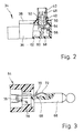
- FIG. 3 shows a jack plug 64 which is connected to the end of the connecting cable 12A and fits into a headphone socket on the cassette recorder 10A.
- An axial groove 68 is machined into a plug part 66, in which a leaf spring 70 is arranged to be freely bendable. The second end of the leaf spring is attached to the rear end of the plug part 66.
- the leaf spring 70 has a convex working section 72 protruding outwards from the groove 68.
- a strain gauge 76 is fastened on a bending section 74.
- the plug part 66 is fixed in a conventional plastic handle part 78.
- the resistance of the strain gauge 76 has two different values, depending on whether the working section 72 is fully moved into the groove 68 when the plug is inserted or protrudes from the groove 68 when the plug is removed.
- FIG. 4 shows a section through a mains socket 80 modified for monitoring purposes with a socket housing 82 and resilient socket parts 86, 88 carried by the latter via an insulating body 84 and which can work together with the pins of a mains plug.
- Passages 94 for the pins of the plug are provided in the bottom 90 of the plug receiving chamber 92 of the socket housing 82. Like passages 9.6 in the insulating body 84, these are aligned with the socket parts 86, 88.
- an actuating pin 98 extends transversely in the insulating body 84 into one of the passages 96 and works on a microswitch 100 fastened to the socket housing 82 and has a ramp surface 102 at the opposite end.
- the output signal of the microswitch 100 can be used to determine whether or not there is a plug in the socket, the socket still being able to pass on the mains voltage to a connected consumer.
- FIG. 5 shows a simple monitoring circuit for use with a socket strip which contains a plurality of modified mains sockets according to FIG. 4.
- each of the microswitches 100 is a changeover switch with a normally open contact and a normally closed contact.
- a spring 104 serves to bias a switching bridge 106 into an upper working position.
- the output contacts of each of the microswitches 100 are connected together via a bridge 108, and the output of a microswitch 100 is connected to the input of a subsequent microswitch (with the exception of the terminal microswitch), as can be seen in the drawing.
- a supply voltage which is provided by the monitoring unit 16, is applied to the first microswitch 100 via a line 110, while the last microswitch is connected to the monitoring unit via a further conductor 112.
- the conductors 110 and 112 together form a connecting cable which corresponds to the connecting cable 12D from FIG. 1.
- the conductor 112 is connected to the set terminal of a bistable multivibrator 114, and an alarm unit 116 is connected to its "1" output.
- a switch 118 connected to the reset terminal of the flip-flop 114, which can be formed by the lock switch 24 or is part of the same.
- An output-side OR gate 120 is connected with an input directly to that contact of the assigned microswitch 100 against which the switching bridge 106 is g e-pressed when the plug is inserted.
- the other contact of the microswitch 100 which is connected to the input of the switch unit by the switching bridge 106 in the unloaded state, is on the one hand directly connected to a second input of the OR element 66 and on the other hand via an inverter 122, a differentiating element 124 and one Diode 126 connected to a monostable multivibrator 128.
- the output of the latter is connected to a third input of the OR gate 120.
- the switching bridge 106 is moved out of the state shown in the wiring of a microswitch 100 shown in FIG. 6, the signal at the middle input of the OR gate 120 is omitted, but at the same time the output signal of the monostable multivibrator 128 is obtained, so that a total Signal at the output of the OR gate 120 is retained. If the switching bridge 106 is now quickly moved into its lower working position, as is readily possible when a plug is plugged into a mains socket, the bottom input of the OR gate 120 is subjected to a signal before the output signal of the monostable multivibrator 128 has ended. If, on the other hand, the switching bridge 106 is removed from the socket when a plug is removed from the socket
- Figure 6 underlying contact of the microswitch 100 moved away, so you get a voltage drop at the output of the OR gate 66 and thus triggering an alarm.
- FIG. 7 shows the essential part of the electrical circuit of a system for monitoring exhibited goods against theft, the basic structure of the circuit being similar to that already shown in FIG. 5, but additional measures have been taken to also ensure that the goods being monitored by the monitoring unit 16 are manipulated leading connecting cable to trigger an alarm.
- the socket strip shown in Figure 1 consists of a plurality of sockets 80 according to Figure 4, of which only the microswitch 100 are shown in Figure 7.
- a resistor 131 is connected via the plug contacts of the connecting cable 12D that can be connected to the input socket 14D, and a resistor 130 g is switched into the conductor 110 inside the socket strip 10D.
- the conductor 112 is connected to a ground line 134 via a further resistor 132. Via a further resistor 136, the signal on line 112 reaches one of the inputs of three differential amplifiers 138A, 138B and 13EC.
- the potential of the conductor 110 is applied to the second inputs thereof via voltage dividers formed by resistors 140A, B, C and 142A, B, C.
- the voltage dividers just mentioned are selected so that the reference voltages decrease from the differential amplifier 138A to the differential amplifier 138C.
- the above voltage divider are adjusted to the space formed by the resistors 130 to 132 the voltage divider such that an output signal is obtained at the output of the differential amplifier 138A, when the conductors 110 and 112 short-g at a tampering attempt can be e-closed, while an output signal at the differential amplifier 138B is obtained when one of the microswitches 100 briefly when the switching bridge is moved from one to the other working position or an interruption is caused in one of the conductors 110, 112.
- the opposite is provided as the differential amplifier 138A and 138B connected differential amplifier 138C, generates no output signal if the associated input terminal of the monitoring unit is not bridged by a resistor 131st
- the output signals the differential amplifiers 138B and 138C are combined by an AND gate 142.
- the output signal of the latter like the output signal of the differential amplifier 138A, is passed via an OR gate 144 to the set input of the bistable multivibrator 114 already mentioned with reference to FIG.
- a capacitor 146 is connected between the inputs of the differential amplifier 138 and the ground line 134.
- the capacitor 146 is slowly discharged, so that an operating state is temporarily obtained in which a signal is present at the outputs of both differential amplifiers 138B and 138C, so that an alarm is triggered.
- the capacitor 146 is constantly discharged, so that such an intermediate state is not reached, that is to say that no signal can be obtained at the output of the AND gate 142.
- the "1" output of the flip-flop 114 and an amplifier 148 excite the light-emitting diodes 20 associated with the input of the monitoring unit 16 under consideration.
- the output signals of the various toggle circuits 114 assigned to the inputs of the monitoring unit are combined via an OR gate 150, which controls an acoustic alarm unit 154 via an amplifier 152, to which the loudspeaker 22 belongs.
- the reset terminals of the flip-flops 114 are supplied with the supply voltage via an RC element 155, 157, so that an alarm can be cleared simply by switching the monitoring unit off and on again.
- the signal processing channels assigned to the other inputs of the monitoring unit 16, of which only the bistable flip-flops 114 are shown in FIG. 7, are constructed analogously as described above for the signal channel assigned to the input socket 14D, except that these signal channels do not contain their own voltage dividers, rather they receive them Reference voltages across conductors 156A, 156B and 156C.
- FIG. 8 shows details of the voltage supply for the circuit part shown in FIG. 7.
- a power supply 158 designed for low power is supplied with the mains voltage on the input side and provides a DC voltage on the output side. This output voltage is passed via two switching transistors 160 and 162 to a supply line 164, to which a voltage regulator 166 is also connected.
- the conductor 110 is connected to the output of the latter.
- a charge / discharge circuit for a dry accumulator 168 which has a charge resistor 170 and a discharge diode 172, is inserted between the switching transistors 160 and 162.
- the switching transistor 160 is opened; the corresponding base drive circuit comprises the series connection of a resistor 174 and a capacitor 176, through which the output terminals of the power supply 158 are connected.
- a protective diode 178 is inserted between the switching transistor 160 and the charge / discharge circuit for the dry accumulator 168.
- Its control circuit comprises a differential amplifier 180 which is supplied with the output voltage of the dry accumulator 168 via a high-resistance voltage divider with resistors 182, 184 and is also supplied with a constant reference voltage from a Zener diode 186 when the dry accumulator 168 reaches the limit a deep discharge is discharged.
- the Zener diode 186 is connected to the supply line 164 via a high-resistance voltage divider with resistors 188, 190.
- the output signal of the differential amplifier 180 is applied to the base of the switching transistor 162 via an RC element 181, 183.
- a capacitor 185 is connected to the output of the switch 24, the terminals of which are bridged by a high-resistance resistor 179.
- the capacitor 185 is connected to the conductor 132 via a further resistor 187 and to the base of the switching transistor 162 via a diode 189 and a Zener diode 191 connected in series therewith. If after a deep discharge of the dry accumulator 168 the connection to the electrical network is restored, the voltage at the output of the switch 24 increases only by a small amount, which is not sufficient to pull the switching transistor 162 into the closed state via the capacitor 185. For this reason, the base of transistor 162 is additionally connected directly to the output of switch 24 via a further Zener diode 193.
- 195 also designates a base resistance for the switching transistor 162.
- the signal input of the differential amplifier 180 is connected directly to the output of the power supply 158, the partial ratio of the voltage divider formed by the resistors 192 and 184 being set such that a signal input of the differential amplifier 180 is also still on receives a signal lying above a deep discharge state of the dry accumulator 168 if the output voltage of the power supply 158, which is only designed for low power, partially breaks down in the event of an alarm, since greater power is now to be delivered to the alarm unit 154.
- the switching transistor 162 thus remains closed under such operating conditions in any case.
- the lock switch 24 is inserted between the charge / discharge circuit for the dry accumulator 168 and the switching transistor 162. If the lock switch 24 is opened, the voltages on the supply line 164 and on the conductor 110 disappear. When the lock switch 24 is subsequently closed, a rising signal edge is then obtained on the conductor 110, which flank is generated by the voltage divider formed by the resistors 140C and 142C the reset terminals of the flip-flops 114 are given so that a triggered alarm is cleared.
- the RC link 155 ensures 157 for the fact that the flip-flop flip-flops 114 are only reset a predetermined time after the monitoring circuit has been switched on. This ensures that switching peaks occurring during the switch-on process, which could lead to the setting of one of the bistable flip-flops 114, cannot trigger a permanent alarm.
- the operation of an anti-theft device with monitoring of the connecting cable was described with reference to FIG. 7 with reference to a multiple socket strip.
- the monitoring of the cassette recorder 10A and the video recorder 10C is carried out quite analogously, with the only difference that in the connection cable 12A the strain gauge 76 built into the jack plug (see FIG. 3) replaces the series connection of a microswitch and the resistor 130 according to FIG.
- the microswitch 62 represents the equivalent of the microswitch 100 according to FIG. 7, and in series with the microswitch 62 a resistor (not shown in more detail) is arranged in the interior of the multiple plug 34 corresponds to Figure 7.
- FIG. 9 shows a further anti-theft device which works on an AC voltage basis.
- a sensing unit 200 e.g. similar to that explained with reference to FIGS. 2 and 4, can be installed in a plug or a socket, has a microswitch 202 that works mechanically with the goods to be monitored and a capacitor 204 connected in series.
- the sensing unit 200 is connected to the Input socket 210 of a monitoring circuit 212 connected.
- the monitoring circuit 212 contains an AC voltage source 214, via the output terminals of which two identical spans are connected, each having a resistor 216 and 218 and a capacitor 220 and 222 connected in series.
- a switch 224 Arranged in series with the capacitor 220 is a switch 224 which is resiliently biased into the closed position and which is forcibly opened when the connecting cable 226 comprising the conductors 206 and 208 is connected.
- the two inputs of a differential amplifier 228 are connected to the network nodes which are located between resistor 216 and capacitor 220 or resistor 218 and capacitor 222. Its output is connected via a diode 230 and a Zener diode 232 to the set input of a bistable multivibrator 234, which corresponds in function to the bistable multivibrators 114 according to FIG. 7 and on the output side in the manner described in FIG. 7 with an associated light-emitting diode and the common alarm unit is connected.
- the flip-flop 234 is also reset analogously to that described above with reference to FIG. 7.
- the capacitors 204, 220 and 222 have exactly the same electrical properties, in particular they have the same capacitance.
- switch 224 is closed and the inputs of differential amplifier 225 are acted upon by signals of the same amplitude and phase position. Then no output signal of the differential amplifier 228 is obtained.
- connection cable 226 If the connection cable 226 is properly inserted and the switch 202 is closed by the goods to be monitored, the capacitor 204 identical to the capacitor 220 takes over completely its function, so that there is still no signal at the output of differential amplifier 228.
- a switching window of the monitoring circuit is predetermined by the Zener diode 232, with which the ohmic resistance of the connecting cable 226 and production-related capacitance fluctuations of the various capacitors can be taken into account.
- the bistable flip-flop 234 is set by the first positive half-wave at the output of the differential amplifier 228.
- An alarm is also triggered when the connecting cable 226 is unplugged because, owing to the mechanical inertia of the switch 224 and the lack of a matching of the length of the plug contacts on the input socket 210 to the working stroke of the switch 224, either an intermediate state is briefly obtained in which the resistance 216 is not connected to any capacitor at all, or an intermediate state is obtained in which the two capacitors 204 and 220 are connected in parallel. In both intermediate states, the differential amplifier 228 is not subjected to the same signals at its input terminals.
- FIG. 10 shows the section of a connecting cable on the goods side, which can be used for monitoring items of clothing such as coats or jackets or also for monitoring other goods which do not have any electrical connection sockets but instead have a closed through opening such as a handle (for example handles of an internal combustion engine) saws, handles of porcelain jugs, etc.).
- a handle for example handles of an internal combustion engine
- saws handles of porcelain jugs, etc.
- the connecting cable 236 is at a distance from its free end forming a U-shaped loop section 238 embedded in a socket 240.
- a plug 242 is connected to the end of the connecting cable 236 and can be inserted with its two pins 244, 246 into sockets 248, 250 of the socket 240.
- a resistor 252 is soldered via the sockets 248, 250, one lead 254 of the resistor 252 being passed through the loop section 238 in a chain-like manner.
- the outermost cable section carrying the plug 242 is passed through the sleeve of a garment or the handle or handle of a product and then plugged into the socket 240 - after arming the monitoring circuit connected to the connecting cable 236, which is configured similarly to that described above with reference to FIGS. 5 and 7 to 9, a constant monitoring current flows through the connecting cable. Pulling the plug 242 out of the socket 240 results in the immediate triggering of an alarm, likewise cutting the cable 236 at any point and also violently cutting the socket 240 in the area between the sockets 248, 250 and the loop section 238.
- FIG. 11 shows a modification of the anti-theft device according to FIG. 7.
- the conductors connected to the network contacts 256, 258 of the individual sockets are designated 260 and 262.
- the normally closed contact 264 of a short-circuit or overcurrent monitor 266 is inserted into the conductor 260, the actuating coil 268 of which simultaneously actuates a normally closed signal contact 270 as well.
- the signal contact 270 is arranged in series with the microswitches 100.
- a short-circuit monitor which has a normally open signal contact, which is then connected upstream of the resistor 130 via the conductors 110, 112.
- the short circuit generated during cutting triggers the short-circuit monitor 266 and thus triggers an alarm as does the removal of a plug from the monitored power strip.
- the conductors 260 and 262 are only subjected to a low voltage, for the sake of simplicity the voltage on the conductors 110 and 112.
- the short-circuit monitor 266 is designed or set so that it does not respond when the switch on a device connected to the power strip is actuated, but when cutting a cable connected to the power strip. In the power supply shown in FIG.
- FIG. 12 shows an alternative embodiment of a deep discharge protection, which can be used instead of the components 180 ff. From FIG. 8. Corresponding components are again provided with the same reference symbols.
- a differential amplifier 196 is connected via the charging diode 178 and produces no output signal for as long as diode 178 is operated in the forward direction (presence of mains voltage and charging of accumulator 168). If the mains voltage fails, a voltage drop is obtained at the diode 178 and a signal is present at the output of the differential amplifier 196. The latter activates a frequency generator 197 and at the same time resets a counter 198, the counter terminal Z of which receives the pulses provided by the frequency generator 197. An output terminal of counter 198 of high significance is connected to the input of an inverter 180 ', the output signal of which is used via resistor 181 to control transistor 162.
- the frequency of the frequency generator 197 and the counter 198 are selected so that the output terminal of the counter 198 connected to the inverter 180 ' becomes high after a period of about 12 hours.
- the accumulator 168 is therefore no longer discharged.
- FIG. 13 shows a further monitoring circuit which, like the interruptions and short circuits shown in FIG. 7, is equally able to determine in the monitoring circuit.
- the current flowing through the resistor 131 and with the proper operative connection between the sensor and the goods at the same time via the resistor 130 is provided on a conductor 410 by the power supply (not shown in more detail) and generates a corresponding voltage drop at an input resistor 412 of the monitoring circuit.
- the base terminal of a transistor 418 is controlled via a voltage divider with resistors 414 and 416, which is high-resistance compared to resistor 412, with the time delay of turning on transistor 418 from occurrence a voltage across resistor 412, a capacitor 420 is connected between the base terminal of transistor 418 and ground.
- a further resistor 422 is connected into the collector-emitter path of transistor 418, which together with transistor 418 can bridge a resistor 424, which is high-resistance in comparison.
- the latter together with a resistor 426, forms a voltage divider connected between the conductor 410 and the ground rail 428, which is connected to the negative input terminal of a differential amplifier 430 and is supplied with the voltage across the resistor 412 via a diode 432.
- the second input terminal of the differential amplifier 430 is grounded via a resistor 434 and a reference voltage Uref is applied to it via a further resistor 436, which is lower than the supply voltage V on the conductor 410.
- the positive input terminal of the differential amplifier 430 is connected to the amplifier output g anc via a diode 438, so that the output signal of the amplifier 430 is self-sustaining.
- the collector-emitter path of a further transistor 440 is connected between the network nodes lying between the resistors 434 and 436 and the conductor 410.
- a resistor 424 connected in the conductor 410 together with a resistor 444 connected in series therewith and the resistors 131 and 412, drives the base terminal of the transistor 440, in such a way that the transistor 440 turns on when the current on the conductor 410 exceeds a predetermined threshold value, which indicates a short circuit between the conductors of the connecting cable 12.
- the positive input terminal of the differential amplifier 430 is thus brought to the higher potential Vcc on the conductor 4 1 0 so that the Dif reference amplifier 430 switches through in any case.
- the various voltage divider resistors are selected so that when the switch 100 is opened or the cable 12 is cut, the potential at the negative input terminal of the differential amplifier 430 drops so much that the voltage drops below the small reference voltage on the positive input and the differential amplifier 430 also switches through.
- the transistor 418 ensures that instead of the low-resistance resistor 422, the high-resistance resistor 424 lies between the negative input terminal of the differential amplifier 430 and the ground rail 428 before the connecting cable 12 is plugged in. This terminal is thus at such a high potential that no output signal from the differential amplifier 430 is obtained.
- FIGS. 14 to 24 lines which serve to supply power to circuits are generally distinguished from signal lines by small dashes.
- 310 represents a supply line for a monitoring channel designated overall by 312. This is connected via a plug connection 314 and a cable 316 to a sensor 318, which has a switch 320 mechanically cooperating with a product to be monitored and a switch 320 connected in series for this purpose Has resistor 322.
- a monitoring current is connected to the supply line 310 source 324, a detector circuit 326 and an alarm unit 328 connected.
- the latter can be a light, for example, while a central acoustic alarm is triggered by an output line 330 of the monitoring channel 312.
- the monitoring current increases, as shown at time t 0 in FIG. 16. It is therefore not possible to remove the goods from the exhibition space without the monitoring current changing its amplitude to smaller or larger values. These amplitude changes are determined in the detector circuit 326, and the output signal then provided triggers the alarm unit 328.
- FIG. 17 has a detector circuit D if- ferenzier gest 332, a monostable multivibrator ⁇ with the output signal with the period, the first input of an OR gate 336 and the input of an inverter 338 charged.
- the output of the inverter 338 is connected to a second input of the OR gate 336, and the output of the latter is connected to the one input of an AND gate 340.
- the output signal of the flip-flop 334 sets an bistable flip-flop 344 via an inverter 324, the "1" output of which is connected to the second input of the AND gate 340.
- the output of the latter is connected to the set terminal of a further bistable multivibrator 346, the "1" output of which provides the control signal for the alarm unit 328.
- the pulse generated by the rising current edge at the output of the differentiating circuit 332 reaches the set input S of the bistable multivibrator 346 via the OR gate 336 and the AND gate 340, and an alarm is triggered. If the monitoring circuit is interrupted during an attempted theft, the pulse generated by the falling current edge leads via the inverter 338 and likewise via the OR gate 336 and the AND gate 340 to trigger an alarm.
- the detector circuit 328 shown in FIG. 18 works very similarly to the detector circuit 326 according to FIG. 17, only the OR gate 336 and the inverter 338 are replaced by a full-wave rectifier 348, and the output of the latter is connected to the counter terminal Z of a binary counter 350. Its output terminal corresponding to the number "2" is connected to the set input of the bistable multivibrator 346.
- the monitoring current edge connected when a cable 316 connected to a sensor 318 is inserted is masked out by the binary counter 350 and therefore does not lead to an alarm. Every further change in the level of the monitoring current towards smaller or larger values leads to the further counting of the binary counter 350 to the number “2” and thus to the setting of the bistable multivibrator 346 and to trigger an alarm.
- FIG. 19 and the other figures circuits which have already been explained above with reference to FIGS. 14 to 18 are again provided with the same reference symbols.
- the monitoring current source 324 simultaneously transfers a reference current to the detector circuit 326, which represents the setpoint for the monitoring current when the monitoring path is properly closed.
- a current monitor circuit 352 is connected into the monitoring circuit, which generates a continuous output signal from the point in time at which a monitoring current has flowed through the sensor 318.
- the detector circuit 326 in turn always provides a control signal for the alarm unit 328 if the current value of the monitoring current deviates upwards or downwards from the reference current.
- the output signal of the current monitor circuit 352 serves to close a controllable switch 354 which is connected to the supply line of the Detector circuit 326 is inserted.
- the detector circuit 326 thus does not generate a control signal for the alarm unit 328 if the monitoring channel 312 was not already occupied when the entire monitoring system was switched on.
- controllable switch 354 can be inserted into the reference current line, which runs from the monitoring current source 324 to the detector circuit 326.
- the detector circuit is then acted upon by a reference current signal assigned to an open circuit.
- the current monitor circuit shown in FIG. 21 has a resistor 356 connected to the monitoring circuit and one with its input terminals via the latter connected differential amplifier 358.
- the output of the latter is connected to the set terminal of a bistable multivibrator 360, and its "1" output controls with the interposition of an amplifier 362, the switch 354.
- the flip-flop 360 is reset again when the entire network supply of the monitoring system is switched on for the first time.
- the embodiment according to FIG. 22 is similar to that according to FIG. 20, but the switch 354 is not activated as a function of the monitoring current but as a function of a separate arming current, the circuit of which is closed via a separate contact of the plug connection 314 when a cable is connected. In this embodiment, an alarm is thus triggered even if the sensor 320 has not been properly attached to the goods, that the switch 320 is not closed. Interruptions in cable 316 are also reliably detected.
- a current monitor circuit 3 5 2 is provided, which can be designed in the same way as that shown in FIG. 21, in a simplified embodiment but can also have only one capacitor 364 with an associated charging resistor 366. The capacitance of the capacitor 364 is dimensioned such that the switch 354 is kept closed when the plug connection 314 is released until the detector circuit 326 has generated its alarm signal.
- the current sinks are not shown in any more detail; it is understood that the various circuits are closed in a known manner via the ground rail.
- FIG. 23 shows a monitoring channel constructed from analog switching elements, which is constructed similarly to the monitoring channel according to FIG. 22, but with the difference that the capacitor charged via the additional contact of the plug connection 314 is used directly as an emergency reference current source, which connects the detector circuit after the Disconnecting the connector 314 still holds for a sufficient period of time to generate an alarm.
- FIG. 23 also shows the negative supply line 311.
- the monitoring channel contains a differential amplifier 368, which provides the control signal for the alarm unit 328 and is also self-holding by a feedback diode 370.
- the positive input terminal of the differential amplifier 368 is assigned an interference suppression circuit which comprises a resistor 372 and an interference suppression capacitor 354. If the input of the monitoring channel is not occupied, the positive input of the differential amplifier 368 is biased to a predetermined potential by two resistors 376, 378, while the negative input of the differential amplifier 368 is grounded via a resistor 380. Under these conditions No signal is received at the output of differential amplifier 368.
- the negative input terminal of the differential amplifier 368 is brought to a potential which is still less than than via the voltage divider formed by the resistor 380 and a further resistor 382 the potential then prevailing at the positive input terminal of the differential amplifier 368.
- the latter is increased compared to the working state when the input is not occupied, since the resistor 322 and the resistor 382 are now connected in parallel with the resistor 376. No alarm is generated even under these conditions.
- a capacitor 383 is connected across the resistor 380 and charges when the plug connection 314 is closed.
- the switch 320 If the switch 320 is opened, the cable 316 is cut or the connector 314 is disconnected, the potential at the positive input of the differential amplifier 368 quickly drops back to the value it had before the sensor was connected.
- the time constant of the RC element formed by resistor 380 and capacitor 383 is thus chosen so that differential amplifier 368 has sufficient time to control.
- the negative input terminal of the differential amplifier 368 is connected via a Zener diode 384 and an oppositely polarized diode 386 to the contact of the plug connector 314, via which the monitoring current returns to the monitoring channel 312.
- the Zener diode 384 is selected with such a breakdown voltage that it still blocks when the monitoring path is in the correct state, but breaks through in the event of a short circuit between the conductors of the cable 316.
- the negative input of the differential amplifier 368 is again at a higher potential than the positive input, since this potential is limited by a further Zener diode 388 to a predetermined value which is smaller than that in the event of a short circuit on the negative input terminal of the differential amplifier .368 potential value obtained.
- a resistor 385 separates the diode 386 from the Zener diode 388.
- the different resistances have the following values:
- the Zener diode 384 has a breakdown voltage of 2 V
- the Zener diode 388 has a breakdown voltage of 6 V.
- FIG. 24 components which correspond in terms of function to components already explained with reference to FIG. 23 are again provided with the same reference symbols.
- An essential difference between the embodiment according to FIG. 24 and that according to FIG. 23 is that the plug connection 314 need only have two contacts.
- the positive end of the resistor 382 is connected directly to the supply line 310, and the capacitor 383 is now connected between the contact of the plug connection 314 that receives the monitoring current and the network nodes located between the resistors 376 and 378.
- a further Zener diode 390 is provided in series with a discharge resistor 392 for the capacitor 383.
- the different resistors have the following size:
- the Zener diode 384 is designed for a breakdown voltage of 4.5 V, the Zener diode 388 for a breakdown voltage of 4.0 V and the Zener diode 390 for a breakdown voltage of 3 V. .
- monitoring channels do not have to be switched off by blind plugs or the like. When using such blind plugs, new goods cannot be connected to the monitoring system without temporarily switching them off.
- unused monitoring channels are automatically switched off when the system is switched on. These channels can then be activated later simply by connecting them to a monitoring sensor, whereby no additional measures need to be taken.
- a light indicator can be connected to the output of the bistable multivibrator 344 of FIG. 17 or to the least significant output of the counter 350 of FIG. 18, as indicated schematically at 345.
- this indicator does not light up after plugging in the connecting cable of a sensor, this indicates that either the switch 320 of the sensor unit 318 is not closed (insufficient contact between sensor and goods) or an interruption in the connecting cable 316 or poor contact at the plug connection 314 is present.
Landscapes
- Physics & Mathematics (AREA)
- General Physics & Mathematics (AREA)
- Burglar Alarm Systems (AREA)
Priority Applications (1)
| Application Number | Priority Date | Filing Date | Title |
|---|---|---|---|
| AT83112050T ATE27661T1 (de) | 1983-01-26 | 1983-12-01 | Diebstahlsicherung. |
Applications Claiming Priority (4)
| Application Number | Priority Date | Filing Date | Title |
|---|---|---|---|
| DE3302459 | 1983-01-26 | ||
| DE19833302459 DE3302459A1 (de) | 1982-05-07 | 1983-01-26 | Diebstahlsicherung fuer ausgestellte waren |
| DE19833314187 DE3314187A1 (de) | 1983-04-19 | 1983-04-19 | Diebstahlsicherung fuer waren |
| DE3314187 | 1983-04-19 |
Publications (2)
| Publication Number | Publication Date |
|---|---|
| EP0116701A1 true EP0116701A1 (fr) | 1984-08-29 |
| EP0116701B1 EP0116701B1 (fr) | 1987-06-03 |
Family
ID=25807810
Family Applications (1)
| Application Number | Title | Priority Date | Filing Date |
|---|---|---|---|
| EP83112050A Expired EP0116701B1 (fr) | 1983-01-26 | 1983-12-01 | Dispositif antivol |
Country Status (2)
| Country | Link |
|---|---|
| EP (1) | EP0116701B1 (fr) |
| DE (1) | DE3371951D1 (fr) |
Cited By (7)
| Publication number | Priority date | Publication date | Assignee | Title |
|---|---|---|---|---|
| DE19528178A1 (de) * | 1995-08-01 | 1997-02-06 | M S E Gmbh | Überwachungssystem |
| DE19612374C1 (de) * | 1996-03-28 | 1997-08-21 | Reinhold Ott | Zentraleinheit für eine Anlage zur Sicherung von Waren gegen Diebstahl |
| DE19808252A1 (de) * | 1998-02-27 | 1999-09-09 | Ott | Zentraleinheit für eine Anlage zur Sicherung von Waren gegen Diebstahl |
| WO2003042944A1 (fr) | 2001-11-13 | 2003-05-22 | Saaa - Systemes D'automatismes D'alarmes Automatiques | Dispositif de securite filaire pour la detection du vol d'un objet a proteger et procede de fonctionnement. |
| DE19655081C5 (de) * | 1996-03-28 | 2010-11-04 | Reinhold Waterloo Ott | Zentraleinheit für eine Anlage zur Sicherung von Waren gegen Diebstahl |
| US20110043339A1 (en) * | 2009-08-19 | 2011-02-24 | Intelleflex Corporation | RF device with tamper detection |
| CN113825335A (zh) * | 2021-09-10 | 2021-12-21 | 扬州中宏电力科技有限公司 | 一种基于物联网的远程防盗变压器整流器 |
Families Citing this family (10)
| Publication number | Priority date | Publication date | Assignee | Title |
|---|---|---|---|---|
| FR2625581A1 (fr) * | 1988-01-05 | 1989-07-07 | Jaeger | Detecteur de bris de glace pour vehicules automobiles |
| DE8805281U1 (de) * | 1988-04-21 | 1989-04-13 | Zander, Hans, 4836 Herzebrock | Sicherungsadapter |
| DE9001828U1 (de) * | 1990-02-16 | 1990-05-10 | Ott, Reinhold, 70565 Stuttgart | Zentraleinheit für eine Diebstahlsicherungsanlage |
| NL9100035A (nl) * | 1991-01-11 | 1992-08-03 | Ir Jacob Smit | Een diefstal preventie systeem. |
| DE9101296U1 (de) * | 1991-02-02 | 1991-05-23 | George, Roman A., Dipl.-Ing., 10961 Berlin | Fremdspannungsstecker zur Versorgung und Sicherung elektrisch betriebener Geräte |
| DE9201087U1 (de) * | 1992-01-30 | 1992-06-17 | Zander, Hans, 33442 Herzebrock-Clarholz | Stromversorgungseinheit für eine Video-Kamera o.dgl. |
| US5726627A (en) | 1995-05-16 | 1998-03-10 | Roger A. Kane | Security system with intermittent alarm location detection |
| DE19655316C5 (de) * | 1996-03-28 | 2013-01-31 | Ott Security Systems Inc. | Zentraleinheit für eine Anlage zur Sicherung von Waren gegen Diebstahl |
| EP1093743A3 (fr) | 1999-10-22 | 2003-07-09 | Reinhold Ott | Dispositif pour protéger un article contre le vol |
| DE202009015635U1 (de) * | 2009-11-24 | 2011-04-14 | Zander, Oliver | Sicherungsadapter zum Sichern kompakter Ausstellungsstücke mit geringerem Platzangebot |
Citations (7)
| Publication number | Priority date | Publication date | Assignee | Title |
|---|---|---|---|---|
| US3253270A (en) * | 1963-08-02 | 1966-05-24 | Downer Frank | Theft alarm for shoplift prevention |
| US3440636A (en) * | 1966-01-11 | 1969-04-22 | Michael T Sliman | Sensing resistance device |
| US3444547A (en) * | 1965-10-08 | 1969-05-13 | Gefco Mfg Corp | Anti-shoplifting device |
| DE2412145A1 (de) * | 1973-03-14 | 1974-10-24 | Steven Grant Marshall | Alarmsystem |
| GB1389009A (en) * | 1971-05-04 | 1975-04-03 | Emi Ltd | Theft alarm systems |
| DE2854434A1 (de) * | 1978-12-16 | 1980-06-19 | Burkhard Zuelow | Diebstahlsicherungseinrichtung fuer insbesondere verkaufsgegenstaende |
| DE3302459A1 (de) * | 1982-05-07 | 1983-11-10 | Reinhold 7000 Stuttgart Ott | Diebstahlsicherung fuer ausgestellte waren |
-
1983
- 1983-12-01 EP EP83112050A patent/EP0116701B1/fr not_active Expired
- 1983-12-01 DE DE8383112050T patent/DE3371951D1/de not_active Expired
Patent Citations (7)
| Publication number | Priority date | Publication date | Assignee | Title |
|---|---|---|---|---|
| US3253270A (en) * | 1963-08-02 | 1966-05-24 | Downer Frank | Theft alarm for shoplift prevention |
| US3444547A (en) * | 1965-10-08 | 1969-05-13 | Gefco Mfg Corp | Anti-shoplifting device |
| US3440636A (en) * | 1966-01-11 | 1969-04-22 | Michael T Sliman | Sensing resistance device |
| GB1389009A (en) * | 1971-05-04 | 1975-04-03 | Emi Ltd | Theft alarm systems |
| DE2412145A1 (de) * | 1973-03-14 | 1974-10-24 | Steven Grant Marshall | Alarmsystem |
| DE2854434A1 (de) * | 1978-12-16 | 1980-06-19 | Burkhard Zuelow | Diebstahlsicherungseinrichtung fuer insbesondere verkaufsgegenstaende |
| DE3302459A1 (de) * | 1982-05-07 | 1983-11-10 | Reinhold 7000 Stuttgart Ott | Diebstahlsicherung fuer ausgestellte waren |
Cited By (9)
| Publication number | Priority date | Publication date | Assignee | Title |
|---|---|---|---|---|
| DE19528178A1 (de) * | 1995-08-01 | 1997-02-06 | M S E Gmbh | Überwachungssystem |
| DE19612374C1 (de) * | 1996-03-28 | 1997-08-21 | Reinhold Ott | Zentraleinheit für eine Anlage zur Sicherung von Waren gegen Diebstahl |
| DE19612374C5 (de) * | 1996-03-28 | 2006-03-16 | Reinhold Waterloo Ott | Zentraleinheit für eine Anlage zur Sicherung von Waren gegen Diebstahl |
| DE19655081C5 (de) * | 1996-03-28 | 2010-11-04 | Reinhold Waterloo Ott | Zentraleinheit für eine Anlage zur Sicherung von Waren gegen Diebstahl |
| DE19808252A1 (de) * | 1998-02-27 | 1999-09-09 | Ott | Zentraleinheit für eine Anlage zur Sicherung von Waren gegen Diebstahl |
| WO2003042944A1 (fr) | 2001-11-13 | 2003-05-22 | Saaa - Systemes D'automatismes D'alarmes Automatiques | Dispositif de securite filaire pour la detection du vol d'un objet a proteger et procede de fonctionnement. |
| US20110043339A1 (en) * | 2009-08-19 | 2011-02-24 | Intelleflex Corporation | RF device with tamper detection |
| US9082057B2 (en) * | 2009-08-19 | 2015-07-14 | Intelleflex Corporation | RF device with tamper detection |
| CN113825335A (zh) * | 2021-09-10 | 2021-12-21 | 扬州中宏电力科技有限公司 | 一种基于物联网的远程防盗变压器整流器 |
Also Published As
| Publication number | Publication date |
|---|---|
| EP0116701B1 (fr) | 1987-06-03 |
| DE3371951D1 (en) | 1987-07-09 |
Similar Documents
| Publication | Publication Date | Title |
|---|---|---|
| EP0116701B1 (fr) | Dispositif antivol | |
| DE69123263T2 (de) | Batterieschutzsystem | |
| EP0563787B1 (fr) | Circuit de surveillance pour dispositif de sécurité commandé par ordinateur | |
| DE19512266A1 (de) | Vorrichtung zum Schutz einer elektronischen Schaltung vor Manipulation | |
| DE102010063783A1 (de) | Feldgerät mit einer Batterieeinheit | |
| DE3302459A1 (de) | Diebstahlsicherung fuer ausgestellte waren | |
| EP2136343B1 (fr) | Surveillance de conduite d'interrupteurs de fumée | |
| DE2636099C2 (de) | Vorrichtung zur Überwachung und Sicherung, insbesondere Diebstahlsicherung, von Fahrzeugen | |
| EP0505774B1 (fr) | Dispositif de commutation de sécurité | |
| DE60017311T2 (de) | Verfahren zur Überwachung der Endstellung eines mobilen Elements und Vorrichtung zur Durchführung des Verfahrens | |
| DE3439015C2 (fr) | ||
| DE2500759A1 (de) | Brandschutzanlage | |
| DE69100664T2 (de) | Steuervorrichtung zum elektrischen Speisen von mehreren elektrischen Geräten von einer Gleichstromquelle aus. | |
| EP1480239A2 (fr) | Procédé d'actionner et circuit de surveillance pour un interrupteur de position électronique-mécanique | |
| EP0292759B1 (fr) | Dispositif anti-vol pour véhicules automobiles | |
| DE19503732C2 (de) | Diebstahlsicherungsvorrichtung für elektrische Geräte und Maschinen | |
| DE19518752A1 (de) | Diebstahlsicherungsanlage | |
| DE4443274C2 (de) | Vorrichtung mit wenigstens einem Motorblockschloß | |
| DE2412145A1 (de) | Alarmsystem | |
| DE4422296A1 (de) | Elektronisches Sicherheitsschaltnetzwerk | |
| DE3314187A1 (de) | Diebstahlsicherung fuer waren | |
| DE3842053A1 (de) | Schaltung fuer die ueberwachung von mit gleichstrom betriebenen elektronischen alarmanlagen mit einer meldelinie | |
| DE69916984T2 (de) | Anordung zur Ermittlung einer Unterbrechung in einer elektrischen Leitung, inbesondere einer Telefonleitung | |
| DE8813233U1 (de) | Steckdose zur Sicherung von elektrischen und elektronischen Geräten | |
| DE2713280B2 (de) | Feuermeldeanlage mit mindestens einer zweidrähtigen Meldelinie für gleichspannungsversorgte Ionisationsfeuermelder |
Legal Events
| Date | Code | Title | Description |
|---|---|---|---|
| PUAI | Public reference made under article 153(3) epc to a published international application that has entered the european phase |
Free format text: ORIGINAL CODE: 0009012 |
|
| AK | Designated contracting states |
Designated state(s): AT BE CH DE FR GB IT LI NL SE |
|
| 17P | Request for examination filed |
Effective date: 19850223 |
|
| 17Q | First examination report despatched |
Effective date: 19860128 |
|
| GRAA | (expected) grant |
Free format text: ORIGINAL CODE: 0009210 |
|
| AK | Designated contracting states |
Kind code of ref document: B1 Designated state(s): AT BE CH DE FR GB IT LI NL SE |
|
| REF | Corresponds to: |
Ref document number: 27661 Country of ref document: AT Date of ref document: 19870615 Kind code of ref document: T |
|
| REF | Corresponds to: |
Ref document number: 3371951 Country of ref document: DE Date of ref document: 19870709 |
|
| ITF | It: translation for a ep patent filed | ||
| ET | Fr: translation filed | ||
| PLBI | Opposition filed |
Free format text: ORIGINAL CODE: 0009260 |
|
| PLBI | Opposition filed |
Free format text: ORIGINAL CODE: 0009260 |
|
| 26 | Opposition filed |
Opponent name: REHDER PHYSIK GMBH Effective date: 19880123 |
|
| 26 | Opposition filed |
Opponent name: TELE-SECURITY-FOTO GMBH Effective date: 19880302 Opponent name: REHDER PHYSIK GMBH Effective date: 19880123 |
|
| NLR1 | Nl: opposition has been filed with the epo |
Opponent name: REHDER PHYSIK GMBH |
|
| NLR1 | Nl: opposition has been filed with the epo |
Opponent name: TELE-SECURITY-FOTO GMBH |
|
| PLBN | Opposition rejected |
Free format text: ORIGINAL CODE: 0009273 |
|
| STAA | Information on the status of an ep patent application or granted ep patent |
Free format text: STATUS: OPPOSITION REJECTED |
|
| 27O | Opposition rejected |
Effective date: 19890410 |
|
| NLR2 | Nl: decision of opposition | ||
| ITTA | It: last paid annual fee | ||
| EAL | Se: european patent in force in sweden |
Ref document number: 83112050.6 |
|
| REG | Reference to a national code |
Ref country code: GB Ref legal event code: IF02 |
|
| PGFP | Annual fee paid to national office [announced via postgrant information from national office to epo] |
Ref country code: GB Payment date: 20021127 Year of fee payment: 20 Ref country code: FR Payment date: 20021127 Year of fee payment: 20 Ref country code: BE Payment date: 20021127 Year of fee payment: 20 |
|
| PGFP | Annual fee paid to national office [announced via postgrant information from national office to epo] |
Ref country code: SE Payment date: 20021203 Year of fee payment: 20 |
|
| PGFP | Annual fee paid to national office [announced via postgrant information from national office to epo] |
Ref country code: CH Payment date: 20021210 Year of fee payment: 20 Ref country code: AT Payment date: 20021210 Year of fee payment: 20 |
|
| PGFP | Annual fee paid to national office [announced via postgrant information from national office to epo] |
Ref country code: DE Payment date: 20021230 Year of fee payment: 20 |
|
| PGFP | Annual fee paid to national office [announced via postgrant information from national office to epo] |
Ref country code: NL Payment date: 20021231 Year of fee payment: 20 |
|
| PG25 | Lapsed in a contracting state [announced via postgrant information from national office to epo] |
Ref country code: LI Free format text: LAPSE BECAUSE OF EXPIRATION OF PROTECTION Effective date: 20031130 Ref country code: GB Free format text: LAPSE BECAUSE OF EXPIRATION OF PROTECTION Effective date: 20031130 Ref country code: CH Free format text: LAPSE BECAUSE OF EXPIRATION OF PROTECTION Effective date: 20031130 |
|
| PG25 | Lapsed in a contracting state [announced via postgrant information from national office to epo] |
Ref country code: NL Free format text: LAPSE BECAUSE OF EXPIRATION OF PROTECTION Effective date: 20031201 Ref country code: AT Free format text: LAPSE BECAUSE OF EXPIRATION OF PROTECTION Effective date: 20031201 |
|
| REG | Reference to a national code |
Ref country code: GB Ref legal event code: PE20 |
|
| BE20 | Be: patent expired |
Owner name: *OTT REINHOLD Effective date: 20031201 |
|
| REG | Reference to a national code |
Ref country code: CH Ref legal event code: PL |
|
| NLV7 | Nl: ceased due to reaching the maximum lifetime of a patent |
Effective date: 20031201 |
|
| EUG | Se: european patent has lapsed |