EP0114284A2 - Vorrichtung zum kontinuierlichen Messen der Form des Querprofils des Nutzteiles des Kopfes von mindestens einer Eisenbahnschiene - Google Patents
Vorrichtung zum kontinuierlichen Messen der Form des Querprofils des Nutzteiles des Kopfes von mindestens einer Eisenbahnschiene Download PDFInfo
- Publication number
- EP0114284A2 EP0114284A2 EP83112398A EP83112398A EP0114284A2 EP 0114284 A2 EP0114284 A2 EP 0114284A2 EP 83112398 A EP83112398 A EP 83112398A EP 83112398 A EP83112398 A EP 83112398A EP 0114284 A2 EP0114284 A2 EP 0114284A2
- Authority
- EP
- European Patent Office
- Prior art keywords
- rail
- feelers
- head
- probes
- frame
- Prior art date
- Legal status (The legal status is an assumption and is not a legal conclusion. Google has not performed a legal analysis and makes no representation as to the accuracy of the status listed.)
- Granted
Links
- 238000005259 measurement Methods 0.000 claims abstract description 13
- 239000000523 sample Substances 0.000 claims description 40
- 238000006073 displacement reaction Methods 0.000 description 5
- 235000001674 Agaricus brunnescens Nutrition 0.000 description 2
- 206010016275 Fear Diseases 0.000 description 1
- 230000006835 compression Effects 0.000 description 1
- 238000007906 compression Methods 0.000 description 1
- 230000000694 effects Effects 0.000 description 1
- 239000000463 material Substances 0.000 description 1
- 230000000149 penetrating effect Effects 0.000 description 1
- 230000000284 resting effect Effects 0.000 description 1
- 238000005096 rolling process Methods 0.000 description 1
- 230000001131 transforming effect Effects 0.000 description 1
Images


Classifications
-
- E—FIXED CONSTRUCTIONS
- E01—CONSTRUCTION OF ROADS, RAILWAYS, OR BRIDGES
- E01B—PERMANENT WAY; PERMANENT-WAY TOOLS; MACHINES FOR MAKING RAILWAYS OF ALL KINDS
- E01B31/00—Working rails, sleepers, baseplates, or the like, in or on the line; Machines, tools, or auxiliary devices specially designed therefor
- E01B31/02—Working rail or other metal track components on the spot
- E01B31/12—Removing metal from rails, rail joints, or baseplates, e.g. for deburring welds, reconditioning worn rails
Definitions
- the present invention relates to continuous measurement on the way of the shape of the transverse profile of the useful portion of the head of a rail of a railroad track.
- useful portion of the mushroom is meant that serving as a support for vehicle wheels and in particular the running surface, the leaves and the upper part of the inner face of the rail.
- Patent CH 606.619 which describes a measuring device comprising a series of feelers arranged side by side around the running table, the fillet and the inner face of the rail head, has already attempted to meet this need.
- the relative movements with respect to a carrier trolley guided along the rails and serving as a reference base are detected by measurement sensors of a supposedly known type, capable of delivering an output signal proportional to said displacements of the probes.
- the probes used in this case are not described in this patent, but are only illustrated in a purely schematic manner.
- the present measurement device a & Lon the invention tends to remedy this major drawback of existing devices and is distinguished by the characteristics listed in claim 1.
- the device according to the invention offers the advantage of allowing the measurement, in the same plane perpendicular to the axis of the rails, of a sufficient number of generators to obtain a complete and faithful image of the rolling surface, of the leaves of the rail and the upper part of the inside of this rail.
- this relatively simple mechanical solution has a small footprint so that even in work it does not encroach on the template of free obstacles and thus allows continuous measurement even in the switches.
- the possibility of mounting the same number of sensors symmetrically with respect to the axis of the rails makes it possible, if desired, to measure the external leave and the upper part of the external face of the rail.
- the additional feelers necessary for this measurement of the external part of the rail are retractable independently of the other feelers to allow obstacles which may arise in the track to be avoided.
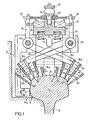
- two measuring devices 1, associated with each of the rows of rails 2, 2 'of a railway track are mounted using jacks 3, 3' on a carriage comprising flanged wheels 4 resting on the rails.
- This carriage formed of side members 5 and cross members 6 is connected to a rail vehicle for its movement along the railway track.
- Each device is articulated on the carriage so as to be able to move laterally and vertically with respect thereto.
- Each measuring device 1, l comprises a guide frame formed by a guide dihedral 7 comprising a horizontal bearing face 8 intended to come into contact, in the service position, with the central zone of the tread table 9 of the rail and a vertical support face 10 intended to come into contact, always in the service position, with the lower part of the internal lateral face 11 of the head 12 of the rail.
- This dihedral 7 constitutes a reference base for measuring the profile of the rail and the bearing faces 8 and 10 can be assimilated to measuring probes and used for determining the transverse profile of the rail.
- the bearing faces 8, 10 are preferably carried by shoes or pads 8a, 10a respectively, articulated along axes perpendicular to the longitudinal axis of the rail on the dihedron 7.
- Each measuring device 1, 1 ' is also secured to a beam 13, 13' connected by means of a jack 14, 14 'to a support 15 secured to the carriage 5, 6.
- each measuring device 1, l ' is applied vertically and laterally against the rail by means of the bearing faces 8, 10 of the frame 7 with a force determined by the action of the jacks 3, 3 '; 14, 14 '.
- the dihedral or frame 7 serves as a support for a set of mechanical probes 16, 16a ... 16th and 17a ... 17th each comprising a porctual contact member 20 intended to come into contact with the surface of the head 12 of the rail in a narrow area, transverse to rail 2, but preferably all located in the same plane normal to the longitudinal axis of the rail.
- Each contact member 20, as well as the bearing faces 8, 10 rest in the service position, on a different generator of the head of the rail.
- the number of probes 16, 17 is such, for example between 6 and 12, that it makes it possible to measure a number of generators sufficient to faithfully reconstruct the shape of this profile.
- the ten feelers 16, 17 are distributed uniformly over the entire periphery of the rail head, that is its tread table and its internal and external leaves, as well as the upper part of the internal flank of the rail head.
- Each mechanical probe 16, 17 is carried by two arms 18, respectively 19, pivoted on two axes 21, 21a respectively, integral with the frame 7 and extending parallel to the longitudinal axis of the rail 2 when the frame 7 is in the position of service guided by its pads 8, 10 on the rail.
- the arms of the probes 16, 17 are nested one inside the other thus forming a very compact assembly, compact and allowing the positioning of all the point contact members 20 in the same plane normal to the longitudinal axis of the rail.
- the probes are nested pair by pair, but in other examples not illustrated, the probes could be nested individually in each other.
- Each probe is subjected to the action of at least one spring 22, tending to maintain its point contact member 20 in contact with the surface of the rail head.
- These springs 22 are for example compression springs bearing on the one hand on a block 23 secured to the frame 7 and on the other hand on one of the arms 18, 19 of a probe.
- each probe is integral with a control lever 24, respectively 25, extending vertically above the frame 7 and the upper end of these levers is provided with a ball roller 26.
- Each lever 24, 25 is connected to the movable member 27 of a sensor 28 transforming the angular displacements res of these levers 24, 25 in electrical signals proportional to the displacements of the probes and which are therefore representative of the position of the point of contact 20 of the probe 16, 17 with the surface of the head 12 of the rail 2.
- the whole of this mechanical measuring device is very compact and can be housed inside the free obstacle gauge G of the track.
- the exact profile can be measured, using 6 to 12 measuring points for example, of a cross section of the useful part of the head of the rail representing the tread and the leaves internal and external and the upper part of the internal side of the rail head.
- 6 to 12 measuring points for example, of a cross section of the useful part of the head of the rail representing the tread and the leaves internal and external and the upper part of the internal side of the rail head.
- the measuring device is located inside the clear gauge G and can therefore be moved along the entire route of a railroad track.
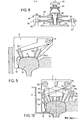
- the device illustrated is equipped with an automatic retraction system for the probes 16, 17 controlled by the presence of a counter rail 29.
- This automatic retraction system comprises a control member 30, the lower part of which is intended to cooperate with a counter rail 29, articulated on a cross-member 6 of the carriage at 31 and secured to a lever 32 articulated on the beam 13.
- this system also includes a second member maneuver 33 intended to cooperate with a counter rail associated with the other rail file, also pivoted, at 34, on the cross member 6 of the carriage and secured to a lever 35 articulated on the beam 13 '.
- one of the control members 30, 33 when, during the movement of the carriage along the railway track, one of the control members 30, 33 is moved under the effect of a counter rail, towards the outside of the track, it is that is to say in the direction of the rail 2, 2 ′ with which it is associated, it causes a relative displacement of the beams 13, 13 ′ with respect to each other causing a reduction in the distance separating the measuring devices 1, 1 'relating to each of the rows of rails 2, 2'.
- Each control plate 45 is slidably mounted on the frame 7 of its measuring device using screws 46.
- the lateral edges of this plate 45 include notches 47 in which are disposed, in the rest position of the plate 45, the rollers 26 of the levers 24, 25 of the feelers 16, 17.
- control members 30, 33 cause the measurement device 1 to be raised, the by a cam 48 of these control members cooperating with a stop 49 carried by the measurement device.
- the feelers are retracted and the measuring devices are raised automatically by the action of a counter rail on one of the control members 30, 33 during the movement of the carriage along the track.
- Contact of one of the control members 30, 33 with the counter-rail 29 which is associated with it also prevents the measuring device from penetrating laterally into the gap in the switches.
- the measuring device further comprises a manual retraction system sensors 17d and 17 e in contact with the outer sidewall of the rail. These probes 17d and 17e must in fact be able to be raised selectively to allow the passage of the measuring device in work, the other probes remaining in contact with the rail, in level crossings for example.
- This manual retraction system comprises a second control plate 50 slidingly mounted on the frame 7 parallel to the first plate 45. This plate 50 is subjected to the action of a return spring 51 and to a connecting rod 52 connected by a connection not illustrated to a manual control member. One of the lateral edges of this plate 50 has notches 52 one of the sides of which cooperates with rollers 54 carried by the levers 24 of the probes 17d and 17e. Thus, a movement of this plate 50 enables the probes 17d and 17e to be selectively retracted as illustrated diagrammatically in FIG. 10.
- this comprises two axes 21, 21a for pivoting the probes 16, 17 which are located symmetrically with respect to a vertical plane passing through the longitudinal axis of the rail 2.
- these axes 21, 21a can very well be arranged asymmetrically with respect to this plane.
- the measuring device has a single axis 55, offset from the vertical plane passing through the longitudinal axis of the rail 2, around which T all the probes 56a, 56b .. 56x are rotated. At least two of these feelers 56 are in contact with points on the surface of the rail head located on the other side of this vertical plane of the rail 2.
- the measuring device generally comprises at least three feelers coming into contact with the tread of the rail and at least two feelers in contact with the internal leave and the internal upper side of the rail.
- this device also comprises at least two feelers in contact with the external leave of the rail.
- the articulated part or parts 8 forming the bearing surface of the dihedron 7 on the rail can simultaneously define a reference base for measuring the longitudinal undulations of the surface of the rail head.
- the pads 8a articulated on the dihedron 7 are arranged on either side of the group of probes 16, 17 and this distance is sufficient to create the reference base of a measuring device as described for example in the European patent No alone (application No.83110242.1).
- this very compact measuring device can not only measure the transverse profile of a rail but also the longitudinal undulations, short or long, of its tread table.
Landscapes
- Engineering & Computer Science (AREA)
- Mechanical Engineering (AREA)
- Architecture (AREA)
- Civil Engineering (AREA)
- Structural Engineering (AREA)
- Length Measuring Devices With Unspecified Measuring Means (AREA)
- A Measuring Device Byusing Mechanical Method (AREA)
- Paper (AREA)
- Adjustment Of The Magnetic Head Position Track Following On Tapes (AREA)
- Measurement Of Length, Angles, Or The Like Using Electric Or Magnetic Means (AREA)
Priority Applications (1)
| Application Number | Priority Date | Filing Date | Title |
|---|---|---|---|
| AT83112398T ATE33688T1 (de) | 1982-12-27 | 1983-12-09 | Vorrichtung zum kontinuierlichen messen der form des querprofils des nutzteiles des kopfes von mindestens einer eisenbahnschiene. |
Applications Claiming Priority (2)
| Application Number | Priority Date | Filing Date | Title |
|---|---|---|---|
| CH7557/82A CH651871A5 (fr) | 1982-12-27 | 1982-12-27 | Dispositif de mesure continue en voie de la forme du profil transversal de la portion utile du champignon d'au moins un rail d'une voie ferree. |
| CH7557/82 | 1982-12-27 |
Publications (3)
| Publication Number | Publication Date |
|---|---|
| EP0114284A2 true EP0114284A2 (de) | 1984-08-01 |
| EP0114284A3 EP0114284A3 (en) | 1986-04-23 |
| EP0114284B1 EP0114284B1 (de) | 1988-04-20 |
Family
ID=4327023
Family Applications (1)
| Application Number | Title | Priority Date | Filing Date |
|---|---|---|---|
| EP83112398A Expired EP0114284B1 (de) | 1982-12-27 | 1983-12-09 | Vorrichtung zum kontinuierlichen Messen der Form des Querprofils des Nutzteiles des Kopfes von mindestens einer Eisenbahnschiene |
Country Status (9)
| Country | Link |
|---|---|
| US (1) | US4541182A (de) |
| EP (1) | EP0114284B1 (de) |
| JP (1) | JPH0643881B2 (de) |
| AT (1) | ATE33688T1 (de) |
| AU (1) | AU560328B2 (de) |
| CA (1) | CA1201286A (de) |
| CH (1) | CH651871A5 (de) |
| DE (2) | DE114284T1 (de) |
| ZA (1) | ZA839594B (de) |
Cited By (3)
| Publication number | Priority date | Publication date | Assignee | Title |
|---|---|---|---|---|
| US5101358A (en) * | 1989-08-28 | 1992-03-31 | Speno International S.A. | Method of programming and performing the reprofiling work of rails of a railroad track and a device to carry out the same |
| EP0552473A1 (de) * | 1992-01-16 | 1993-07-28 | Benkler Ag | Verfahren zur Vermessung eines Schienen- und Gleisprofils und Fahrwerk zur Schienenbearbeitung |
| WO2019121096A1 (de) * | 2017-12-22 | 2019-06-27 | Müller-Bbm Rail Technologies Gmbh | Messgeräteträger zur vermessung einer verlegten schiene |
Families Citing this family (16)
| Publication number | Priority date | Publication date | Assignee | Title |
|---|---|---|---|---|
| CH680598A5 (de) * | 1989-08-28 | 1992-09-30 | Speno International | |
| CH680672A5 (de) * | 1989-08-28 | 1992-10-15 | Speno International | |
| JP3684476B2 (ja) * | 1996-08-29 | 2005-08-17 | 西日本旅客鉄道株式会社 | レール摩耗測定装置 |
| US9733625B2 (en) | 2006-03-20 | 2017-08-15 | General Electric Company | Trip optimization system and method for a train |
| US10308265B2 (en) | 2006-03-20 | 2019-06-04 | Ge Global Sourcing Llc | Vehicle control system and method |
| US9950722B2 (en) | 2003-01-06 | 2018-04-24 | General Electric Company | System and method for vehicle control |
| US9956974B2 (en) | 2004-07-23 | 2018-05-01 | General Electric Company | Vehicle consist configuration control |
| US9828010B2 (en) | 2006-03-20 | 2017-11-28 | General Electric Company | System, method and computer software code for determining a mission plan for a powered system using signal aspect information |
| US9689681B2 (en) | 2014-08-12 | 2017-06-27 | General Electric Company | System and method for vehicle operation |
| US8914171B2 (en) | 2012-11-21 | 2014-12-16 | General Electric Company | Route examining system and method |
| DE102012106102B3 (de) * | 2012-07-06 | 2013-12-19 | Wilfried Scherf | Anordnung zur Erfassung des Profils von Schienen in verlegten Gleisanlagen |
| WO2014026091A2 (en) | 2012-08-10 | 2014-02-13 | General Electric Company | Route examining system and method |
| US9702715B2 (en) | 2012-10-17 | 2017-07-11 | General Electric Company | Distributed energy management system and method for a vehicle system |
| US9255913B2 (en) | 2013-07-31 | 2016-02-09 | General Electric Company | System and method for acoustically identifying damaged sections of a route |
| FR3096950B1 (fr) * | 2019-06-05 | 2022-07-22 | Newtl | Dispositif de surveillance de l’usure d’un flasque de galet |
| CN111851179B (zh) * | 2020-07-10 | 2022-01-28 | 中铁物总运维科技有限公司 | 一种便携式钢轨廓形测量装置 |
Citations (5)
| Publication number | Priority date | Publication date | Assignee | Title |
|---|---|---|---|---|
| CA925285A (en) * | 1972-07-24 | 1973-05-01 | Canadian International Paper Company | Apparatus for detecting surface variations |
| FR2341701A1 (fr) * | 1976-02-18 | 1977-09-16 | Speno International | Procede de rectification en voie de la surface du champignon des rails d'une voie ferree et dispositif pour sa mise en oeuvre |
| FR2383426A1 (fr) * | 1977-03-10 | 1978-10-06 | Elf Aquitaine | Dispositif de mesure de la forme d'une surface sensiblement cylindrique |
| FR2436970A1 (fr) * | 1978-09-25 | 1980-04-18 | Finike Italiana Marposs | Appareil de controle de la cage d'un joint homocinetique |
| GB2056345A (en) * | 1979-08-14 | 1981-03-18 | Plasser Bahnbaumasch Franz | Machine for treating the rail head surface of a laid track |
Family Cites Families (4)
| Publication number | Priority date | Publication date | Assignee | Title |
|---|---|---|---|---|
| US941297A (en) * | 1908-11-16 | 1909-11-23 | Richard Barthelmes | Instrument for measuring the cross-section of rails, &c. |
| US4069590A (en) * | 1976-07-02 | 1978-01-24 | Southern Railway Company | Rail wear measurement system |
| CH630015A5 (fr) * | 1979-03-06 | 1982-05-28 | Speno International | Dispositif de mesure des deformations ondulatoires de la surface de roulement des rails d'une voie ferree. |
| US4288926A (en) * | 1979-11-02 | 1981-09-15 | The United States Of America As Represented By The Secretary Of Transportation | Longitudinal rail profilometer |
-
1982
- 1982-12-27 CH CH7557/82A patent/CH651871A5/fr not_active IP Right Cessation
-
1983
- 1983-12-09 DE DE198383112398T patent/DE114284T1/de active Pending
- 1983-12-09 EP EP83112398A patent/EP0114284B1/de not_active Expired
- 1983-12-09 DE DE8383112398T patent/DE3376343D1/de not_active Expired
- 1983-12-09 US US06/559,876 patent/US4541182A/en not_active Expired - Fee Related
- 1983-12-09 AT AT83112398T patent/ATE33688T1/de not_active IP Right Cessation
- 1983-12-19 CA CA000443698A patent/CA1201286A/en not_active Expired
- 1983-12-23 AU AU22895/83A patent/AU560328B2/en not_active Ceased
- 1983-12-27 ZA ZA839594A patent/ZA839594B/xx unknown
- 1983-12-27 JP JP58244924A patent/JPH0643881B2/ja not_active Expired - Lifetime
Patent Citations (5)
| Publication number | Priority date | Publication date | Assignee | Title |
|---|---|---|---|---|
| CA925285A (en) * | 1972-07-24 | 1973-05-01 | Canadian International Paper Company | Apparatus for detecting surface variations |
| FR2341701A1 (fr) * | 1976-02-18 | 1977-09-16 | Speno International | Procede de rectification en voie de la surface du champignon des rails d'une voie ferree et dispositif pour sa mise en oeuvre |
| FR2383426A1 (fr) * | 1977-03-10 | 1978-10-06 | Elf Aquitaine | Dispositif de mesure de la forme d'une surface sensiblement cylindrique |
| FR2436970A1 (fr) * | 1978-09-25 | 1980-04-18 | Finike Italiana Marposs | Appareil de controle de la cage d'un joint homocinetique |
| GB2056345A (en) * | 1979-08-14 | 1981-03-18 | Plasser Bahnbaumasch Franz | Machine for treating the rail head surface of a laid track |
Cited By (3)
| Publication number | Priority date | Publication date | Assignee | Title |
|---|---|---|---|---|
| US5101358A (en) * | 1989-08-28 | 1992-03-31 | Speno International S.A. | Method of programming and performing the reprofiling work of rails of a railroad track and a device to carry out the same |
| EP0552473A1 (de) * | 1992-01-16 | 1993-07-28 | Benkler Ag | Verfahren zur Vermessung eines Schienen- und Gleisprofils und Fahrwerk zur Schienenbearbeitung |
| WO2019121096A1 (de) * | 2017-12-22 | 2019-06-27 | Müller-Bbm Rail Technologies Gmbh | Messgeräteträger zur vermessung einer verlegten schiene |
Also Published As
| Publication number | Publication date |
|---|---|
| EP0114284B1 (de) | 1988-04-20 |
| AU560328B2 (en) | 1987-04-02 |
| AU2289583A (en) | 1984-07-05 |
| JPS59133402A (ja) | 1984-07-31 |
| ATE33688T1 (de) | 1988-05-15 |
| US4541182A (en) | 1985-09-17 |
| DE114284T1 (de) | 1984-11-08 |
| JPH0643881B2 (ja) | 1994-06-08 |
| EP0114284A3 (en) | 1986-04-23 |
| ZA839594B (en) | 1984-08-29 |
| CH651871A5 (fr) | 1985-10-15 |
| DE3376343D1 (en) | 1988-05-26 |
| CA1201286A (en) | 1986-03-04 |
Similar Documents
| Publication | Publication Date | Title |
|---|---|---|
| EP0114284B1 (de) | Vorrichtung zum kontinuierlichen Messen der Form des Querprofils des Nutzteiles des Kopfes von mindestens einer Eisenbahnschiene | |
| EP0017520B1 (de) | Vorrichtung zum Ausrichten und Halten von zwei zu verschweissenden Schienenenden | |
| EP0145919B1 (de) | Vorrichtung zum kontinuierlichen Reprofilieren des Schienenkopfes an mindestens einer Schiene | |
| EP0501183B1 (de) | Vorrichtung zur Wiederprofilierung von Eisenbahnschienen | |
| EP0016664B1 (de) | Vorrichtung zum Ausrichten und Regeln des Spielraums zwischen zwei Schienenköpfen | |
| FR2635126A1 (fr) | Machine mobile de bourrage, levage et dressage de voies ferrees destinee au levage et/ou au decalage lateral d'une voie dans des zones d'aiguillage et de croisement | |
| FR2466568A1 (fr) | Bourreuse de voies ferrees | |
| EP0446130B1 (de) | Anlage zum Richten | |
| EP0344390B1 (de) | Schienenschleifmaschine | |
| EP2337897B1 (de) | Vorrichtung zur wartung von schienenwegen | |
| EP0564308B1 (de) | Vorrichtung zur automatischen Bestimmung der Restspannung in einer Felge eines Radsatzes für Schienen, bzw. Gleisfahrzeuge | |
| FR2546199A1 (fr) | Machine de chantier ferroviaire dont le chassis roulant est equipe d'un dispositif pour lever et riper une voie ferree | |
| CH670667A5 (en) | Rail reshaping equipment for railway track - has chassis supported on wheels at one side and with endless grinding belt other side | |
| EP0358697A1 (de) | Lenk- und tragevorrichtung für ein eisenbahnfahrzeug. | |
| FR2666050A1 (fr) | Machine a imprimer du type a tourelle. | |
| EP0018868A1 (de) | Vorrichtung zum in der Längsrichtung Schneiden von Brammen mittels Sauerstoffbrennschneiden | |
| EP0767014B1 (de) | Richtmaschine mit parallelem zylinder | |
| CH624625A5 (en) | Device for putting to use a load-bearing chassis of at least one working unit of a railway construction machine | |
| EP0125348B1 (de) | Maschine zur Wiederherstellung des Profils von Schienenköpfen | |
| FR2657096A1 (fr) | Procede et appareil de reglage precis de voie ferree posee sur plate forme en beton. | |
| FR2926049A1 (fr) | Chariot pour machine de pose et d'entretien de voie ferree | |
| CH631766A5 (fr) | Appareil de mesure et d'enregistrement des deflections. | |
| FR2557485A1 (fr) | Machine pour le soudage electrique bout a bout de profiles | |
| EP0789108A1 (de) | Rollwagen mit Schleif- oder Bearbeitungswerkzeuge für die Lauffläche und das Pilzteil von Eisenbahnschienen | |
| FR2703084A1 (fr) | Machine de meulage de rails d'une voie ferrée. |
Legal Events
| Date | Code | Title | Description |
|---|---|---|---|
| PUAI | Public reference made under article 153(3) epc to a published international application that has entered the european phase |
Free format text: ORIGINAL CODE: 0009012 |
|
| ITCL | It: translation for ep claims filed |
Representative=s name: ING. ENRICO LORENZONI |
|
| AK | Designated contracting states |
Designated state(s): AT BE DE FR GB IT NL SE |
|
| TCAT | At: translation of patent claims filed | ||
| TCNL | Nl: translation of patent claims filed | ||
| DET | De: translation of patent claims | ||
| PUAL | Search report despatched |
Free format text: ORIGINAL CODE: 0009013 |
|
| AK | Designated contracting states |
Kind code of ref document: A3 Designated state(s): AT BE DE FR GB IT NL SE |
|
| 17P | Request for examination filed |
Effective date: 19860517 |
|
| 17Q | First examination report despatched |
Effective date: 19870120 |
|
| GRAA | (expected) grant |
Free format text: ORIGINAL CODE: 0009210 |
|
| AK | Designated contracting states |
Kind code of ref document: B1 Designated state(s): AT BE DE FR GB IT NL SE |
|
| REF | Corresponds to: |
Ref document number: 33688 Country of ref document: AT Date of ref document: 19880515 Kind code of ref document: T |
|
| ITF | It: translation for a ep patent filed | ||
| GBT | Gb: translation of ep patent filed (gb section 77(6)(a)/1977) | ||
| REF | Corresponds to: |
Ref document number: 3376343 Country of ref document: DE Date of ref document: 19880526 |
|
| PLBE | No opposition filed within time limit |
Free format text: ORIGINAL CODE: 0009261 |
|
| STAA | Information on the status of an ep patent application or granted ep patent |
Free format text: STATUS: NO OPPOSITION FILED WITHIN TIME LIMIT |
|
| 26N | No opposition filed | ||
| ITTA | It: last paid annual fee | ||
| PGFP | Annual fee paid to national office [announced via postgrant information from national office to epo] |
Ref country code: SE Payment date: 19931122 Year of fee payment: 11 |
|
| PGFP | Annual fee paid to national office [announced via postgrant information from national office to epo] |
Ref country code: AT Payment date: 19931124 Year of fee payment: 11 |
|
| PGFP | Annual fee paid to national office [announced via postgrant information from national office to epo] |
Ref country code: FR Payment date: 19931126 Year of fee payment: 11 |
|
| PGFP | Annual fee paid to national office [announced via postgrant information from national office to epo] |
Ref country code: BE Payment date: 19931130 Year of fee payment: 11 |
|
| PGFP | Annual fee paid to national office [announced via postgrant information from national office to epo] |
Ref country code: GB Payment date: 19931208 Year of fee payment: 11 |
|
| PGFP | Annual fee paid to national office [announced via postgrant information from national office to epo] |
Ref country code: NL Payment date: 19931231 Year of fee payment: 11 |
|
| PGFP | Annual fee paid to national office [announced via postgrant information from national office to epo] |
Ref country code: DE Payment date: 19940228 Year of fee payment: 11 |
|
| PG25 | Lapsed in a contracting state [announced via postgrant information from national office to epo] |
Ref country code: GB Effective date: 19941209 Ref country code: AT Effective date: 19941209 |
|
| PG25 | Lapsed in a contracting state [announced via postgrant information from national office to epo] |
Ref country code: SE Effective date: 19941210 |
|
| PG25 | Lapsed in a contracting state [announced via postgrant information from national office to epo] |
Ref country code: BE Effective date: 19941231 |
|
| EAL | Se: european patent in force in sweden |
Ref document number: 83112398.9 |
|
| BERE | Be: lapsed |
Owner name: S.A. SPENO INTERNATIONAL Effective date: 19941231 |
|
| PG25 | Lapsed in a contracting state [announced via postgrant information from national office to epo] |
Ref country code: NL Effective date: 19950701 |
|
| GBPC | Gb: european patent ceased through non-payment of renewal fee |
Effective date: 19941209 |
|
| PG25 | Lapsed in a contracting state [announced via postgrant information from national office to epo] |
Ref country code: FR Effective date: 19950831 |
|
| NLV4 | Nl: lapsed or anulled due to non-payment of the annual fee |
Effective date: 19950701 |
|
| PG25 | Lapsed in a contracting state [announced via postgrant information from national office to epo] |
Ref country code: DE Effective date: 19950901 |
|
| EUG | Se: european patent has lapsed |
Ref document number: 83112398.9 |
|
| REG | Reference to a national code |
Ref country code: FR Ref legal event code: ST |