EP0113461A2 - Moyens fonctionnels de test pour un détecteur de fumée du type à dispersion de lumière - Google Patents
Moyens fonctionnels de test pour un détecteur de fumée du type à dispersion de lumière Download PDFInfo
- Publication number
- EP0113461A2 EP0113461A2 EP83112561A EP83112561A EP0113461A2 EP 0113461 A2 EP0113461 A2 EP 0113461A2 EP 83112561 A EP83112561 A EP 83112561A EP 83112561 A EP83112561 A EP 83112561A EP 0113461 A2 EP0113461 A2 EP 0113461A2
- Authority
- EP
- European Patent Office
- Prior art keywords
- light
- test
- emitting element
- light emitting
- smoke
- Prior art date
- Legal status (The legal status is an assumption and is not a legal conclusion. Google has not performed a legal analysis and makes no representation as to the accuracy of the status listed.)
- Granted
Links
Images
Classifications
-
- G—PHYSICS
- G08—SIGNALLING
- G08B—SIGNALLING OR CALLING SYSTEMS; ORDER TELEGRAPHS; ALARM SYSTEMS
- G08B29/00—Checking or monitoring of signalling or alarm systems; Prevention or correction of operating errors, e.g. preventing unauthorised operation
- G08B29/12—Checking intermittently signalling or alarm systems
- G08B29/14—Checking intermittently signalling or alarm systems checking the detection circuits
- G08B29/145—Checking intermittently signalling or alarm systems checking the detection circuits of fire detection circuits
Definitions
- This invention relates to a functional test means of the light scattering type smoke detector.
- the light scattering type smoke detector fails to initiate an alarm when the light emitting surface of its light emitting element or the light receiving surface of its photoelectric element is soiled, or produces a false alarm when the inner wall surfaces of its labyrinth for detecting smoke is soiled.
- the smoke detector which is installed on the ceiling is exposed to smoke from a smoke generating tester to see if the smoke detector operates within a predetermined time.
- a smoke detector is removed from the ceiling and is set in a sensitivity tester for smoke detector. Whether the sensitivity to smoke is within the normal level range or not is checked by this tester.
- the former method at least two persons are required, one for operating the smoke generating tester at the position of smoke detector and the other for checking by receiver whether the smoke detector has operated or not. Additionally, there still remain the problems of liaison between the attendants at the smoke detector and receiver, and of the smoke detector being soiled by smoke generated by tester. The latter method requires much time to remove smoke detectors from the ceiling, one by one for checking. Further, failure to properly reinstall the detector after test causes insufficient contact, or even there may be a failure to reinstall the detector.
- one object of this invention is to offer a means which enables one person to carry out the functional test of the smoke detector from the receiver or repeater by remote operation without going to the site of smoke detector.
- Another object of this invention is to provide a method by which precise check of function of the smoke detector can be performed, and which causes no trouble in smoke detector after functional test.
- This invention relates to a functional test means of the light of scattering type smoke detector which comprises an optical system for detecting smoke consisting of a light emittingcelement for detecting smoke and a photoelectric element for detecting smoke which is disposed at a position where the light from said light emitting element does not directly reach; an optical system for test consisting of a light emitting element for test and a photoelectric element for test which receives directly radiation from said light emitting element for test; and a circuit for measuring a total output by received light of an output by received light from said optical system for detecting smoke added to that from said optical system for test.
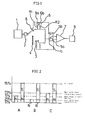
- reference numerals 1 and 2 indicate a light emitting circuit and a light emitting element for detecting smoke respectively.
- a part of the reflected light is received by a photoelectric element 3 for detecting smoke.
- the photoelectric element 3 for detecting smoke is connected to an amplifier circuit 7 via a change-over switch 5.
- the amplifier circuit 7 is connected to a switching circuit 9.
- a shield plate 4 is disposed between the light emitting element 2 for detecting smoke and the photoelectric element 3 for detecting smoke in order to prevent direct incidence of the light from the light emitting element 2 for detecting smoke upon the photoelectric element 3 for detecting smoke.
- a photoelectric element 8 for test is arranged at a position where the radiant energy from the light emitting element 2 for detecting smoke can be directly received and no influence of the external light is given.
- the photoelectric element 8 for test is connected to the amplifier circuit 7 of the above-mentioned optical system for detecting smoke via change-over switches 6 and 5.
- the change-over switch 5 comprising a relay and other parts is connected to a contact 5a. Every time when the light emitting element 2 for detecting smoke emits light (in the case of pulse light emitting system), a random reflected light (internal noise light) is generated at an inner wall surface of the labyrinth which is not shown in the drawing and the photoelectric element 3 for detecting smoke receives this internal noise light to produce a noise light output. Only this output is sent to an amplifier circuit 7. In the case of continuous light emitting system, these processes are continuously performed.
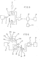
- the switching circuit 9 When smoke enters the labyrinth not shown in the drawing, a scattered light is generated by smoke and the photoelectric element 3 for detecting smoke produces an output by received light which is the sum of an output by internal noise light and an output by received said scattered light due to smoke. When this total output reaches a fire level, the switching circuit 9 is actuated to send a fire signal. This is a normal operating condition of the smoke detector. Assuming that this detector sends out a fire signal with a smoke density of 10% and that the intensity of internal noise light corresponds to a smoke density of 5%, the switching circuit 9 should be actuated to send out a fire signal in normal condtion whenever the sum of the internal noise light N and the smoke density S amounts to the fire level of 15% as shown in Fig.
- a smoke density of 5% is taken, plus or minus 2.5% of which i.e. 5 + 2.5% is the normal level range.
- the condition wherein the internal noise light reduced to smoke density is 2.5% (lower limit of normal level range) or less is the condition under which the detector fails to alarm. Additionally, the condition wherein the internal noise light reduced to smoke desnity is 7.5% (upper limit of normal level range) or more is the false alarm condition. Further, the conditon wherein / the internal noise light remains between the lower limit and the upper limit of normal level range is a normal condition. To discriminate these conditions, the non-operation test and the operation test are performed.
- the change-over switch 5 is connected to contact 5b by control signal from a receiver or a repeater not shown.
- Into the amplifier circuit 7 is fed a total output by received light of an output from the photoelectric element 3 for detecting smoke added with an output from the photoelectric element 8 for test, and the total output after being amplified is sent to the switching circuit 9.
- resistors R 1 and R 2 having different resistances are connected to contacts 6a and 6b in the change- over switch 6 composed of a relay etc. in Fig. l.
- the output of photoelectric element 8 for test can be regulated by changing over the switch 6.
- the resistance of resistor R 1 is adjusted to achieve a smoke density of 7.5 % so that the total of the output by the received internal noise light added with the output by received light from photoelectric element 8 for test may not reach the fire level even if the output by the received internal noise light is near the upper limit of normal level range.
- the resistance of resistor R 2 is adjusted to a smoke density of 12.5 % so that, when the output by received internal noise light is somewhat lower than the lower limit of normal level range, the total of said output added with the output by received light of photoelectric element 8 for test may not reach the fire level.
- a signal "normal” is sent to a receiver not shown and the like when the total output by received light is at non-operation level.
- a signal “abnormal” is sent to a receiver when the total output by received light is at operation level.
- a signal "abnormal” is sent to the receiver and the like when the total output by received light is at non-operation level, and a signal “normal” is sent when the total output is at operation level.
- the operation and non-operation tests of the smoke detector can be simply conducted by switching the change-over switches 6 and 5 with the control signal from the receiver, in order to check whether the detecting function of the detector is normal or not.
- the photoelectric element 8 for test is disposed at_any.desired position by connecting the light emitting element 2 for detecting smoke to the photoelectric element 8 for test with an optical path, such as optical fiber, as shown with dotted lines in the drawing.
- an address circuit comprising, for example, an oscillator having a specific frequency for each smoke detector to modulate the signal from the detector, it is possible to identify from which detector the signal has been initiated.
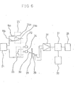
- This embodiment differs from the first embodiment in that a comparator circuit 10 is connected to an amplifier circuit 7 and, moreover, a memory circuit 11 is connected to said comparator circuit 10.
- a comparator circuit 10 is connected to an amplifier circuit 7 and, moreover, a memory circuit 11 is connected to said comparator circuit 10.
- a signal "normal” or "abnormal” is sent out on the basis of the stored result of function test when a test signal is received from a receiver not shown or the like.
- a relay 12 usually repeats "on” and “off” to open and to close a switch 13. As the switch 13 remain closed while relay 12 is "off”, the amplifier circuit 7 is fed only with an output from photoelectric element 3 for detecting smoke and fire supervision is performed.
- the amplifier circuit As the switch 13 opens when relay 12 is "on", the amplifier circuit is fed with a total output (by received light) from photoelectric element 3 for detecting smoke and from photoelectric element 8 for test and a function test is performed. The result of function test is stored in the memory circuit 11.
- the discrimination of functional conditions is made by the comparator circuit 10, which determines whether or not the output from amplifier circuit 7 has reached the lower limit of normal level range, i.e. the critical level at which the detector fails to alarm. And, a distinction is also made as to whether or not the above-mentioned output has reached the upper limit of normal level range, i.e. false alarm level.
- a test signal from a control panel which is not shown in the drawing
- the relay 12 is actuated, the switch 13 is closed, and the amplifier circuit 7 is fed with a sum of the outputs (by received light) of photoelectric element 3 for detecting smoke and of photoelectric element 8 for test.
- a normal signal is sent to the receiver if the output (by received light) just before has been in the normal level range and the all circuits are normal. If said output by received light just before is in false alarm condition, an abnormal signal such as repeated frequency different from normal signal, is sent to the receiver.
- An abnormal signal is also sent to the receiver and the like when the output (by received light) just before is at such a level that the detector fails to alarm. Further, if the light emitting element 2 stops emitting the light, for example, owing to breaking of wire and both the photoelectric element 3 for detecting smoke and the photoelectric element -8 for test do not produce the output by received light, or if the switching circuit 15 has a fault, such faults of the detector can be easily found because no signal is sent to the receiver or the like (no signal) even if the test signal is sent from the receiver and the like.
- reference numeral 15 indicate the switching circuit which is actuated to send out a fire signal when the output has reached the fire level.
- the same reference numerals in Figs. 1 and 3 indicate the same parts having the same function. In the following third embodiment of this invention will be described with reference to Fig. 4.
- reference numerals 21 and 22 indicate a light emitting circuit and a light emitting element for detecting smoke, respectively.
- the light emitting element 24 equipped with the seitch 23 is connected in series with the light emitting element 22.
- a change-over switch 25 for changing a light emission current is provided between the light emitting element 22 for detecting smoke and the light emission circuit 21.
- Light from the light emitting element 22 for detecting smoke and from the light emitting element 24 for test is received by a photoelectric element 26 which is connected to an amplifier circuit 27 connected to a switching circuit 28.
- a shield plate 29 is disposed between the light emitting element 22 for detecting smoke and the photoelectric element 26 so that the photoelectric element may not directly receive the light from light emitting element 22 for detecting smoke.
- an optical path 30, such as optical fiber, is provided so as to pass directly the light from light emitting element 24 for test to photoelectric element 26.
- the resistor Ra connected to the contact 25a of the change-over switch 25 serves as a limiting resistor or for the light emission current of light emitting element 22 for detecting smoke during the supervisory condition
- the light emitting element 24 for test does not emit light owing to closure of switch 23 and only the light emitting element 22 for detecting smoke emits light during the supervisory condition.
- the light emitted from the light emitting element 22 is scattered by smoke.
- the output by received internal noise light from photoelectric element 26 for detecting smoke is added to the output by received smoke-scattered light to produce a total output.
- the switching circuit 28 is actuated to produce a fire signal.
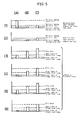
- the light emitting element 22 for detecting smoke is emitting a radiant energy as shown by (A) of (1) in Fig. 5 by a light emission current fed through resistor Ra.
- the photoelectric element 26 for detecting smoke produces an output as shown by (A) of (3) and (4) in Fig. 5, provided that the function is normal and so the intensity of internal noise light is in the normal level range.
- the output from photoelectric element 26 for detecting smoke becomes high as shown by (A) of (5) in Fig. 5.
- the output from the photoelectric element becomes low as shown by (A) of (5) in Fig. 5.'
- the switch 23 When the switch 23 is opened with control signal from a receiver not shown or the like, the light emitting element 24 for test as well as the light emitting element 22 for detecting smoke emit light.
- the light emitted by light emitting element 24 for test is received by photoelectric element 26 for detecting smoke through the optical path 30, and the total output is fed to the amplifier circuit 27 and, after amplified, is sent to the switching circuit 28.
- resistors Rb and Rc having different resistances are connected to contacts 25b and 25c of the change-over switch 25 comprising a relay etc., respectively.
- the light emission current is controlled by switching the change-over switch 25 to a proper contact.
- the resistor Rb is set so that the output during testing may not reach fire level even if the output from the photoelectric element 26 for detecting smoke during the supervisory condition is near the upper limit of normal level range, as shown by (A) of (3) in Fig. 5, and that the output by received light during testing can reach fire level when the output during the supervisory condition somewhat surpasses the upper limit of normal level range, as shown by (A) of (5) in Fig. 5.
- the resistor Rc is set so that the output during testing may reach fire level even if the output from the photoelectric element 26 for detecting smoke during the supervisory condition is near the lower limit of normal level range, as shown by (A) of (4) in Fig. 5, and that the output during testing cannot reach fire level when the output during the supervisory condition is somewhat lower than the lower limit of normal level range as shown by (A) of (6) in Fig. 5.
- the change-over switch 25 is connected to the contact 25b and a light emission current is fed to the light emitting element 22 for detecting smoke and the light emitting element 24 for test through the resistor Rb.
- the light emitting element 22 for detecting smoke emits light in radiation as shown by (B) of (1) in Fig. 5 and the light emitting element 24 for test emits light in radiation as shown by (B) of (2) in Fig. 5.
- the photoelectric element 26 for detecting smoke receives a direct light from the light emitting element 24 for test and a scattered light from wall surface which arise from light emitted by the light emitting element 22 for detecting smoke.
- the photoelectric element 26 for detecting smoke produces an outputs as shown by (B) of (3) or (4) in Fig. 5.
- the element 26 produces an output by received light as shown by (B) of (5) in Fig. 5, if the internal noise light is too intense.
- the element 26 produces an output as shown by (B) of (6) in Fig. 5, if the light-receiving surface of photoelectric element 26 for detecting smoke is soiled.
- the change-over switch 25 is connected to contact 25b and contact 25c, and a light emission current is fed to the light emitting element 22 for detecting smoke and the light emitting element 24 for test through resistor Rb and resistor Rc.
- the light emitting element 22 for detecting smoke emits light in radiation as shown by (C) of (1) in Fig. 5 and the light emitting element 24 for test emits light in a radiation as shown by (C) of (2) in Fig. 5.
- the photoelectric element 26 for detecting smoke receives the light from both light emitting elements 22 and 24 and produces an output as shown by (C) of (3) or (4) in Fig. 5, when the function is normal.
- the element 26 produces an output as shown by (C) of (5) in Fig. 5, if the internal noise light is too intense.
- the element 26 produces an output by received light as shown by (C) of (6) in Fig. 5, if its light-receiving suface is soiled.
- a signal "normal” is sent to a receiver not shown or the like when the total output is at non-operation level, and a signal “abnormal” is sent when the total output is at operation level.
- a signal "abnormal” is sent to a receiver when the total output is at non-operation level, and a signal “normal” is sent when the total output is at operation level.
- the operation and non-operation tests of the smoke detector are simply conducted by switching the switch 23 and the change-over switch 25 with a control signal from the receiver, in order to check whether the detecting function of the detector is normal or not.
- alarm failure condition and false alarm condition they are the same as described in the first embodiment.
- This embodiment differs from the third embodiment in that a comparator circuit 31 is connected to an amplifier circuit 27 and, in addition, a memory circuit 32 is connected to said comparator circuit 31.
- a comparator circuit 31 is connected to an amplifier circuit 27 and, in addition, a memory circuit 32 is connected to said comparator circuit 31.
- a comparator circuit 31 is connected to an amplifier circuit 27 and, in addition, a memory circuit 32 is connected to said comparator circuit 31.
- a comparator circuit 31 is connected to an amplifier circuit 27 and, in addition, a memory circuit 32 is connected to said comparator circuit 31.
- a comparator circuit 31 is connected to an amplifier circuit 27 and, in addition, a memory circuit 32 is connected to said comparator circuit 31.
- a relay not shown repeats "on” and “off” to open and close a switch 23. While the relay is “off” the change-over switch 25 is connected to contact 25a and a large current I i as light emission current flows through the resistor Ra. As the switch 23 is closed at this time, the light emitting element 24 for test is short-circuited and the light emission current I 1 flows only through the light emitting element 22 for detecting smoke to emit light in a large radiant energy. The noise light arising from this light is received by the photoelectric element 26 for detecting smoke and the output by received light therefrom is fed to the amplifier circuit 27.
- the switch 23 When the relay becomes "on", the switch 23 is opened to release the sort-circuit of the light emitting element 24 for test, and simultaneously the change-over switch 25 is connected to contact 25b.
- a small current 1 2 as light emission current is fed to the light emitting element 22 for detecting smoke and the light emitting element 24 for test through the resistor Rb. Due to this light emission current I 2 , the light emitting element 22 for detecting smoke and the light emitting element 24 for test emits light in a small radiation.
- the photoelectric element 26 for detecting smoke receives the noise light arising from light emitted by light emitting element 22 for detecting smoke and a direct light from light emitting element 24 for test, and feeds the total outputs to the amplifier 27.
- reference numerals 21, 28, 29 and 30 indicate a light emission circuit, a switching circuit, a shield plate and an optical path such as optical fiber, respectively.
- the light emitting element 24 and photoelectric element 26 may be arranged in such a way that they face each other so that the light is directly led to the photoelectric element 26 without passing through optical path 29.
- the means according to this invention comprises an optical system for detecting smoke, an optical system for test, and a circuit for measuring a total output of an output by received light from said optical system for detecting smoke added with an output from said optical system for test, it is not necessary to remove the smoke detector from the ceiling or to apply smoke to the detector for testing. Thus, one person can test the functions of the smoke detector from the receiver etc. Moreover, the light-receiving surface of the photoelectric element is not soiled because no smoke is used.
- Figs. 1, 3, 4, and 6 represent block diagrams of various embodiments according to this invention.
- Fig. 2 shows the relation between the smoke density and fire level etc. in the embodiment of Fig. 1.
- Fig. 5 illustrates the relation among the radiant energy of light emitting element, the output by received light from photoelectric element, and fire level in the embodiment of Fig. 4.
Landscapes
- Engineering & Computer Science (AREA)
- Computer Security & Cryptography (AREA)
- Physics & Mathematics (AREA)
- General Physics & Mathematics (AREA)
- Fire-Detection Mechanisms (AREA)
- Investigating Or Analysing Materials By Optical Means (AREA)
Applications Claiming Priority (2)
| Application Number | Priority Date | Filing Date | Title |
|---|---|---|---|
| JP218918/82 | 1982-12-14 | ||
| JP21891882A JPS59108940A (ja) | 1982-12-14 | 1982-12-14 | 散乱光式煙感知器の機能試験装置 |
Publications (3)
| Publication Number | Publication Date |
|---|---|
| EP0113461A2 true EP0113461A2 (fr) | 1984-07-18 |
| EP0113461A3 EP0113461A3 (en) | 1986-10-01 |
| EP0113461B1 EP0113461B1 (fr) | 1989-08-02 |
Family
ID=16727355
Family Applications (1)
| Application Number | Title | Priority Date | Filing Date |
|---|---|---|---|
| EP19830112561 Expired EP0113461B1 (fr) | 1982-12-14 | 1983-12-14 | Moyens fonctionnels de test pour un détecteur de fumée du type à dispersion de lumière |
Country Status (3)
| Country | Link |
|---|---|
| EP (1) | EP0113461B1 (fr) |
| JP (1) | JPS59108940A (fr) |
| DE (1) | DE3380327D1 (fr) |
Cited By (3)
| Publication number | Priority date | Publication date | Assignee | Title |
|---|---|---|---|---|
| DE3614140A1 (de) * | 1985-04-26 | 1986-11-06 | Hochiki K.K., Tokio/Tokyo | Ausgabekorrektureinrichtung fuer einen analogsensor |
| EP0755037A1 (fr) * | 1995-07-20 | 1997-01-22 | HOCHIKI Kabushiki Kaisha | Détecteur de fumée photoélectrique et système de prévention de sinistres utilisant celui-ci |
| DE19912911A1 (de) * | 1999-03-22 | 2000-10-19 | Schako Metallwarenfabrik | Vorrichtung zur Erkennung von Rauch |
Families Citing this family (4)
| Publication number | Priority date | Publication date | Assignee | Title |
|---|---|---|---|---|
| EP0248957A1 (fr) * | 1986-06-12 | 1987-12-16 | Pittway Corporation | Détecteur auto-testant pour produits de combustion |
| JPH023891A (ja) * | 1988-06-16 | 1990-01-09 | Nohmi Bosai Ltd | 火災警報装置における汚れ補正方法とその装置 |
| JP2549442B2 (ja) * | 1989-08-12 | 1996-10-30 | 松下電工株式会社 | 光電式煙感知器 |
| GB2273769B (en) * | 1992-12-15 | 1996-08-28 | Stephen Henry Ellwood | Proportional light scattering sensor |
Citations (5)
| Publication number | Priority date | Publication date | Assignee | Title |
|---|---|---|---|---|
| US2627064A (en) * | 1950-07-15 | 1953-01-27 | C O Two Fire Equipment Co | Smoke detector testing means |
| GB949651A (en) * | 1961-12-27 | 1964-02-19 | Pyrene Co Ltd | Improvements in or relating to photo-electric indicator circuits |
| DE1277710B (de) * | 1965-07-26 | 1968-09-12 | Honeywell Inc | Selbstpruefende Einrichtung mit einem Zustandsfuehler |
| US4053785A (en) * | 1976-01-07 | 1977-10-11 | General Signal Corporation | Optical smoke detector with smoke effect simulating means |
| US4232307A (en) * | 1978-12-18 | 1980-11-04 | American District Telegraph Company | Electrical test circuit for optical particle detector |
Family Cites Families (3)
| Publication number | Priority date | Publication date | Assignee | Title |
|---|---|---|---|---|
| JPS5526515B2 (fr) * | 1974-03-04 | 1980-07-14 | ||
| JPS5397481A (en) * | 1977-02-05 | 1978-08-25 | Kokusai Gijutsu Kaihatsu Kk | Smoke detector |
| JPS56100342A (en) * | 1980-01-14 | 1981-08-12 | Matsushita Electric Works Ltd | Photoelectric type smoke sensor |
-
1982
- 1982-12-14 JP JP21891882A patent/JPS59108940A/ja active Granted
-
1983
- 1983-12-14 DE DE8383112561T patent/DE3380327D1/de not_active Expired
- 1983-12-14 EP EP19830112561 patent/EP0113461B1/fr not_active Expired
Patent Citations (5)
| Publication number | Priority date | Publication date | Assignee | Title |
|---|---|---|---|---|
| US2627064A (en) * | 1950-07-15 | 1953-01-27 | C O Two Fire Equipment Co | Smoke detector testing means |
| GB949651A (en) * | 1961-12-27 | 1964-02-19 | Pyrene Co Ltd | Improvements in or relating to photo-electric indicator circuits |
| DE1277710B (de) * | 1965-07-26 | 1968-09-12 | Honeywell Inc | Selbstpruefende Einrichtung mit einem Zustandsfuehler |
| US4053785A (en) * | 1976-01-07 | 1977-10-11 | General Signal Corporation | Optical smoke detector with smoke effect simulating means |
| US4232307A (en) * | 1978-12-18 | 1980-11-04 | American District Telegraph Company | Electrical test circuit for optical particle detector |
Cited By (4)
| Publication number | Priority date | Publication date | Assignee | Title |
|---|---|---|---|---|
| DE3614140A1 (de) * | 1985-04-26 | 1986-11-06 | Hochiki K.K., Tokio/Tokyo | Ausgabekorrektureinrichtung fuer einen analogsensor |
| EP0755037A1 (fr) * | 1995-07-20 | 1997-01-22 | HOCHIKI Kabushiki Kaisha | Détecteur de fumée photoélectrique et système de prévention de sinistres utilisant celui-ci |
| DE19912911A1 (de) * | 1999-03-22 | 2000-10-19 | Schako Metallwarenfabrik | Vorrichtung zur Erkennung von Rauch |
| DE19912911C2 (de) * | 1999-03-22 | 2001-07-19 | Schako Metallwarenfabrik | Vorrichtung zur Erkennung von Rauch |
Also Published As
| Publication number | Publication date |
|---|---|
| JPS648783B2 (fr) | 1989-02-15 |
| EP0113461B1 (fr) | 1989-08-02 |
| JPS59108940A (ja) | 1984-06-23 |
| EP0113461A3 (en) | 1986-10-01 |
| DE3380327D1 (en) | 1989-09-07 |
Similar Documents
| Publication | Publication Date | Title |
|---|---|---|
| EP0122489A1 (fr) | Dispositif pour tester le fonctionnement d'un détecteur de fumée photo-électrique | |
| US4769550A (en) | Dual scattering-type smoke detector with cross-checking | |
| JPS59168599A (ja) | 警報設備に設けられている報知器の障害レベル監視用回路装置 | |
| EP0113461A2 (fr) | Moyens fonctionnels de test pour un détecteur de fumée du type à dispersion de lumière | |
| JPH0430699B2 (fr) | ||
| EP0047421B1 (fr) | Détection de défaut pour un détecteur de flamme | |
| US4199755A (en) | Optical smoke detector | |
| US4308531A (en) | Light transmission type smoke detector | |
| CA1051539A (fr) | Circuit detecteur de fumee avec del | |
| JPH07200961A (ja) | 火災の早期検出用火災警報装置 | |
| EP0122432B1 (fr) | Détecteur de fumée photoélectrique équipé avec un essai de fonctionnement de la détection de fumée | |
| JPS59210347A (ja) | 散乱光式煙感知器の機能試験装置 | |
| GB2043977A (en) | Detector for detecting smoke or fire | |
| JPS6022477Y2 (ja) | 失報防止回路付き煙感知器 | |
| EP0113046A2 (fr) | Détecteur de chaleur | |
| JPH0695358B2 (ja) | 散乱光式煙感知器の機能試験装置 | |
| JPH0695360B2 (ja) | 散乱光式煙感知器の機能試験装置 | |
| JPH02230396A (ja) | 散乱光式煙感知器の機能試験装置 | |
| JPS646408B2 (fr) | ||
| KR20240040299A (ko) | 비화재보 감소를 위한 p형 수신기 기반 최적화된 아날로그감지기 형식의 자동화재경보 시스템 | |
| JPH0695359B2 (ja) | 散乱光式煙感知器の機能試験装置 | |
| JPS5894095A (ja) | 光電式煙感知器 | |
| JPH0285994A (ja) | 光電式煙感知器の機能検査装置 | |
| JPS5946840A (ja) | 試験機能付光電式煙感知器 | |
| JPS59210346A (ja) | 散乱光式煙感知器の機能試験装置 |
Legal Events
| Date | Code | Title | Description |
|---|---|---|---|
| PUAI | Public reference made under article 153(3) epc to a published international application that has entered the european phase |
Free format text: ORIGINAL CODE: 0009012 |
|
| 17P | Request for examination filed |
Effective date: 19831214 |
|
| AK | Designated contracting states |
Designated state(s): CH DE FR GB LI NL |
|
| PUAL | Search report despatched |
Free format text: ORIGINAL CODE: 0009013 |
|
| AK | Designated contracting states |
Kind code of ref document: A3 Designated state(s): CH DE FR GB LI NL |
|
| 17Q | First examination report despatched |
Effective date: 19870909 |
|
| GRAA | (expected) grant |
Free format text: ORIGINAL CODE: 0009210 |
|
| AK | Designated contracting states |
Kind code of ref document: B1 Designated state(s): CH DE FR GB LI NL |
|
| REF | Corresponds to: |
Ref document number: 3380327 Country of ref document: DE Date of ref document: 19890907 |
|
| ET | Fr: translation filed | ||
| PLBE | No opposition filed within time limit |
Free format text: ORIGINAL CODE: 0009261 |
|
| STAA | Information on the status of an ep patent application or granted ep patent |
Free format text: STATUS: NO OPPOSITION FILED WITHIN TIME LIMIT |
|
| 26N | No opposition filed | ||
| REG | Reference to a national code |
Ref country code: CH Ref legal event code: PFA Free format text: NOHMI BOSAI LTD |
|
| PGFP | Annual fee paid to national office [announced via postgrant information from national office to epo] |
Ref country code: NL Payment date: 19941231 Year of fee payment: 12 |
|
| PG25 | Lapsed in a contracting state [announced via postgrant information from national office to epo] |
Ref country code: NL Effective date: 19960701 |
|
| NLV4 | Nl: lapsed or anulled due to non-payment of the annual fee |
Effective date: 19960701 |
|
| PGFP | Annual fee paid to national office [announced via postgrant information from national office to epo] |
Ref country code: FR Payment date: 19971208 Year of fee payment: 15 |
|
| PGFP | Annual fee paid to national office [announced via postgrant information from national office to epo] |
Ref country code: GB Payment date: 19971218 Year of fee payment: 15 |
|
| PGFP | Annual fee paid to national office [announced via postgrant information from national office to epo] |
Ref country code: DE Payment date: 19971222 Year of fee payment: 15 |
|
| PGFP | Annual fee paid to national office [announced via postgrant information from national office to epo] |
Ref country code: CH Payment date: 19980116 Year of fee payment: 15 |
|
| PG25 | Lapsed in a contracting state [announced via postgrant information from national office to epo] |
Ref country code: GB Free format text: LAPSE BECAUSE OF NON-PAYMENT OF DUE FEES Effective date: 19981214 |
|
| PG25 | Lapsed in a contracting state [announced via postgrant information from national office to epo] |
Ref country code: LI Free format text: LAPSE BECAUSE OF NON-PAYMENT OF DUE FEES Effective date: 19981231 Ref country code: CH Free format text: LAPSE BECAUSE OF NON-PAYMENT OF DUE FEES Effective date: 19981231 |
|
| GBPC | Gb: european patent ceased through non-payment of renewal fee |
Effective date: 19981214 |
|
| REG | Reference to a national code |
Ref country code: CH Ref legal event code: PL |
|
| PG25 | Lapsed in a contracting state [announced via postgrant information from national office to epo] |
Ref country code: FR Free format text: LAPSE BECAUSE OF NON-PAYMENT OF DUE FEES Effective date: 19990831 |
|
| REG | Reference to a national code |
Ref country code: FR Ref legal event code: ST |
|
| PG25 | Lapsed in a contracting state [announced via postgrant information from national office to epo] |
Ref country code: DE Free format text: LAPSE BECAUSE OF NON-PAYMENT OF DUE FEES Effective date: 19991001 |