EP0112979A2 - Appareil d'aide respiratoire - Google Patents
Appareil d'aide respiratoire Download PDFInfo
- Publication number
- EP0112979A2 EP0112979A2 EP83109830A EP83109830A EP0112979A2 EP 0112979 A2 EP0112979 A2 EP 0112979A2 EP 83109830 A EP83109830 A EP 83109830A EP 83109830 A EP83109830 A EP 83109830A EP 0112979 A2 EP0112979 A2 EP 0112979A2
- Authority
- EP
- European Patent Office
- Prior art keywords
- valve
- pressure
- branch
- inspiratory
- peep
- Prior art date
- Legal status (The legal status is an assumption and is not a legal conclusion. Google has not performed a legal analysis and makes no representation as to the accuracy of the status listed.)
- Granted
Links
Images
Classifications
-
- A—HUMAN NECESSITIES
- A61—MEDICAL OR VETERINARY SCIENCE; HYGIENE
- A61M—DEVICES FOR INTRODUCING MEDIA INTO, OR ONTO, THE BODY; DEVICES FOR TRANSDUCING BODY MEDIA OR FOR TAKING MEDIA FROM THE BODY; DEVICES FOR PRODUCING OR ENDING SLEEP OR STUPOR
- A61M16/00—Devices for influencing the respiratory system of patients by gas treatment, e.g. mouth-to-mouth respiration; Tracheal tubes
- A61M16/20—Valves specially adapted to medical respiratory devices
- A61M16/201—Controlled valves
- A61M16/206—Capsule valves, e.g. mushroom, membrane valves
-
- A—HUMAN NECESSITIES
- A61—MEDICAL OR VETERINARY SCIENCE; HYGIENE
- A61M—DEVICES FOR INTRODUCING MEDIA INTO, OR ONTO, THE BODY; DEVICES FOR TRANSDUCING BODY MEDIA OR FOR TAKING MEDIA FROM THE BODY; DEVICES FOR PRODUCING OR ENDING SLEEP OR STUPOR
- A61M16/00—Devices for influencing the respiratory system of patients by gas treatment, e.g. mouth-to-mouth respiration; Tracheal tubes
- A61M16/20—Valves specially adapted to medical respiratory devices
- A61M16/208—Non-controlled one-way valves, e.g. exhalation, check, pop-off non-rebreathing valves
- A61M16/209—Relief valves
-
- A—HUMAN NECESSITIES
- A61—MEDICAL OR VETERINARY SCIENCE; HYGIENE
- A61M—DEVICES FOR INTRODUCING MEDIA INTO, OR ONTO, THE BODY; DEVICES FOR TRANSDUCING BODY MEDIA OR FOR TAKING MEDIA FROM THE BODY; DEVICES FOR PRODUCING OR ENDING SLEEP OR STUPOR
- A61M16/00—Devices for influencing the respiratory system of patients by gas treatment, e.g. mouth-to-mouth respiration; Tracheal tubes
- A61M16/0057—Pumps therefor
- A61M16/0075—Bellows-type
-
- A—HUMAN NECESSITIES
- A61—MEDICAL OR VETERINARY SCIENCE; HYGIENE
- A61M—DEVICES FOR INTRODUCING MEDIA INTO, OR ONTO, THE BODY; DEVICES FOR TRANSDUCING BODY MEDIA OR FOR TAKING MEDIA FROM THE BODY; DEVICES FOR PRODUCING OR ENDING SLEEP OR STUPOR
- A61M16/00—Devices for influencing the respiratory system of patients by gas treatment, e.g. mouth-to-mouth respiration; Tracheal tubes
- A61M16/0003—Accessories therefor, e.g. sensors, vibrators, negative pressure
- A61M2016/003—Accessories therefor, e.g. sensors, vibrators, negative pressure with a flowmeter
Definitions
- the invention relates to a breathing apparatus (respirator) for restoring the spontaneous breathing of patients, with an inspiratory and an expiratory branch, a continuously positive airway pressure (CPAP) being adjustable to a peep level by means of an overflow valve or the like (peep valve).
- a breathing apparatus for restoring the spontaneous breathing of patients, with an inspiratory and an expiratory branch, a continuously positive airway pressure (CPAP) being adjustable to a peep level by means of an overflow valve or the like (peep valve).
- CPAP continuously positive airway pressure
- CPAP breathing i.e. H. breathing under continuously positive airway pressure
- either heavy breathing machines that have this type of ventilation or special CPAP devices are used.
- the generation and securing of the permanent positive pressure level in the entire respiratory tract takes place in the known devices according to two principles, namely the high flow CPAP or the demand CPAP.
- High-flow CPAP the patient is offered a constant gas flow.
- the desired pressure in the respiratory tract is determined by a pressure relief valve, e.g. B. by the immersion depth of an expiration tube in a water castle.
- High-flow CPAP devices are inexpensive, but they have a number of design-related disadvantages.
- the large expiratory airway resistances i.e. H.
- peep level the desired pressure level set on the device
- the high-flow CPAP device therefore causes a constant gas flow under a positive pressure level of 5 - 1C mbar.
- the patient therefore has a constant gas flow a patient connection tee is available. Since the gas consumption must be adjusted to the highest possible withdrawal of the patient, a high gas consumption results from the fact that the gas flows out of the overflow valve (peep valve) unused in the expiration phase.
- the high airway resistance in the expiration phase results from the fact that, in addition to the constant gas flow, the exhaled air is added, so that there is an increase in pressure in the expiratory airway.
- peep valve overflow valve
- the expiratory branch absorbs both the constant gas flow and the exhaled air during the exhalation phase, it is not possible or only insufficiently possible to measure the respiratory volume via a differential measurement, whereby gas losses in the system should be taken into account.
- the measurement of the breathing volume is of great importance for the determination of the oxygen content in the blood.
- the inspiratory gas flow desired by the patient is controlled by a pressure sensor and a adjustable inspiration valve offered according to need.
- the disadvantages of high-flow CPAP are partially avoided, since only the desired tidal volume can be delivered and the existing monitoring systems can be used.
- the required measuring and switching times of the pressure sensor and the inspiration valve have a disadvantageous effect, ie the patient does not initially receive the breathing gas or delivers it in small quantities and later in batches or in too large quantities.
- the additionally required expiration valves also have considerable flow resistances or limit the flow rate of the expiration air due to insufficient opening angles.
- the airway pressure is measured by a pressure transducer on the expiration side.
- the signal from the converter is compared with the specified peep level. A difference between the actual and the set value results in a signal to the expiration valve.
- the expiration valve constantly corrects this signal so that the desired peep level is obtained.
- the invention has for its object to provide an inexpensive breathing aid device of the initially described type, which has a very low airway resistance in the expiratory phase, which enables a delay-free and thus "soft * coupling between the patient and the device in the inspiratory phase, and in which the breathing air pressure when inspiring and expiring only slightly and in a defined size undershoots or overshoots the required pressure level, ie causes the patient load to be as low as possible.
- Another essential task is to make it possible to measure the respiratory volume.
- Another task is to make the breathing apparatus according to the invention such train that a lower constant gas flow than in known devices constantly is offered and demand peaks are additionally fed into the system (low-flow CPAP system).
- the object of the invention is also to increase the possibility of using the device.
- the invention therefore combines the advantages of both known systems without having to accept the main disadvantages.
- the constructive embodiment of the device according to the invention also represents a combination of the known systems, but with the essential difference that the valve for adjusting the pressure level (peep valve) is no longer arranged in the expiration branch as in the high-flow CPAP system, but in the inspiration branch and that the expiration valve according to the invention only has an open / close function.
- the measurement in the expiration branch is also important insofar as such devices have a certain leak rate, ie when measuring the passage volume in the inspiration branch it is not possible to see to what extent leak losses will still occur here.
- the expiration valve located at the end of the inspiration branch only has an open / close function, ie above the set pressure level (peep level) the exhaled air can pass through the valve. It can therefore also be designed as a known peep valve.
- the inspiratory branch of the breathing apparatus is made from a single-use disposable branch during the expiratory phase valve or check valve, in particular separated by a mica valve known per se.
- This valve is set such that it closes when the pressure in the expiratory branch is above the peep level, caused by the patient's exhalation process.
- the one-way valve is placed as close as possible to the patient connection in order to close off the entire inspiratory branch as much as possible during the expiration phase, or to keep the pressure loss and thus the airway resistance in the inspiratory branch as low as possible.
- a standpipe with a water lock has proven itself as a simple peep valve, the pressure level of which can be adjusted from 5 to 10 mbar. In certain applications, however, lower or higher pressures are also necessary.
- an advantageous design of the expiration valve is provided, it being necessary to ensure that the minimum pressure level must be maintained during exhalation (expiration phase), ie. H. exhale against the pressure of the peep level.
- This can either be a simple peep valve itself or a pressure valve controlled by the inspiratory branch.
- a controllable expiration valve is a more complex and time-delayed method.
- the invention works in a preferred embodiment according to a low-flow CPAP principle, ie a lower gas quantity is selected as the constant gas flow.
- the invention provides an additional pressure stabilizer, the gas of which is added to the inspiratory branch if necessary.
- a high-pressure gas mixer is provided, which already fills the bellows of the pressure stabilizer with gas during emptying and the expiratory phase.
- a throttle device lowers the pressure of the high-pressure gas mixer to the pressure in the inspiratory branch, ie to the peep level.
- This throttle device can be designed as a flow meter with an adjustment valve for reducing the pressure.
- the pressure in the pressure stabilizer can be slightly above the pressure of the Peep-Niüeau.
- the measures according to the invention accordingly combine the advantages of the known devices without their disadvantages - apart from low gas consumption - being accepted.
- the device according to the invention is so simple that it can compete in price with the high-flow CPAP device, but does not have its disadvantages, especially in the expiratory branch.
- the device delivers the volume required by the patient at the set airway pressure. If the patient has met his needs, no complex regulation is required, since the one-way valve separates the inspiratory branch and the expiration can take place. During this time, the continuously supplied gas escapes via the peep valve without the need to regulate or control an inspiration valve. The patient always has the option of increasing the breathing volume as desired through self-breathing.
- the invention is also suitable without the setting of a constant positive airway pressure (CPAP), or an airway pressure that could almost be described as normal pressure. This can be done either by adjusting the peep valve itself or without any special valve.
- CPAP constant positive airway pressure
- this can also advantageously be used as a respirator ("flow chopper") by connecting an open / close valve controlled by a time-clock circuit to the peep valve.
- flow chopper By closing or regulating the valve, additional ventilation in a wide variety of forms can take place.
- An additional overpressure safety valve serves the Sichor of the patient in the event of device or valve malfunctions.
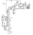
- An advantageous exemplary embodiment is shown in FIG. 1 and described in more detail below.
- the figure shows a schematic representation of the construction of the breathing apparatus according to the invention.
- the breathing apparatus 10 for connection to a patient 11 consists of an inspiratory branch 12 and an expiratory branch 13. Between these two branches, a patient connection tee 14 is provided, i. a. via a connection by means of a patient hose system 44.
- the desired gas mixture - normally room air enriched with oxygen - is supplied from a high-pressure gas mixer 15 into the inspiration channel 16 of the inspiration branch 12.
- the gas supplied by the high-pressure gas mixer at approx. 5 bar is reduced to a lower pressure via a rotameter 17 with a throttle valve.
- a pressure is set by a so-called peep valve 18 in the inspiration branch 12, which is approximately 5-10 mbar above normal pressure.
- a one-way valve 19 is also provided in the inspiration branch 12 in the area of the inspiration outlet.
- the inspiration branch 12 consists of a direct supply part with the inspiration channel 16 and a memory 20.
- the memory 20 consists of a pressure stabilizer 21 d. H.
- a bellows 23 under spring pressure This bellows 23 is filled by the high-pressure gas mixer 15 via the line 24 and a level control valve 25.
- two drive variants for the bellows 23 are shown, with the aid of which the bellows can be pressed together and the pressure stabilizer can be emptied.
- a hydraulic or pneumatic drive unit consisting of a working cylinder 26 with a drive piston, is provided for this purpose.
- the drive can also have an electric drive 27, for. B. a stepper motor or linear motor.
- the springs 22 serve to reset the bellows 23.
- the pressure in the bellows corresponds approximately to the peep level, but is expediently set about 5 mbar higher.
- the bellows are emptied via a line 28 and a controllable valve 29.
- the expiratory branch 13 consists of an expiratory channel 30 at the end of which an expiration valve 31 connects, which can be designed as a peep valve known per se.
- the expiration valve 31 only has the function open / closed. In order to maintain the continuously positive airway pressure (CPAP), however, it must close to a certain pressure level (peep level). This can be achieved in a simple manner in that the inspiratory channel 16 is connected to a pneumatic device 33 of the expiration valve 31 via a pressure line 32.
- the pressure in line 16 acts on a piston 34, the piston rod of which rests on a sealing plate 35 acts, which seals the outlet of the expiratory channel 30 similar to a valve seal.
- the expiration valve 31 also has a breathing gas outlet 36.
- the expiration channel 30 has a number of measuring devices. These are in particular a pressure sensor 37 with a measuring amplifier 38 which is connected via a line 39 to the solenoid valve 29 of the pressure stabilizer device 21. Furthermore, a pressure display 40 and a. Flow meter 41 each provided with an alarm indicator.
- a controllable on / off valve 42 additionally connected downstream of the peep valve 18 enables the above-described expansion of the device as a respirator (flow chopper).
- a safety valve 43 in the inspiration branch prevents an event. overpressure in the event of incorrect control of valve 42 or other units.
- peep valve 18 Due to the arrangement of the peep valve 18 in the inspiration branch 12, only the gas which is directly required reaches the patient 11. The rest flows out via the peep valve (overflow valve) 18, whereby the set pressure level (peep level) is simultaneously reached and the solenoid valve 29 is closed again.
- the patient 11 During the subsequent expiration, the patient 11 generates an overpressure in the system which is dependent on the flow resistance and the expiration gas velocity, as a result of which the one-way valve 19 is closed and the expiration valve 31 is opened.
- the expired air then reaches the expiration valve 31 via the measuring devices 40, 41 and from there via the outlet 36 to the surroundings.
- Due to the pneumatic device 33 - 35 arranged in the expiration valve 31, the pressure prevailing in the expiration channel 30 must be greater than the set peep level so that the expiration air can leave the outlet 36 of the expiration valve 31.
- the patient is therefore constantly under the positive airway pressure (CPAP) set by the peep level.
- CPAP positive airway pressure
- the system of the pressure stabilizer 21 is refilled and the gas flow set on the rotameter 17 is discharged via the peep valve.
- the overpressure generated by the patient in the system slowly drops until the pressure set on the valve 18 level the expiration valve 31 closes again.
- the fluctuation range of the airway pressure around the peep level which is approx. 5 - 10 mbar, d. H. the undershoot and overshoot ranges around the set pressure level amount to a maximum of 3 mbar with the device according to the invention.
- This effect results from the soft coupling of the device to the patient and a set low flow, i. H. a constant minimum amount of gas, as well as a fast response time and gas supply to the pressure control device 21.
- the peep valve is no longer located at the end of the expiration branch, but in the inspiration branch, so that the expiration branch only absorbs exhaled air from the patient got to. This enables lower respiratory pressure ratios or pressure fluctuations and precise measurement of the respiratory volume.
- the invention is not restricted to the exemplary embodiment shown and described. It also includes all professional modifications and further training as well as partial and / or sub-combination of the features and measures described and / or shown.
Applications Claiming Priority (2)
| Application Number | Priority Date | Filing Date | Title |
|---|---|---|---|
| DE3240897 | 1982-11-05 | ||
| DE19823240897 DE3240897A1 (de) | 1982-11-05 | 1982-11-05 | Atemhilfegeraet |
Publications (3)
| Publication Number | Publication Date |
|---|---|
| EP0112979A2 true EP0112979A2 (fr) | 1984-07-11 |
| EP0112979A3 EP0112979A3 (en) | 1984-09-26 |
| EP0112979B1 EP0112979B1 (fr) | 1987-02-04 |
Family
ID=6177383
Family Applications (1)
| Application Number | Title | Priority Date | Filing Date |
|---|---|---|---|
| EP83109830A Expired EP0112979B1 (fr) | 1982-11-05 | 1983-10-01 | Appareil d'aide respiratoire |
Country Status (2)
| Country | Link |
|---|---|
| EP (1) | EP0112979B1 (fr) |
| DE (2) | DE3240897A1 (fr) |
Cited By (6)
| Publication number | Priority date | Publication date | Assignee | Title |
|---|---|---|---|---|
| WO1991012033A1 (fr) * | 1990-02-07 | 1991-08-22 | Flow-Meter S.P.A. | Recipient de recuperation et de conservation de liquides |
| US5520172A (en) * | 1992-04-16 | 1996-05-28 | Obermayer; Anton | Anesthetic machine |
| EP0917883A1 (fr) * | 1997-11-20 | 1999-05-26 | Siemens-Elema AB | Générateur de pression du gaz pour un ventilateur |
| EP1230942A2 (fr) * | 2001-02-07 | 2002-08-14 | Siemens-Elema AB | Récipient de gaz |
| EP1898979A2 (fr) * | 2005-07-04 | 2008-03-19 | Lifevent Medical Limited | Dispositif de pression positive continue des voies aeriennes |
| US10589042B2 (en) | 2011-11-11 | 2020-03-17 | ResMed Pty Ltd | Exchanger assembly for respiratory treatment |
Families Citing this family (6)
| Publication number | Priority date | Publication date | Assignee | Title |
|---|---|---|---|---|
| DE3712389C2 (de) * | 1987-04-11 | 2000-01-05 | Anton Obermayer | Atemhilfegerät |
| DE3712388A1 (de) * | 1987-04-11 | 1988-10-27 | Obermayer Anton | Atemhilfegeraet |
| DE3820043C2 (de) * | 1987-11-20 | 1999-10-28 | Anton Obermayer | Atemhilfegerät |
| EP0346527B1 (fr) * | 1988-06-13 | 1993-03-03 | Anton Dr.-Ing. Obermayer | Respirateur |
| DE102007014465A1 (de) * | 2006-04-01 | 2007-12-06 | Weinmann Geräte für Medizin GmbH & Co. KG | Peep-Ansteuerung |
| DE102015105677B4 (de) * | 2015-04-14 | 2021-12-09 | Hunger Maschinen Gmbh | Hydraulische Schmiedepresse mit einem Regulierventil zur Füllstandsregulierung |
Citations (7)
| Publication number | Priority date | Publication date | Assignee | Title |
|---|---|---|---|---|
| US2584450A (en) * | 1947-09-02 | 1952-02-05 | Univ Minnesota | Tracheotomy inhaler apparatus |
| DE1912572A1 (de) * | 1968-03-18 | 1970-03-19 | Veriflo Corp | Verfahren und Einrichtung zum Erzeugen und Abgeben eines Gemisches aus zwei Gasen unter Einhaltung eines einstellbaren Mischungsverhaeltnisses |
| US4082093A (en) * | 1977-04-27 | 1978-04-04 | Bourns, Inc. | Compensator valve |
| GB2012172A (en) * | 1978-01-14 | 1979-07-25 | Draegerwerk Ag | Respiratory control equipment and respiratory apparatus |
| DE2927839A1 (de) * | 1977-05-06 | 1981-01-29 | Medishield Corp Ltd | Beatmungsgeraet |
| WO1981000212A1 (fr) * | 1979-07-24 | 1981-02-05 | C Beyreuther | Appareil de respiration artificielle pour la reanimation du nouveau-ne |
| GB2054387A (en) * | 1979-06-21 | 1981-02-18 | Engstrom Medical Ab | A lung ventilator |
-
1982
- 1982-11-05 DE DE19823240897 patent/DE3240897A1/de not_active Withdrawn
-
1983
- 1983-10-01 EP EP83109830A patent/EP0112979B1/fr not_active Expired
- 1983-10-01 DE DE8383109830T patent/DE3369648D1/de not_active Expired
Patent Citations (7)
| Publication number | Priority date | Publication date | Assignee | Title |
|---|---|---|---|---|
| US2584450A (en) * | 1947-09-02 | 1952-02-05 | Univ Minnesota | Tracheotomy inhaler apparatus |
| DE1912572A1 (de) * | 1968-03-18 | 1970-03-19 | Veriflo Corp | Verfahren und Einrichtung zum Erzeugen und Abgeben eines Gemisches aus zwei Gasen unter Einhaltung eines einstellbaren Mischungsverhaeltnisses |
| US4082093A (en) * | 1977-04-27 | 1978-04-04 | Bourns, Inc. | Compensator valve |
| DE2927839A1 (de) * | 1977-05-06 | 1981-01-29 | Medishield Corp Ltd | Beatmungsgeraet |
| GB2012172A (en) * | 1978-01-14 | 1979-07-25 | Draegerwerk Ag | Respiratory control equipment and respiratory apparatus |
| GB2054387A (en) * | 1979-06-21 | 1981-02-18 | Engstrom Medical Ab | A lung ventilator |
| WO1981000212A1 (fr) * | 1979-07-24 | 1981-02-05 | C Beyreuther | Appareil de respiration artificielle pour la reanimation du nouveau-ne |
Cited By (12)
| Publication number | Priority date | Publication date | Assignee | Title |
|---|---|---|---|---|
| WO1991012033A1 (fr) * | 1990-02-07 | 1991-08-22 | Flow-Meter S.P.A. | Recipient de recuperation et de conservation de liquides |
| US5520172A (en) * | 1992-04-16 | 1996-05-28 | Obermayer; Anton | Anesthetic machine |
| EP0917883A1 (fr) * | 1997-11-20 | 1999-05-26 | Siemens-Elema AB | Générateur de pression du gaz pour un ventilateur |
| US6234170B1 (en) | 1997-11-20 | 2001-05-22 | Siemens Elema Ab | Gas pressure generator |
| EP1230942A2 (fr) * | 2001-02-07 | 2002-08-14 | Siemens-Elema AB | Récipient de gaz |
| EP1230942A3 (fr) * | 2001-02-07 | 2004-01-21 | Siemens-Elema AB | Récipient de gaz |
| EP1898979A2 (fr) * | 2005-07-04 | 2008-03-19 | Lifevent Medical Limited | Dispositif de pression positive continue des voies aeriennes |
| EP1898979A4 (fr) * | 2005-07-04 | 2011-06-01 | Lifevent Medical Ltd | Dispositif de pression positive continue des voies aeriennes |
| US8136522B2 (en) | 2005-07-04 | 2012-03-20 | Lifevent Medical Limited | Continuous positive airway pressure device |
| CN101217993B (zh) * | 2005-07-04 | 2013-06-12 | 莱夫文特医疗有限公司 | 连续气道正压通气装置 |
| US10589042B2 (en) | 2011-11-11 | 2020-03-17 | ResMed Pty Ltd | Exchanger assembly for respiratory treatment |
| US11957835B2 (en) | 2011-11-11 | 2024-04-16 | ResMed Pty Ltd | Exchanger assembly for respiratory treatment |
Also Published As
| Publication number | Publication date |
|---|---|
| DE3369648D1 (en) | 1987-03-12 |
| DE3240897A1 (de) | 1984-05-10 |
| EP0112979A3 (en) | 1984-09-26 |
| EP0112979B1 (fr) | 1987-02-04 |
Similar Documents
| Publication | Publication Date | Title |
|---|---|---|
| DE19516536C2 (de) | Beatmungsgerät | |
| EP0033732B1 (fr) | Appareil de respiration artificielle pour la reanimation du nouveau-ne | |
| DE4432219C1 (de) | Beatmungssystem zur Versorgung eines Patienten mit Atemgas | |
| DE69822886T2 (de) | Kolben-beatmungsgerät mit sauerstoff mischung | |
| EP0491969B1 (fr) | Appareil respiratoire avec un seuil de détection d'inhalation dépendant du débit respiratoire | |
| EP1377347B1 (fr) | Appareil d'entraînement de la fonction respiratoire et procédé de commande d'admission d'air frais | |
| DE2302110C3 (de) | Anästhesiegerät | |
| EP0756502B1 (fr) | Respirateur s'utilisant notamment dans le traitement des insuffisances respiratoires, et son procede de fonctionnement | |
| DE2908528C2 (de) | Lungengesteuertes Atemgerät mit Überdruck im Maskeninnenraum | |
| DE3537507C2 (de) | Gerät zur unterstützenden intermittierenden Druckbeatmung und Aerosol-Therapie | |
| DE2552148A1 (de) | Kleinkind- und jugend-volumen-atemgeraet | |
| WO2007068132A1 (fr) | Systeme de conduits flexibles pour appareils respiratoires | |
| DE2723768A1 (de) | Beatmungsgeraet | |
| DE102009003605A1 (de) | System und Verfahren zur integrierten hochfrequenten oszillatorischen Beatmung | |
| EP0112979B1 (fr) | Appareil d'aide respiratoire | |
| WO1993020875A1 (fr) | Appareil d'anesthesie | |
| DE2910094A1 (de) | Automatisches beatmungsgeraet mit leistungskontrolle, insbesondere fuer wiederbelebungs- und anaesthesie-zwecke | |
| WO2019072605A1 (fr) | Procédé et dispositif permettant d'assurer la respiration artificielle d'un patient | |
| DE10046872B4 (de) | Atmungsunterstützungsvorrichtung | |
| DE2806750A1 (de) | Handbeatmungsvorrichtung fuer beatmungsgeraete | |
| DE19931807C1 (de) | Beatmungsvorrichtung mit einem Überdruckventil | |
| DE2945485A1 (de) | Narkosebeatmungssystem | |
| DE3712388C2 (fr) | ||
| DE2601902A1 (de) | Beatmungsgeraet, speziell zur anwendung bei der anaesthesie und zur langdauernden wiederbelebung | |
| DE1227199B (de) | Beatmungsgeraet |
Legal Events
| Date | Code | Title | Description |
|---|---|---|---|
| PUAI | Public reference made under article 153(3) epc to a published international application that has entered the european phase |
Free format text: ORIGINAL CODE: 0009012 |
|
| AK | Designated contracting states |
Designated state(s): CH DE FR GB LI SE |
|
| PUAL | Search report despatched |
Free format text: ORIGINAL CODE: 0009013 |
|
| AK | Designated contracting states |
Designated state(s): CH DE FR GB LI SE |
|
| 17P | Request for examination filed |
Effective date: 19850316 |
|
| GRAA | (expected) grant |
Free format text: ORIGINAL CODE: 0009210 |
|
| AK | Designated contracting states |
Kind code of ref document: B1 Designated state(s): CH DE FR GB LI SE |
|
| REF | Corresponds to: |
Ref document number: 3369648 Country of ref document: DE Date of ref document: 19870312 |
|
| ET | Fr: translation filed | ||
| PLBE | No opposition filed within time limit |
Free format text: ORIGINAL CODE: 0009261 |
|
| STAA | Information on the status of an ep patent application or granted ep patent |
Free format text: STATUS: NO OPPOSITION FILED WITHIN TIME LIMIT |
|
| 26N | No opposition filed | ||
| EAL | Se: european patent in force in sweden |
Ref document number: 83109830.6 |
|
| PGFP | Annual fee paid to national office [announced via postgrant information from national office to epo] |
Ref country code: FR Payment date: 19951027 Year of fee payment: 13 |
|
| PGFP | Annual fee paid to national office [announced via postgrant information from national office to epo] |
Ref country code: SE Payment date: 19951030 Year of fee payment: 13 |
|
| PGFP | Annual fee paid to national office [announced via postgrant information from national office to epo] |
Ref country code: DE Payment date: 19951206 Year of fee payment: 13 |
|
| PGFP | Annual fee paid to national office [announced via postgrant information from national office to epo] |
Ref country code: CH Payment date: 19960104 Year of fee payment: 13 |
|
| PGFP | Annual fee paid to national office [announced via postgrant information from national office to epo] |
Ref country code: GB Payment date: 19960930 Year of fee payment: 14 |
|
| PG25 | Lapsed in a contracting state [announced via postgrant information from national office to epo] |
Ref country code: SE Effective date: 19961002 |
|
| PG25 | Lapsed in a contracting state [announced via postgrant information from national office to epo] |
Ref country code: LI Effective date: 19961031 Ref country code: CH Effective date: 19961031 |
|
| REG | Reference to a national code |
Ref country code: CH Ref legal event code: PL |
|
| PG25 | Lapsed in a contracting state [announced via postgrant information from national office to epo] |
Ref country code: FR Effective date: 19970630 |
|
| PG25 | Lapsed in a contracting state [announced via postgrant information from national office to epo] |
Ref country code: DE Effective date: 19970701 |
|
| EUG | Se: european patent has lapsed |
Ref document number: 83109830.6 |
|
| REG | Reference to a national code |
Ref country code: FR Ref legal event code: ST |
|
| PG25 | Lapsed in a contracting state [announced via postgrant information from national office to epo] |
Ref country code: GB Free format text: LAPSE BECAUSE OF NON-PAYMENT OF DUE FEES Effective date: 19971001 |
|
| GBPC | Gb: european patent ceased through non-payment of renewal fee |
Effective date: 19971001 |