EP0112979A2 - Atemhilfegerät - Google Patents
Atemhilfegerät Download PDFInfo
- Publication number
- EP0112979A2 EP0112979A2 EP83109830A EP83109830A EP0112979A2 EP 0112979 A2 EP0112979 A2 EP 0112979A2 EP 83109830 A EP83109830 A EP 83109830A EP 83109830 A EP83109830 A EP 83109830A EP 0112979 A2 EP0112979 A2 EP 0112979A2
- Authority
- EP
- European Patent Office
- Prior art keywords
- valve
- pressure
- branch
- peep
- inspiratory
- Prior art date
- Legal status (The legal status is an assumption and is not a legal conclusion. Google has not performed a legal analysis and makes no representation as to the accuracy of the status listed.)
- Granted
Links
- 230000000241 respiratory effect Effects 0.000 title claims abstract description 8
- 244000144985 peep Species 0.000 claims abstract description 49
- 230000029058 respiratory gaseous exchange Effects 0.000 claims abstract description 47
- 230000003434 inspiratory effect Effects 0.000 claims abstract description 29
- 230000002269 spontaneous effect Effects 0.000 claims abstract description 6
- 239000003381 stabilizer Substances 0.000 claims description 10
- 238000000034 method Methods 0.000 claims description 4
- 230000001419 dependent effect Effects 0.000 claims description 3
- 230000008569 process Effects 0.000 claims description 3
- 230000009467 reduction Effects 0.000 claims description 3
- XLYOFNOQVPJJNP-UHFFFAOYSA-N water Substances O XLYOFNOQVPJJNP-UHFFFAOYSA-N 0.000 claims description 3
- 239000010445 mica Substances 0.000 claims description 2
- 229910052618 mica group Inorganic materials 0.000 claims description 2
- 239000003638 chemical reducing agent Substances 0.000 claims 1
- 239000007789 gas Substances 0.000 description 40
- 238000009423 ventilation Methods 0.000 description 8
- 238000005259 measurement Methods 0.000 description 5
- 230000008878 coupling Effects 0.000 description 4
- 238000010168 coupling process Methods 0.000 description 4
- 238000005859 coupling reaction Methods 0.000 description 4
- QVGXLLKOCUKJST-UHFFFAOYSA-N atomic oxygen Chemical compound [O] QVGXLLKOCUKJST-UHFFFAOYSA-N 0.000 description 3
- 230000008901 benefit Effects 0.000 description 3
- 230000000694 effects Effects 0.000 description 3
- 230000006870 function Effects 0.000 description 3
- 238000012544 monitoring process Methods 0.000 description 3
- 239000001301 oxygen Substances 0.000 description 3
- 229910052760 oxygen Inorganic materials 0.000 description 3
- 230000001934 delay Effects 0.000 description 2
- 238000013461 design Methods 0.000 description 2
- 238000011161 development Methods 0.000 description 2
- 239000000203 mixture Substances 0.000 description 2
- 230000004048 modification Effects 0.000 description 2
- 238000012986 modification Methods 0.000 description 2
- 210000002345 respiratory system Anatomy 0.000 description 2
- 206010002091 Anaesthesia Diseases 0.000 description 1
- 230000037005 anaesthesia Effects 0.000 description 1
- 239000008280 blood Substances 0.000 description 1
- 210000004369 blood Anatomy 0.000 description 1
- 230000035565 breathing frequency Effects 0.000 description 1
- 238000010276 construction Methods 0.000 description 1
- 238000005516 engineering process Methods 0.000 description 1
- 238000007654 immersion Methods 0.000 description 1
- 230000006872 improvement Effects 0.000 description 1
- 210000004072 lung Anatomy 0.000 description 1
- 230000007257 malfunction Effects 0.000 description 1
- 230000002035 prolonged effect Effects 0.000 description 1
- 230000001105 regulatory effect Effects 0.000 description 1
- 238000002644 respiratory therapy Methods 0.000 description 1
- 230000004044 response Effects 0.000 description 1
- 238000007789 sealing Methods 0.000 description 1
- 238000001356 surgical procedure Methods 0.000 description 1
- 238000002560 therapeutic procedure Methods 0.000 description 1
- 238000012549 training Methods 0.000 description 1
- 230000007704 transition Effects 0.000 description 1
- 108010027345 wheylin-1 peptide Proteins 0.000 description 1
Images
Classifications
-
- A—HUMAN NECESSITIES
- A61—MEDICAL OR VETERINARY SCIENCE; HYGIENE
- A61M—DEVICES FOR INTRODUCING MEDIA INTO, OR ONTO, THE BODY; DEVICES FOR TRANSDUCING BODY MEDIA OR FOR TAKING MEDIA FROM THE BODY; DEVICES FOR PRODUCING OR ENDING SLEEP OR STUPOR
- A61M16/00—Devices for influencing the respiratory system of patients by gas treatment, e.g. ventilators; Tracheal tubes
- A61M16/20—Valves specially adapted to medical respiratory devices
- A61M16/201—Controlled valves
- A61M16/206—Capsule valves, e.g. mushroom, membrane valves
-
- A—HUMAN NECESSITIES
- A61—MEDICAL OR VETERINARY SCIENCE; HYGIENE
- A61M—DEVICES FOR INTRODUCING MEDIA INTO, OR ONTO, THE BODY; DEVICES FOR TRANSDUCING BODY MEDIA OR FOR TAKING MEDIA FROM THE BODY; DEVICES FOR PRODUCING OR ENDING SLEEP OR STUPOR
- A61M16/00—Devices for influencing the respiratory system of patients by gas treatment, e.g. ventilators; Tracheal tubes
- A61M16/20—Valves specially adapted to medical respiratory devices
- A61M16/208—Non-controlled one-way valves, e.g. exhalation, check, pop-off non-rebreathing valves
- A61M16/209—Relief valves
-
- A—HUMAN NECESSITIES
- A61—MEDICAL OR VETERINARY SCIENCE; HYGIENE
- A61M—DEVICES FOR INTRODUCING MEDIA INTO, OR ONTO, THE BODY; DEVICES FOR TRANSDUCING BODY MEDIA OR FOR TAKING MEDIA FROM THE BODY; DEVICES FOR PRODUCING OR ENDING SLEEP OR STUPOR
- A61M16/00—Devices for influencing the respiratory system of patients by gas treatment, e.g. ventilators; Tracheal tubes
- A61M16/0057—Pumps therefor
- A61M16/0075—Bellows-type
-
- A—HUMAN NECESSITIES
- A61—MEDICAL OR VETERINARY SCIENCE; HYGIENE
- A61M—DEVICES FOR INTRODUCING MEDIA INTO, OR ONTO, THE BODY; DEVICES FOR TRANSDUCING BODY MEDIA OR FOR TAKING MEDIA FROM THE BODY; DEVICES FOR PRODUCING OR ENDING SLEEP OR STUPOR
- A61M16/00—Devices for influencing the respiratory system of patients by gas treatment, e.g. ventilators; Tracheal tubes
- A61M16/0003—Accessories therefor, e.g. sensors, vibrators, negative pressure
- A61M2016/003—Accessories therefor, e.g. sensors, vibrators, negative pressure with a flowmeter
Definitions
- the invention relates to a breathing apparatus (respirator) for restoring the spontaneous breathing of patients, with an inspiratory and an expiratory branch, a continuously positive airway pressure (CPAP) being adjustable to a peep level by means of an overflow valve or the like (peep valve).
- a breathing apparatus for restoring the spontaneous breathing of patients, with an inspiratory and an expiratory branch, a continuously positive airway pressure (CPAP) being adjustable to a peep level by means of an overflow valve or the like (peep valve).
- CPAP continuously positive airway pressure
- CPAP breathing i.e. H. breathing under continuously positive airway pressure
- either heavy breathing machines that have this type of ventilation or special CPAP devices are used.
- the generation and securing of the permanent positive pressure level in the entire respiratory tract takes place in the known devices according to two principles, namely the high flow CPAP or the demand CPAP.
- High-flow CPAP the patient is offered a constant gas flow.
- the desired pressure in the respiratory tract is determined by a pressure relief valve, e.g. B. by the immersion depth of an expiration tube in a water castle.
- High-flow CPAP devices are inexpensive, but they have a number of design-related disadvantages.
- the large expiratory airway resistances i.e. H.
- peep level the desired pressure level set on the device
- the high-flow CPAP device therefore causes a constant gas flow under a positive pressure level of 5 - 1C mbar.
- the patient therefore has a constant gas flow a patient connection tee is available. Since the gas consumption must be adjusted to the highest possible withdrawal of the patient, a high gas consumption results from the fact that the gas flows out of the overflow valve (peep valve) unused in the expiration phase.
- the high airway resistance in the expiration phase results from the fact that, in addition to the constant gas flow, the exhaled air is added, so that there is an increase in pressure in the expiratory airway.
- peep valve overflow valve
- the expiratory branch absorbs both the constant gas flow and the exhaled air during the exhalation phase, it is not possible or only insufficiently possible to measure the respiratory volume via a differential measurement, whereby gas losses in the system should be taken into account.
- the measurement of the breathing volume is of great importance for the determination of the oxygen content in the blood.
- the inspiratory gas flow desired by the patient is controlled by a pressure sensor and a adjustable inspiration valve offered according to need.
- the disadvantages of high-flow CPAP are partially avoided, since only the desired tidal volume can be delivered and the existing monitoring systems can be used.
- the required measuring and switching times of the pressure sensor and the inspiration valve have a disadvantageous effect, ie the patient does not initially receive the breathing gas or delivers it in small quantities and later in batches or in too large quantities.
- the additionally required expiration valves also have considerable flow resistances or limit the flow rate of the expiration air due to insufficient opening angles.
- the airway pressure is measured by a pressure transducer on the expiration side.
- the signal from the converter is compared with the specified peep level. A difference between the actual and the set value results in a signal to the expiration valve.
- the expiration valve constantly corrects this signal so that the desired peep level is obtained.
- the invention has for its object to provide an inexpensive breathing aid device of the initially described type, which has a very low airway resistance in the expiratory phase, which enables a delay-free and thus "soft * coupling between the patient and the device in the inspiratory phase, and in which the breathing air pressure when inspiring and expiring only slightly and in a defined size undershoots or overshoots the required pressure level, ie causes the patient load to be as low as possible.
- Another essential task is to make it possible to measure the respiratory volume.
- Another task is to make the breathing apparatus according to the invention such train that a lower constant gas flow than in known devices constantly is offered and demand peaks are additionally fed into the system (low-flow CPAP system).
- the object of the invention is also to increase the possibility of using the device.
- the invention therefore combines the advantages of both known systems without having to accept the main disadvantages.
- the constructive embodiment of the device according to the invention also represents a combination of the known systems, but with the essential difference that the valve for adjusting the pressure level (peep valve) is no longer arranged in the expiration branch as in the high-flow CPAP system, but in the inspiration branch and that the expiration valve according to the invention only has an open / close function.
- the measurement in the expiration branch is also important insofar as such devices have a certain leak rate, ie when measuring the passage volume in the inspiration branch it is not possible to see to what extent leak losses will still occur here.
- the expiration valve located at the end of the inspiration branch only has an open / close function, ie above the set pressure level (peep level) the exhaled air can pass through the valve. It can therefore also be designed as a known peep valve.
- the inspiratory branch of the breathing apparatus is made from a single-use disposable branch during the expiratory phase valve or check valve, in particular separated by a mica valve known per se.
- This valve is set such that it closes when the pressure in the expiratory branch is above the peep level, caused by the patient's exhalation process.
- the one-way valve is placed as close as possible to the patient connection in order to close off the entire inspiratory branch as much as possible during the expiration phase, or to keep the pressure loss and thus the airway resistance in the inspiratory branch as low as possible.
- a standpipe with a water lock has proven itself as a simple peep valve, the pressure level of which can be adjusted from 5 to 10 mbar. In certain applications, however, lower or higher pressures are also necessary.
- an advantageous design of the expiration valve is provided, it being necessary to ensure that the minimum pressure level must be maintained during exhalation (expiration phase), ie. H. exhale against the pressure of the peep level.
- This can either be a simple peep valve itself or a pressure valve controlled by the inspiratory branch.
- a controllable expiration valve is a more complex and time-delayed method.
- the invention works in a preferred embodiment according to a low-flow CPAP principle, ie a lower gas quantity is selected as the constant gas flow.
- the invention provides an additional pressure stabilizer, the gas of which is added to the inspiratory branch if necessary.
- a high-pressure gas mixer is provided, which already fills the bellows of the pressure stabilizer with gas during emptying and the expiratory phase.
- a throttle device lowers the pressure of the high-pressure gas mixer to the pressure in the inspiratory branch, ie to the peep level.
- This throttle device can be designed as a flow meter with an adjustment valve for reducing the pressure.
- the pressure in the pressure stabilizer can be slightly above the pressure of the Peep-Niüeau.
- the measures according to the invention accordingly combine the advantages of the known devices without their disadvantages - apart from low gas consumption - being accepted.
- the device according to the invention is so simple that it can compete in price with the high-flow CPAP device, but does not have its disadvantages, especially in the expiratory branch.
- the device delivers the volume required by the patient at the set airway pressure. If the patient has met his needs, no complex regulation is required, since the one-way valve separates the inspiratory branch and the expiration can take place. During this time, the continuously supplied gas escapes via the peep valve without the need to regulate or control an inspiration valve. The patient always has the option of increasing the breathing volume as desired through self-breathing.
- the invention is also suitable without the setting of a constant positive airway pressure (CPAP), or an airway pressure that could almost be described as normal pressure. This can be done either by adjusting the peep valve itself or without any special valve.
- CPAP constant positive airway pressure
- this can also advantageously be used as a respirator ("flow chopper") by connecting an open / close valve controlled by a time-clock circuit to the peep valve.
- flow chopper By closing or regulating the valve, additional ventilation in a wide variety of forms can take place.
- An additional overpressure safety valve serves the Sichor of the patient in the event of device or valve malfunctions.
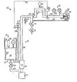
- An advantageous exemplary embodiment is shown in FIG. 1 and described in more detail below.
- the figure shows a schematic representation of the construction of the breathing apparatus according to the invention.
- the breathing apparatus 10 for connection to a patient 11 consists of an inspiratory branch 12 and an expiratory branch 13. Between these two branches, a patient connection tee 14 is provided, i. a. via a connection by means of a patient hose system 44.
- the desired gas mixture - normally room air enriched with oxygen - is supplied from a high-pressure gas mixer 15 into the inspiration channel 16 of the inspiration branch 12.
- the gas supplied by the high-pressure gas mixer at approx. 5 bar is reduced to a lower pressure via a rotameter 17 with a throttle valve.
- a pressure is set by a so-called peep valve 18 in the inspiration branch 12, which is approximately 5-10 mbar above normal pressure.
- a one-way valve 19 is also provided in the inspiration branch 12 in the area of the inspiration outlet.
- the inspiration branch 12 consists of a direct supply part with the inspiration channel 16 and a memory 20.
- the memory 20 consists of a pressure stabilizer 21 d. H.
- a bellows 23 under spring pressure This bellows 23 is filled by the high-pressure gas mixer 15 via the line 24 and a level control valve 25.
- two drive variants for the bellows 23 are shown, with the aid of which the bellows can be pressed together and the pressure stabilizer can be emptied.
- a hydraulic or pneumatic drive unit consisting of a working cylinder 26 with a drive piston, is provided for this purpose.
- the drive can also have an electric drive 27, for. B. a stepper motor or linear motor.
- the springs 22 serve to reset the bellows 23.
- the pressure in the bellows corresponds approximately to the peep level, but is expediently set about 5 mbar higher.
- the bellows are emptied via a line 28 and a controllable valve 29.
- the expiratory branch 13 consists of an expiratory channel 30 at the end of which an expiration valve 31 connects, which can be designed as a peep valve known per se.
- the expiration valve 31 only has the function open / closed. In order to maintain the continuously positive airway pressure (CPAP), however, it must close to a certain pressure level (peep level). This can be achieved in a simple manner in that the inspiratory channel 16 is connected to a pneumatic device 33 of the expiration valve 31 via a pressure line 32.
- the pressure in line 16 acts on a piston 34, the piston rod of which rests on a sealing plate 35 acts, which seals the outlet of the expiratory channel 30 similar to a valve seal.
- the expiration valve 31 also has a breathing gas outlet 36.
- the expiration channel 30 has a number of measuring devices. These are in particular a pressure sensor 37 with a measuring amplifier 38 which is connected via a line 39 to the solenoid valve 29 of the pressure stabilizer device 21. Furthermore, a pressure display 40 and a. Flow meter 41 each provided with an alarm indicator.
- a controllable on / off valve 42 additionally connected downstream of the peep valve 18 enables the above-described expansion of the device as a respirator (flow chopper).
- a safety valve 43 in the inspiration branch prevents an event. overpressure in the event of incorrect control of valve 42 or other units.
- peep valve 18 Due to the arrangement of the peep valve 18 in the inspiration branch 12, only the gas which is directly required reaches the patient 11. The rest flows out via the peep valve (overflow valve) 18, whereby the set pressure level (peep level) is simultaneously reached and the solenoid valve 29 is closed again.
- the patient 11 During the subsequent expiration, the patient 11 generates an overpressure in the system which is dependent on the flow resistance and the expiration gas velocity, as a result of which the one-way valve 19 is closed and the expiration valve 31 is opened.
- the expired air then reaches the expiration valve 31 via the measuring devices 40, 41 and from there via the outlet 36 to the surroundings.
- Due to the pneumatic device 33 - 35 arranged in the expiration valve 31, the pressure prevailing in the expiration channel 30 must be greater than the set peep level so that the expiration air can leave the outlet 36 of the expiration valve 31.
- the patient is therefore constantly under the positive airway pressure (CPAP) set by the peep level.
- CPAP positive airway pressure
- the system of the pressure stabilizer 21 is refilled and the gas flow set on the rotameter 17 is discharged via the peep valve.
- the overpressure generated by the patient in the system slowly drops until the pressure set on the valve 18 level the expiration valve 31 closes again.
- the fluctuation range of the airway pressure around the peep level which is approx. 5 - 10 mbar, d. H. the undershoot and overshoot ranges around the set pressure level amount to a maximum of 3 mbar with the device according to the invention.
- This effect results from the soft coupling of the device to the patient and a set low flow, i. H. a constant minimum amount of gas, as well as a fast response time and gas supply to the pressure control device 21.
- the peep valve is no longer located at the end of the expiration branch, but in the inspiration branch, so that the expiration branch only absorbs exhaled air from the patient got to. This enables lower respiratory pressure ratios or pressure fluctuations and precise measurement of the respiratory volume.
- the invention is not restricted to the exemplary embodiment shown and described. It also includes all professional modifications and further training as well as partial and / or sub-combination of the features and measures described and / or shown.
Landscapes
- Health & Medical Sciences (AREA)
- Pulmonology (AREA)
- Emergency Medicine (AREA)
- Engineering & Computer Science (AREA)
- Anesthesiology (AREA)
- Biomedical Technology (AREA)
- Heart & Thoracic Surgery (AREA)
- Hematology (AREA)
- Life Sciences & Earth Sciences (AREA)
- Animal Behavior & Ethology (AREA)
- General Health & Medical Sciences (AREA)
- Public Health (AREA)
- Veterinary Medicine (AREA)
- Measurement Of The Respiration, Hearing Ability, Form, And Blood Characteristics Of Living Organisms (AREA)
- Respiratory Apparatuses And Protective Means (AREA)
Abstract
Description
- Die Erfindung betrifft ein Atemhilfegerät (Respirator) zur Wiederherstellung der Spontanatmung von Patienten, mit einem inspiratorischem und einem expiratorischem Zweig, wobei ein kontinuierlich positiver Atemwegdruck (CPAP) mittels eines Überströmventils oder dergleichen (Peep-Ventil) auf Peep-Niveau einstellbar ist.
- Die in den letzten Jahren wesentlich erweiterte Indikationsstellung in Bezug auf die Schwere der operativen Eingriffe und das Patientenalter, erfordert eine dementsprechende Entwicklung der Beatmungstechnik. Aus der anfänglichen, einfachen Unterstützung der Spontanatmung während längerer Narkosen entwickelte sich eine sogenannte Atemtherapie, die sich zahlreicher Beatmungsformen und -geräten bedient.
- Der schwierigste Abschnitt jeder Respirator-Therapie umfasst die Entwöhnung und Wiederherstellung der Spontanatmung des Patienten nach länger dauernder Beatmung auf der Intensivstation. Als letzter Schritt der Ubergangsphase findet heute die sogenannte CPAP-Atmung Anwendung. Hierbei atmet der Patient spontan an einem Beatmungsgerät mit einem um 5 - 10 mbar erhöhtem
- Gesamtdruckniveau. Durch diese Maßnahme wird die Lunge dauernd in einem geblähten und damit volumenvergrößerten Zustand gehalten, so daß eine verbesserte Sauerstoffzuführung erzielt und die ggf. hochfrequente Hechelatmung unterdrückt werben kann.
- Zur Durchführung der CPAP-Atmung, d. h. einer Atmung unter einem kontinuierlich positiven Atemwegdruck, werden entweder schwere Beatmungsmaschinen, die über diese Beatmungsform verfügen oder aber spezielle CPAP-Geräte eingesetzt. Die Erzeugung und Sicherstellung des andauernden positiven Druckniveaus im gesamten Respirationstrakt erfolgt bei den bekannten Geräten nach zwei Prinzipien, nämlich dem High-Flow-CPAP oder dem Demand-CPAP.
- Beim High-Flow-CPAP wird dem Patienten ein ständiger Gasstrom angeboten. Der gewünschte Überdruck im Respirationstrakt wird durch ein Überdruckventil bestimmt, z. B. durch die Eintauchtiefe eines Expirationsrohres in einem Wasserschloß. High-Flow-CPAP-Geräte sind zwar preisgünstig, sie weisen jedoch eine Reihe konstruktiv bedingter Nachteile auf. Hier sind insbesondere die großen expiratorischen Atemwegwiderstände, d. h. Widerstände beim Ausatmen des Patienten zu nennen, mit den entsprechenden negativen Uber- und Unterschwingweiten un das gewünschte am Gerät eingestellte Druckniveau (Peep-Niveau) .
- Durch das High-Flow-CPAP-Gerät fließt demnach ein standiger Gasstrom unter einem positiven Druckniveau von 5 - 1C mbar.
- Dem Patienten steht deshalb ein ständiger Gasstrom über
ein Patienten-Anschluß-T-Stück zur Verfügung. Da der Gasverbrauch auf die höchstmögliche Entnahme des Patienten eingestellt werden muß, ergibt sich ein hoher Gasverbrauch dadurch, daß in der Expirationsphase das Gas ungenutzt aus dem Überstrcimventil (Peep-Ventil) ausströmt. Die hohen Atemwegwiderstände in der Expirationsphase ergeben sich dadurch, daß zusätzlich zum ständigen Gasfluß die ausgeatmete Luft hinzukommt, so daß sich eine Druckerhöhung im expiratorischem Atemzweig einstellt. infolge des beim Einatmen auftretenden Unterdrucks im inspiratorischen- infolge des Gasstaus auftretende Überdrucks im expiratorischen Zweig stellen sich bei den bekannten High-Elow-CPAP-Gerät große Unter- und Uberschwingweiten der Atemdruckkurve um das eingestellte Peep-Niveau ein. Dies stellt jedoch eine zusätzliche Belastung des Patienten dar. - Da der expiratorische Zweig in der Ausatmungsphase sowohl den ständigen Gasstrom als auch die ausgeatmete Luft aufnimmt, ist eine Messung des Atemvolumens nicht oder nur unzureichend über eine Differenzmessung möglich, wobei Gasverluste im System zu berücksichtigen wären. Die Messung des Atemvolumens ist jedoch für die Feststellung des Sauerstoffgehalts im Blut von großer Bedeutung.
- Beim Demand-CPAP, welches hauptsächlich in schweren Beatmungsgeräten zu finden ist, wird der vom Patienten gewünschte inspiratorische Gasstrom über einen Drucksensor und ein
regelbares Inspirationsventil bedarfsgerecht angeboten. Hierdurch werden die Nachteile des High-Flow-CPAP zwar teilweise vermieden, da nur das jeweils gewünschte Atemzugvolumen geliefert und die vorhandenen Monitoringsysteme benützt werden können. Nachteilig wirken sich jedoch die erforderlichen Mess-und Schaltzeiten des Drucksensors und des Inspirationsventils aus, d. h., der Patient bekommt das Atemgas zunächst nicht oder in zu geringer Menge und später schubweise oder in zu großen Mengen geliefert. - Die zusätzlich erforderlichen Expirationsventile weisen ferner erhebliche Strömungswiderstände auf oder begrenzen infolge un- genügender öffnungswinkel die Strömungsgeschwindigkeit der Expirationsluft. Während der Expirationsphase wird der Atemwegdruck von einem Druckwandler in der Expirationsseite gemessen. Das Signal vom Wandler wird mit dem vorgegebenen Peep-Niveau verglichen. Eine Differenz zwischen tatsächlichem und eingestellten Wert resultiert in einem Signal an das Expirationsventil. Dieses Signal korrigiert das Expirationsventil ständig, so daß das gewünschte Peep-Niveau erhalten wird.
- Da das Expirationsventil während der Inspirations- und Pausenphase geschlossen bleibt und danach geregelt öffnet, ergeben sich auch hier Zeitverzögerungen und damit verbundene Druckschwankungen, die sich auf die gewünschte Uberschwingweite des Druckniveaus ebenfalls negativ auswirken.
- Es ist deshalb grundsätzlich festzustellen, daß weder das High-Flow- noch das Demand-System den Erfordernissen einer idealen CPAP-Atmung d. h. einer Atmung mit möglichst kleinen Unter- und Überschwingweiten um das eingestellte Druckniveau gerecht wird.
- Da das Demand-CPAP-System nur in schweren und damit teueren Beatmungsmaschinen zu finden ist, werden die Patienten normalerweise mit dem High-Flow-CPAP-System behandelt. Die auch hiermit verbundenen Nachteile wurden bereits angegeben.
- Der Erfindung liegt die Aufgabe zugrunde, ein kostengünstiges Atemhilfegerät der eingangs erläuterten Art zu schaffen, welches in der Expirationsphase einen möglichst geringen Atemwegwiderstand aufweist, welches eine verzögerungsfreie und damit "weiche* Kopplung zwischen Patient und Gerät in der Inspirationsphase ermöglicht, und bei welchem der Atemluftdruck beim Inspirieren und Expirieren nur geringfügig und in definierter Größe um das benötigte Druckniveau unter- bzw. überschwingt, d. h. eine möglichst geringe Patientenbelastung hervorruft. Eine weitere wesentliche Aufgabe liegt in der Schaffung einer Meßbarkeit des Atemvolumens. Eine weitere Aufgabe liegt darin, das erfindungsgemäße Atemhilfegerät derart auszubilden, daß ein geringerer ständiger Gasstrom als bei bekannten Geräten ständig anaeboten wird und Bedarfspitzen zusätzlich in das System eingespeist werden (Low-Flow-CPAP-System) . Aufgabe der Erfindung ist es weiterhin, die Verwendungsgemöglichkeit des Geräts zu erhöhen.
- Diese Aufgabe wird durch die Merkmale des Anspruchs 1 und insbesondere dadurch gelöst, daß im inspiratorischen Zweig des Atemhilfegeräts ein dauernd fließendes Gasgemisch vorgesehen ist, dessen Druck durch das hieran angeschlossene Peep-Ventil bestimmbar ist, und daß der expiratorische Zweig des Atemhilfegeräts durch ein vom Peep-Niveau abhängiges Expirationsventil und/oder Peep-Ventil verschließbar ist.
- Die Erfindung vereint demnach die Vorteile beider bekannten Systeme, ohne die Hauptnachteile in Kauf nehmen zu müssen. Die konstruktive Ausführungsform des erfindungsgemäßen Gerätes stellt ebenfalls eine Kombination der bekannten Systeme jedoch mit dem wesentlichen Unterschied dar, daß das Ventil zur Einstellung des Druckniveaus (Peep-Ventil) nicht mehr im Expirationszweig wie beim High-Flow-CPAP-System, sondern im Inspirationszweig angeordnet ist, und daß das erfindungsgemäße Expirationsventil nur noch eine Auf/Zu Funktion hat.
- Ähnlich wie beim High-Flow-CPAP-System erfolgt demnach eine weiche Kopplung" zwischen Atemhilfegerät und Patient durch einen ständigen Gasstrom. Schaltverzögerungen, die beim Triggern der schweren Beatmungsmaschine mit Hilfe des beim Atmungsvorgang entstehenden Unterdrucks entstehen, treten nicht auf, so daß die Unterschwingweiten des Druckniveaus klein gehalten werden können. Da sich das Peep-Ventil erfindungsgemäß im Inspirationszweig des Atemhilfegeräts befindet, strömt im Expirationszweig nur noch die ausgeatmete Luft des Patienten, wodurch der Atemwegwiderstand erheblich reduziert wird und eine genaue Messung des Atemvolumens möglich wird, zur Feststellung der Spontanatemfähigkeit, der Beatmungsparameter, wie Atemfrequenz, CO2- und O2-Austausch (Monotoring). Außerdem wird nunmehr eine automatische Überwachung ermöglicht. Die Messung im Expirationszweig ist auch insofern wichtig, da derartige Geräte eine gewiße Leckrate aufweisen, d. h. bei Messung des Durchgangsvolumens im Inspirationszweig ist nicht erkennbar, inwieweit hier noch Leckverluste auftreten werden. Das am Ende des Inspirationszweigs angeordnete Expirationsventil hat lediglich eine Auf/Zu Funktion, d. h. über dem eingestellten Druckniveau (Peep-Niveau) kann die ausgeatmete Luft das Ventil passieren. Es kann deshalb auch als bekanntes Peep-Ventil ausgebildet sein.
- Durch die in den Unteransprüchen aufgeführten Maßnahmen ist eine vorteilhafte Weiterbildung und Verbesserung des im Hauptanspruch angegebenen Atemhilfegerätsmöglich.
- Gemäß der vorteilhaften Ausbildung nach Unteranspruch 2 wird der inspiratorische Zweig des Atemhilfegerät während der Expirationsphase vom expiratorischen Zweig durch ein Einwegventil oder Rückschlagventil, insbesondere durch ein an sich bekanntes Glimmerventil abgetrennt. Dieses Ventil ist derart eingestellt, daß es sich'beim Aufbau eines über dem Peep-Niveau liegenden Druckes im expiratorischen Zweig schließt, hervorgerufen durch den Ausatmungsvorgang des Patienten. Das Einwegventil wird möglichst nahe zum Patienten-anschluß gelegt, um möglichst den gesamten inspiratorischen Zweig während der Expirationsphase abzuschließen, bzw. den Druckverlust und damit den Atemwegwiderstand im inspiratorischen Zweig so gering als möglich zu halten.
- Gemäß dem Unteranspruch 3 hat sich als einfaches Peep-Ventil ein Standrohr mit Wasserschloß bewährt, dessen Druckniveau von 5 - 10 mbar einstellbar ist. In bestimmten Anwendungsfällen sind jedoch auch niedrigere oder höhere Drücke notwendig.
- Gemäß den weiteren Unteransprüchen ist eine vorteilhafte Ausbildung des Expirationsventils vorgesehen, wobei gewährleistet sein muß, daß beim Ausatmen (Expirationsphase) das Mindestdruckniveau erhalten bleiben muß, d. h. das Ausatmen gegen den Druck des Peep-Niveaus erfolgt. Dies kann entweder auf einfache Weise ein Peep-Ventil selbst, oder ein durch ein vom inspiratorischen Zweig gesteuertes Druckventil sein. Eine aufwendigere und wieder mit Zeitverzögerung arbeitende Methode stellt ein regelbares Expirationsventil dar.
- Um den Nachteil des hohen Gasverbrauches bei den bekannten High-Flow-CPAP-Geräten zu vermeiden, arbeitet die Erfindung in einem bevorzugten Ausführungsbeispiel nach einem Low-Flow-CPAP-Prinzip, d. h. als ständiger Gasfluß wird eine niedrigere Gasmenge gewählt. Sofern der Patient einen höheren inspiratorischen Gasbedarf hat, sieht die Erfindung einen zusätzlichen Druckkonstanthalter vor, dessen Gas bei Bedarf dem inspiratorischen Zweig zugegeben wird. Um den Druckkonstanthalter zu füllen, ist ein Hochdruckgasmischer vorgesehen, der den Faltenbalg des Druckkonstanthalters bereits während der Entleerung und der expiratorischen Phase mit Gas wieder füllt. Eine Drosseleinrichtung senkt den Druck des Hochdruckgasmischers auf den Druck im inspiratorischen Zweig, d. h. auf Peep-Niveau. Diese Drosseleinrichtung kann als Durchflußmesser mit Einstellventil zur Druckreduzierung ausgebildet sein. Der Druck im Druckkonstanthalter kann geringfügig über dem Druck des Peep-Niüeaus liegen.
- Durch vorstehende Maßnahme ist eine erhebliche Gasverbrauchsreduzierung und damit Kostenreduzierung möglich, wobei auf den Vorteil der "weichen Kopplung" zwischen Gerät und Patient nicht verzichtet werden braucht.
- Durch die erfindungsgemäßen Maßnahmen werden demnach die,Vorteile der bekannten Geräte vereinigt, ohne daß deren Nachteile - außer einem geringen Gasverbrauch - in Kauf zu nehmen sind. Das erfindungsgemäße Gerät ist derart einfach konstruiert, daß es preismäßig mit dem High-Flow-CPAP-Gerät konkurieren kann, jedoch nicht dessen Nachteile, insbesondere im expiratorischen Zweig aufweist. Das Gerät liefert unter dem jeweils eingestellten Atemwegdruck das vom Patienten benötigte Volumen. Hat der Patient seinen Bedarf gedeckt, so wird keine aufwendige Regelung benötigt, da das Einwegventil den inspiratorischen Zweig abtrennt und die Expiration,erfolgen kann. Während dessen entweicht das laufend gelieferte Gas über das Peep-Ventil, ohne daß eine Regelung oder Steuerung eines Inspirationsventils notwendig ist. Der Patient hat immer die Möglichkeit, das Atmungsvolumen beliebig durch Eigenatmung zu vergrößern. Dabei ist der Patient durch geringe Unter- und Überschwingweiten um das eingestellte Peep-Niveau minimalst belastet. In Abwandlung eignet sich die Erfindung jedoch auch ohne die Einstellung eines ständigen positiven Atemwegdrucks (CPAP), bzw. einem Atemwegdruck der nahezu als Normaldruck zu bezeichnen wäre. Dies kann entweder durch Einstellung am Peep-Ventil selbst oder ohne irgend ein spezielles Ventil geschehen.
- In Ausgestaltung der Erfindung kann diese auch auf vorteilhafte Weise als Beatmungsgerät ("Flow-Zerhacker") verwendet werden, indem ein über eine Zeit-Takt-Schaltung geregeltes Auf-/Zu-Ventil dem Peep-Ventil nachgeschaltet wird. Durch Schließen bzw. Regelung des Ventils kann eine zusätzliche Beatmung in den verschiedensten Formen erfolgen.
- Ein zusätzliches Überdruck-Sicherheitsventil dient der Sichorheit des Patienten bei Gerät- bzw. Ventilstörungen. Ein vorteilhaftes Ausführungsbeispiel ist in der Fig. dargestellt.und nachfolgend näher beschrieben.
- Die Figur zeigt eine schematische Darstellung des Aufbaus des erfindungsgemäßen Atemhilfegeräts.
- Das erfindungsgemäße Atemhilfegerät 10 zum Anschluß an einen Patienten 11 besteht aus einem inspiratorischen Zweig 12 und einen expiratorischem Zweig 13. Zwischen diesen beiden Zweigen ist ein Patienten-Anschluß-T-Stück 14 vorgesehen, i. a. über einen Anschluß mittels eines Patienten-Schlauchsystems 44.
- Von einem Hochdruckgasmischer 15 wird das jeweils gewünschte Gasgemisch - normalerweise mit Sauerstoff angereicherte Raumluft - in den Inspirationskanal 16 des Inspirationszweigs 12 geliefert. Das vom Hochdruckgasmischer mit ca. 5 bar gelieferte Gas wird über ein Rotameter 17 mit Drosselventil auf einen niedrigeren Druck abgesenkt. Durch ein sogenanntes Peep-Ventil 18 im Inspirationszweig 12 wird ein Druck eingestellt, der etwa 5 - 10 mbar über dem Normaldruck liegt.
- Im Inspirationszweig 12 ist weiterhin im Bereich des Inspirationsausganges ein Einwegventil 19 vorgesehen.
- Der Inspirationszweig 12 besteht aus einem Direktversorgungsteil mit dem Inspirationskanal 16 und einem Speicher 20. Der Speicher 20 besteht aus einem Druckkonstanthalter 21 d. h.
- einem unter dem Federdruck stehender Faltenbalg 23. Dieser Balg 23 wird über die Leitung 24 und einem Füllstandsregelventil 25 von dem Hochdruckgasmischer 15 gefüllt. In dem dargestellten Ausführungsbeispiel.sind zwei Antriebsvarianten für den Balg 23 dargestellt, mit deren Hilfe der Balg zusammengepreßt und der Druckkonstanthalter entleert werden kann. Zum einen ist-hierzu eine hydraulische oder pneumatische Antriebseinheit, bestehend aus einem Arbeitszylinder 26 mit Antriebskolben vorgesehen. Der Antrieb kann aber auch über einen elektrischen Antrieb 27, z. B. einem Schrittmotor oder Linearmotor erfolgen. Die Federn 22 dienen der Rückstellung des Balg 23. Der Druck-im Balg entspricht etwa dem Peep-Niveau, wird jedoch zweckmäßigerweise ca. 5 mbar höher eingestellt.
- Die Entleerung des Balgs erfolgt über eine Leitung 28 und einem regelbaren Ventil 29.
- Der expiratorische Zweig 13 besteht aus einem expiratorischen Kanal 30 an dessen Ende sich ein Expirationsventil 31 anschließt, welches als ansich bekanntes Peep-Ventil ausgebildet sein kann.
- Das Expirationsventil 31 hat lediglich die Funktion auf/zu. Um den kontinuierlich positiven Atemwegdruck (CPAP) zu erhalten muß es jedoch bis zu einem bestimmten Druckniveau (Peep-Niveau) schließen. Dies läßt sich auf einfache Weise dadurch erreichen, daß der inspiratorische Kanal 16 über eine Druckleitung 32 mit einer Pneumatikeinrichtung 33 des Expirationsventils 31 verbunden ist. Der Druck in der Leitung 16 (Peep-Niveau) beaufschlagt einen Kolben 34, dessen Kolbenstange auf einen Dichtungsteller 35 einwirkt, der ähnlich einer Ventilabdichtung, den Ausgang des expiratorischen Kanals 30 abdichtet. Das Expirationsventil 31 weist weiterhin einen Atemgasaustritt 36 auf. Der Expirationskanal 30 weist eine Reihe von Messeinrichtungen auf. Dies sind insbesondere ein Drucksensor 37 mit Messverstärker 38 der über eine Leitung 39 mit dem Magnetventil 29 der Druckkonstanthaltereinrichtung 21 verbunden ist. Weiterhin sind eine Druckanzeige 40 sowie ein. Strömungsmesser 41 jeweils mit Alarmanzeige vorgesehen.
- Ein dem Peep-Ventil 18 zusätzlich nachgeschaltetes regelbares Auf-/Zu-Ventil 42 ermöglicht die schon beschriebene Erweiterung des Gerätes als Beatmungsgerät (Flow-Zerhacker). Ein Sicherheitsventil 43 im Inspirationszweig verhindert einen event. überdruck bei fehlerhafter Regelung des Ventils 42 bzw. sonstigen Aggregaten.'
- Die prinzipielle Funktionsweise eines CPAP-Atemhilfegerätswurde schon eingangs ausführlichst geschildert. Nachstehend seien noch die Unterschiede des Ausführungsbeispiels zum Stand der Technik erläutert:
- Während der Inspiration des Patienten 11 gelangt der am Rotameter 17 eingestellte Gasstrom unmittelbar über die Leitung 16 ; zum Patienten, da im Inspirationszweig 12 ein Sog entsteht und das,Expirationsventil 31 geschlossen ist. Reicht der eingestellte Gasstrom nicht aus, dann sinkt der Gesamtdruck im System solange ab, bis der durch den Drucksensor 37 festgestellte Druck eine eingestellte Unterdruckgrenze erreicht und dadurch vom Messverstärker 31 ein Signal an das Magnetventil 29 geleitet wird. Durch öffnen des Ventils 29 gelangt ein zusätzliches Gasvolumen aus dem Druckkonstanthalter 21 in den Inspirations- kanal 16 und damit zum Patienten.
- Durch die Anordnung des Peep-Ventils 18 im Inspirationszweig 12, gelangt nur das unmittelbar benötigte Gas zum Patienten 11. Der Rest strömt über das Peep-Ventil (Überströmventil) 18 ins Freie ab, wodurch gleichzeitig das eingestellte Druckniveau (Peep-Niveau) erreicht und das Magnetventil 29 wieder geschlossen wird.
- Bei der darauffolgenden Expiration erzeugt der Patient 11 einen vom Strömungswiderstand und der Expirations-Gasgeschwindigkeit abhängigen Überdruck im System, wodurch das Einwegventil 19 geschlossen und das Expirationsventil 31 geöffnet wird. Die expirierte Luft gelangt dann über die Messeinrichtungen 40, 41 zum Expirationsventil 31 und von dort über den Ausgang 36 in die Umgebung. Durch die im Expirationsventil 31 angeordnete Pneumatikeinrichtung 33 - 35, muß der im Expirationskanal 30 herrschende Druck größer sein als das eingestellte Peep-Niveau, damit die Expirationsluft den Ausgang 36 des Expirationsventils 31 verlassen kann. Der Patient steht deshalb ständig unter dem durch das Peep-Niveau eingestellten positiven Atemwegdruck (CPAP).
- Während der Expirationsphase wird das System des Druckkonstanthalters 21 wieder aufgefüllt und der am Rotameter 17 eingestellte Gasstrom über das Peep-Ventil abgeleitet. Am Ende der Expiration sinkt der vom Patienten im System erzeugte Überdruck langsam ab, bis das am Ventil 18 eingestellte Druckniveau das Expirationsventil 31 wieder schließt.
- Die Schwankungsbreite des Atemwegdrucks um das Peep-Niveau, welches ca. 5 - 10 mbar beträgt, d. h. die Unter- und Uberschwingweiten um das eingestellte Druckniveau betragen mit der erfindungsgemäßen Einrichtung maximal 3 mbar. Diese Wirkung ergibt sich durch das weiche Ankoppeln des Geräts an den Patienten und einem eingestellten Low-Flow, d. h. einer konstanten minimalen Gasmenge, sowie einer schnellen Ansprechzeit und Gaszuführung der Druckkonstanthalteeinrichtung 21. Dabei ist es von besonderer Bedeutung, daß das Peep-Ventil nicht mehr am Ende des Expirationszweigs, sondern im Inspirationszweig angeordnet ist, so daß der Expirationszweig ausschließlich ausgeatmete Luft vom Patienten aufnehmen muß. Dies ermöglicht niedrigere Atemweq-Druckverhältnisse bzw. Druck--.schwankungen und qenaue Messung des Atemvolumens.
- Die Erfindung ist nicht auf das dargestellte und beschriebene Ausführungsbeispiel beschränkt. Sie umfaßt auch alle fachmännischen Abwandlungen und Weiterbildungen sowie Teil- und/ oder Unterkombination der beschriebenen und/oder dargestellten Merkmale und Maßnahmen.
Claims (13)
Applications Claiming Priority (2)
| Application Number | Priority Date | Filing Date | Title |
|---|---|---|---|
| DE19823240897 DE3240897A1 (de) | 1982-11-05 | 1982-11-05 | Atemhilfegeraet |
| DE3240897 | 1982-11-05 |
Publications (3)
| Publication Number | Publication Date |
|---|---|
| EP0112979A2 true EP0112979A2 (de) | 1984-07-11 |
| EP0112979A3 EP0112979A3 (en) | 1984-09-26 |
| EP0112979B1 EP0112979B1 (de) | 1987-02-04 |
Family
ID=6177383
Family Applications (1)
| Application Number | Title | Priority Date | Filing Date |
|---|---|---|---|
| EP83109830A Expired EP0112979B1 (de) | 1982-11-05 | 1983-10-01 | Atemhilfegerät |
Country Status (2)
| Country | Link |
|---|---|
| EP (1) | EP0112979B1 (de) |
| DE (2) | DE3240897A1 (de) |
Cited By (6)
| Publication number | Priority date | Publication date | Assignee | Title |
|---|---|---|---|---|
| WO1991012033A1 (en) * | 1990-02-07 | 1991-08-22 | Flow-Meter S.P.A. | Jar for picking up and retaining liquids |
| US5520172A (en) * | 1992-04-16 | 1996-05-28 | Obermayer; Anton | Anesthetic machine |
| EP0917883A1 (de) * | 1997-11-20 | 1999-05-26 | Siemens-Elema AB | Gasdruckerzeuger für ein Beatmungsgerät |
| EP1230942A3 (de) * | 2001-02-07 | 2004-01-21 | Siemens-Elema AB | Gasbehälter |
| EP1898979A4 (de) * | 2005-07-04 | 2011-06-01 | Lifevent Medical Ltd | Kontinuierliches positiv-atemwegsdruckgerät |
| US10589042B2 (en) | 2011-11-11 | 2020-03-17 | ResMed Pty Ltd | Exchanger assembly for respiratory treatment |
Families Citing this family (6)
| Publication number | Priority date | Publication date | Assignee | Title |
|---|---|---|---|---|
| DE3712388A1 (de) * | 1987-04-11 | 1988-10-27 | Obermayer Anton | Atemhilfegeraet |
| DE3712389C2 (de) * | 1987-04-11 | 2000-01-05 | Anton Obermayer | Atemhilfegerät |
| DE3820043C2 (de) * | 1987-11-20 | 1999-10-28 | Anton Obermayer | Atemhilfegerät |
| EP0346527B1 (de) * | 1988-06-13 | 1993-03-03 | Anton Dr.-Ing. Obermayer | Atemhilfegerät |
| DE102007014465A1 (de) * | 2006-04-01 | 2007-12-06 | Weinmann Geräte für Medizin GmbH & Co. KG | Peep-Ansteuerung |
| DE102015105677B4 (de) * | 2015-04-14 | 2021-12-09 | Hunger Maschinen Gmbh | Hydraulische Schmiedepresse mit einem Regulierventil zur Füllstandsregulierung |
Family Cites Families (6)
| Publication number | Priority date | Publication date | Assignee | Title |
|---|---|---|---|---|
| US2584450A (en) * | 1947-09-02 | 1952-02-05 | Univ Minnesota | Tracheotomy inhaler apparatus |
| US4082093A (en) * | 1977-04-27 | 1978-04-04 | Bourns, Inc. | Compensator valve |
| GB1583273A (en) * | 1977-05-06 | 1981-01-21 | Medishield Corp Ltd | Lung ventilators |
| DE2801546C2 (de) * | 1978-01-14 | 1982-09-09 | Drägerwerk AG, 2400 Lübeck | Beatmungsgerät insbesondere für Kleinkinder |
| SE418456B (sv) * | 1979-06-21 | 1981-06-09 | Engstrom Medical Ab | Respiratoranordning |
| US4459983A (en) * | 1979-07-24 | 1984-07-17 | Christian Beyreuther | Breathing apparatus for reanimation of newborns |
-
1982
- 1982-11-05 DE DE19823240897 patent/DE3240897A1/de not_active Withdrawn
-
1983
- 1983-10-01 EP EP83109830A patent/EP0112979B1/de not_active Expired
- 1983-10-01 DE DE8383109830T patent/DE3369648D1/de not_active Expired
Cited By (10)
| Publication number | Priority date | Publication date | Assignee | Title |
|---|---|---|---|---|
| WO1991012033A1 (en) * | 1990-02-07 | 1991-08-22 | Flow-Meter S.P.A. | Jar for picking up and retaining liquids |
| US5520172A (en) * | 1992-04-16 | 1996-05-28 | Obermayer; Anton | Anesthetic machine |
| EP0917883A1 (de) * | 1997-11-20 | 1999-05-26 | Siemens-Elema AB | Gasdruckerzeuger für ein Beatmungsgerät |
| US6234170B1 (en) | 1997-11-20 | 2001-05-22 | Siemens Elema Ab | Gas pressure generator |
| EP1230942A3 (de) * | 2001-02-07 | 2004-01-21 | Siemens-Elema AB | Gasbehälter |
| EP1898979A4 (de) * | 2005-07-04 | 2011-06-01 | Lifevent Medical Ltd | Kontinuierliches positiv-atemwegsdruckgerät |
| US8136522B2 (en) | 2005-07-04 | 2012-03-20 | Lifevent Medical Limited | Continuous positive airway pressure device |
| CN101217993B (zh) * | 2005-07-04 | 2013-06-12 | 莱夫文特医疗有限公司 | 连续气道正压通气装置 |
| US10589042B2 (en) | 2011-11-11 | 2020-03-17 | ResMed Pty Ltd | Exchanger assembly for respiratory treatment |
| US11957835B2 (en) | 2011-11-11 | 2024-04-16 | ResMed Pty Ltd | Exchanger assembly for respiratory treatment |
Also Published As
| Publication number | Publication date |
|---|---|
| DE3240897A1 (de) | 1984-05-10 |
| EP0112979A3 (en) | 1984-09-26 |
| DE3369648D1 (en) | 1987-03-12 |
| EP0112979B1 (de) | 1987-02-04 |
Similar Documents
| Publication | Publication Date | Title |
|---|---|---|
| DE69318982T2 (de) | Atemhilfsgerät | |
| DE19516536C2 (de) | Beatmungsgerät | |
| DE4432219C1 (de) | Beatmungssystem zur Versorgung eines Patienten mit Atemgas | |
| DE69822886T2 (de) | Kolben-beatmungsgerät mit sauerstoff mischung | |
| EP0491969B1 (de) | Beatmungsgerät mit vom Patientengasfluss abhängiger Triggerempfindlichkeit | |
| EP1377347B1 (de) | Trainingsgerät für die Atmungsfunktion und Verfahren zur Überwachung der Frischluftzufuhr | |
| DE3586895T2 (de) | Beatmungssystem. | |
| DE3537507C2 (de) | Gerät zur unterstützenden intermittierenden Druckbeatmung und Aerosol-Therapie | |
| DE69621397T2 (de) | Narkosesystem | |
| DE69121781T2 (de) | Gerät und Verfahren zur Strömungsauslösung bei atmungsunterstützter Beatmung | |
| DE69314513T2 (de) | Durchflussregelung eines unter Druck stehenden Gases | |
| EP0033732A1 (de) | Beatmungsgerät zur reanimation von neugeborenen. | |
| WO2007068132A1 (de) | Schlauchsystem für beatmungsgeräte | |
| DE2723768A1 (de) | Beatmungsgeraet | |
| DE4312510A1 (de) | Anästhesiemaschine | |
| DE2552148A1 (de) | Kleinkind- und jugend-volumen-atemgeraet | |
| DE102009003605A1 (de) | System und Verfahren zur integrierten hochfrequenten oszillatorischen Beatmung | |
| EP0112979B1 (de) | Atemhilfegerät | |
| DE2910094A1 (de) | Automatisches beatmungsgeraet mit leistungskontrolle, insbesondere fuer wiederbelebungs- und anaesthesie-zwecke | |
| DE2806750A1 (de) | Handbeatmungsvorrichtung fuer beatmungsgeraete | |
| DE69418514T2 (de) | Vorrichtung und Verfahren zur Steuerung eines geschlossenen Regelkreises zum Einatmungsdruck in einem Beatmungsgerät | |
| DE3712388C2 (de) | ||
| DE3435900A1 (de) | Einrichtung zum intermittierenden aufblasen eines cuffs fuer ein patienten-beatmungsgeraet | |
| DE2601902A1 (de) | Beatmungsgeraet, speziell zur anwendung bei der anaesthesie und zur langdauernden wiederbelebung | |
| DE1227199B (de) | Beatmungsgeraet |
Legal Events
| Date | Code | Title | Description |
|---|---|---|---|
| PUAI | Public reference made under article 153(3) epc to a published international application that has entered the european phase |
Free format text: ORIGINAL CODE: 0009012 |
|
| AK | Designated contracting states |
Designated state(s): CH DE FR GB LI SE |
|
| PUAL | Search report despatched |
Free format text: ORIGINAL CODE: 0009013 |
|
| AK | Designated contracting states |
Designated state(s): CH DE FR GB LI SE |
|
| 17P | Request for examination filed |
Effective date: 19850316 |
|
| GRAA | (expected) grant |
Free format text: ORIGINAL CODE: 0009210 |
|
| AK | Designated contracting states |
Kind code of ref document: B1 Designated state(s): CH DE FR GB LI SE |
|
| REF | Corresponds to: |
Ref document number: 3369648 Country of ref document: DE Date of ref document: 19870312 |
|
| ET | Fr: translation filed | ||
| PLBE | No opposition filed within time limit |
Free format text: ORIGINAL CODE: 0009261 |
|
| STAA | Information on the status of an ep patent application or granted ep patent |
Free format text: STATUS: NO OPPOSITION FILED WITHIN TIME LIMIT |
|
| 26N | No opposition filed | ||
| EAL | Se: european patent in force in sweden |
Ref document number: 83109830.6 |
|
| PGFP | Annual fee paid to national office [announced via postgrant information from national office to epo] |
Ref country code: FR Payment date: 19951027 Year of fee payment: 13 |
|
| PGFP | Annual fee paid to national office [announced via postgrant information from national office to epo] |
Ref country code: SE Payment date: 19951030 Year of fee payment: 13 |
|
| PGFP | Annual fee paid to national office [announced via postgrant information from national office to epo] |
Ref country code: DE Payment date: 19951206 Year of fee payment: 13 |
|
| PGFP | Annual fee paid to national office [announced via postgrant information from national office to epo] |
Ref country code: CH Payment date: 19960104 Year of fee payment: 13 |
|
| PGFP | Annual fee paid to national office [announced via postgrant information from national office to epo] |
Ref country code: GB Payment date: 19960930 Year of fee payment: 14 |
|
| PG25 | Lapsed in a contracting state [announced via postgrant information from national office to epo] |
Ref country code: SE Effective date: 19961002 |
|
| PG25 | Lapsed in a contracting state [announced via postgrant information from national office to epo] |
Ref country code: LI Effective date: 19961031 Ref country code: CH Effective date: 19961031 |
|
| REG | Reference to a national code |
Ref country code: CH Ref legal event code: PL |
|
| PG25 | Lapsed in a contracting state [announced via postgrant information from national office to epo] |
Ref country code: FR Effective date: 19970630 |
|
| PG25 | Lapsed in a contracting state [announced via postgrant information from national office to epo] |
Ref country code: DE Effective date: 19970701 |
|
| EUG | Se: european patent has lapsed |
Ref document number: 83109830.6 |
|
| REG | Reference to a national code |
Ref country code: FR Ref legal event code: ST |
|
| PG25 | Lapsed in a contracting state [announced via postgrant information from national office to epo] |
Ref country code: GB Free format text: LAPSE BECAUSE OF NON-PAYMENT OF DUE FEES Effective date: 19971001 |
|
| GBPC | Gb: european patent ceased through non-payment of renewal fee |
Effective date: 19971001 |