EP0112454B1 - Rotary actuator - Google Patents
Rotary actuator Download PDFInfo
- Publication number
- EP0112454B1 EP0112454B1 EP83110520A EP83110520A EP0112454B1 EP 0112454 B1 EP0112454 B1 EP 0112454B1 EP 83110520 A EP83110520 A EP 83110520A EP 83110520 A EP83110520 A EP 83110520A EP 0112454 B1 EP0112454 B1 EP 0112454B1
- Authority
- EP
- European Patent Office
- Prior art keywords
- drive means
- piezoelectric elements
- rotary actuator
- shaft
- rotor
- Prior art date
- Legal status (The legal status is an assumption and is not a legal conclusion. Google has not performed a legal analysis and makes no representation as to the accuracy of the status listed.)
- Expired
Links
- 238000010008 shearing Methods 0.000 claims description 8
- 230000010287 polarization Effects 0.000 claims description 4
- 230000004044 response Effects 0.000 claims description 3
- 230000002085 persistent effect Effects 0.000 claims 2
- 238000006073 displacement reaction Methods 0.000 description 3
- 230000002093 peripheral effect Effects 0.000 description 3
- 238000006243 chemical reaction Methods 0.000 description 2
- 230000005684 electric field Effects 0.000 description 2
- 230000009467 reduction Effects 0.000 description 2
- 230000009471 action Effects 0.000 description 1
- 230000008602 contraction Effects 0.000 description 1
- 230000008878 coupling Effects 0.000 description 1
- 238000010168 coupling process Methods 0.000 description 1
- 238000005859 coupling reaction Methods 0.000 description 1
- 238000010586 diagram Methods 0.000 description 1
- 238000007599 discharging Methods 0.000 description 1
- 230000006698 induction Effects 0.000 description 1
- 238000012423 maintenance Methods 0.000 description 1
- 239000002356 single layer Substances 0.000 description 1
- 230000001360 synchronised effect Effects 0.000 description 1
Images


Classifications
-
- H—ELECTRICITY
- H02—GENERATION; CONVERSION OR DISTRIBUTION OF ELECTRIC POWER
- H02N—ELECTRIC MACHINES NOT OTHERWISE PROVIDED FOR
- H02N2/00—Electric machines in general using piezoelectric effect, electrostriction or magnetostriction
- H02N2/10—Electric machines in general using piezoelectric effect, electrostriction or magnetostriction producing rotary motion, e.g. rotary motors
- H02N2/101—Electric machines in general using piezoelectric effect, electrostriction or magnetostriction producing rotary motion, e.g. rotary motors using intermittent driving, e.g. step motors
Definitions
- This invention relates to a rotary actuator for converting electrical energy into rotating torque, and more particularly to a rotary actuator using a piezoelectric element for the electro-mechanical conversion.
- a rotary actuator used for actuating, for example, each of articulations of a multi-articulate robot is required to be small in size, light in weight and yet to be capable of generating a large actuating force.
- Rotary actuators of this kind employed hitherto include a rotary actuator of electric type such as an induction motor, a synchronous motor or a DC motor and a rotary actuator of hydraulic type such as an oil hydraulic motor.
- a rotary actuator of electric type as described above can generate a large torque at a low rotation speed. Therefore, the structure of a drive system therefor becomes quite complex, resulting in an increased weight and a reduced mechanical efficiency.
- such a rotary actuator requires brake means for stopping the rotation of and maintaining the position of the rotary actuator.
- the use of a rotary actuator of hydraulic type as described above is accompanied by the problem of maintenance such as leakage of oil.
- Piezoelectric elements have been widely utilized in various fields in recent years, and many rotary actuators using piezoelectric elements have been proposed hitherto.
- An example of such a rotary actuator is disclosed in United States Patent No. 4,019,073.
- the rotary actuator of the kind using a piezoelectric element is required to be capable of generating a large torque at a low rotation speed and to be small in size, light in weight and simple in structure.
- Another object of the present invention is to provide a rotary actuator of the kind above described, which is small in size and light in weight.
- Still another object of the present invention is to provide a compact rotary actuator of the kind above described.
- a rotary actuator for converting electrical energy into rotating torque comprising a stator, a rotor supported by the stator so as to be rotatable relative to the stator, a holding member provided on the stator so as to extend toward the rotor, annular first piezoelectric drive means disposed on both sides of the holding member for clamping and releasing the rotor by making expansive and contractive deformations in the radial direction thereof, second piezoelectric drive means disposed between and fixed to the first drive means and the holding member for causing rotary movement of the first drive means around the rotor, and means for applying an energizing voltage to the first and second drive means.
- the reference numeral 1 designates a cylindrical body functioning as a stator.
- a shaft 2 is shown in bearings 3 to be rotatably supported in this cylindrical body 1.
- This shaft 2 functions as a rotor.
- a holding member 4 extends from the inner peripheral surface of the cylindrical body 1 toward the shaft 2.
- a pair of annular first piezoelectric elements 5 and 6 are disposed on both sides respectively of the holding member 4. These first piezoelectric elements 5 and 6 are provided at their inner and outer peripheries with a pair of electrodes 7A, 7B and a pair of electrodes 8A, 88 respectively.
- the first piezoelectric elements 5 and 6 are so polarized' that the direction of polarization A 1 coincides with their radial direction. Such a manner of poiariza- tion can be attained by applying a high voltage across the piezoelectric elements 5 and 6 thereby making uniform the direction of polarization in the piezoelectric elements.
- an electric field of the same direction as the polarized direction A 1 is applied by the electrode pairs 7A, 7B and 8A, 8B to the first piezoelectric elements 5 and 6 polarized in the manner above described, a longitudinal strain of the same direction as the polarized direction A 1 and a lateral strain orthogonal to the longitudinal strain occur in the first piezoelectric elements 5 and 6.
- the lateral strain is dominant over the longitudinal strain to cause an expansive strain and a contractive strain in the radial direction 8 1 as shown in Fig. 2.
- the contractive strain occurs in the first piezoelectric elements 5 and 6, the first piezoelectric elements 5 and 6 are brought into engagement at their inner periphery with the shaft 2 to clamp the shaft 2.
- the expansive strain appears then in the first piezoelectric elements 5 and 6, the shaft 2 is released from the state clamped by the first piezoelectric elements 5 and 6.
- first piezoelectric element 6 clamps the associated portion of the shaft 2 since the contractive strain occurs therein, while the other first piezoelectric element 5 releases the associated portion of the shaft 2 from the clamped state since the expansive strain occurs therein, thereby forming a very small gap between its inner periphery and that portion of the shaft 2.
- a plurality of second piezoelectric elements 11 and 12 are disposed between and fixed to the first piezoelectric elements 5, 6 and the holding member 4 through a pair of electrodes 9A, 9B and a pair of electrodes 10A, 10B respectively around shaft 2.
- These second piezoelectric elements 11 and 12 are polarized in a direction A 2 tangential to the shaft 2 as shown in Fig. 1. Therefore, when an electric field is applied by the electrode pairs 9A, 9B and 10a, 10B to the second piezoelectric elements 11 and 12 in a direction orthoganal to the polarized direction A 2 , a so-called shearing strain whose direction coincides with the polarized direction A 2 , that is, the direction shown by the arrow B 2 in Fig.
- This drive circuit includes a switching circuit 301 connected to the piezoelectric elements 5, 6, 11, 12 and a signal generator 302 controlling the switching circuit 301. Terminals 303 of the switching circuit 301 are connected to a voltage source (not shown).
- the switching circuit 301 includes a plurality of switching sections connected at their output terminals to the piezoelectric elements 5, 6, 11 and 12 respectively, and each of these switching sections includes a pair of transistors T 1 , T 2 , a resistor R and an inverter INV.
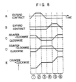
- Fig. 4 shows one form of the signal pattern applied from the channels CH 1 to CH 4 of the signal generator 302. In Fig. 4, this signal pattern is illustrated to have a rectangular waveform.
- Fig. 5 is a time chart showing how the piezoelectric elements 5, 6,11 and 12 operate with time T in response to the signal pattern shown in Fig. 4.
- Fig. 5 shows in A the time chart of operation of the piezoelectric element 5 and in B that of the piezoelectric element 6. In each of the curves in A and B, a positive portion indicates that an expansive strain occurs to release the shaft 2 from the clamped state, while a negative portion indicates that a contractive strain occurs to clamp the shaft 2.
- Fig. 5 shows in C the operating state of the piezoelectric elements 11, and in D that of the piezoelectric elements 12.
- a positive portion indicates that the piezoelectric elements 11 and 12 are deformed to cause counter-clockwise rotation of the piezoelectric elements 5 and 6 respectively, while a negative portion indicates that the piezoelectric elements 11 and 12 are deformed to cause clockwise rotation of the piezoelectric elements 5 and 6 respectively.
- Fig. 5 shows in E the angular displacement of the shaft 2 relative to the cylindrical body 1. In Fig. 5, all of the horizontal axes represent the time T, and CD to @ represent the sequential steps of operation.
- the piezoelectric element 6 expands to clamp the shaft 2, while the piezoelectric element 5 contracts to release the shaft 2 from the clamped state.
- the piezoelectric elements 12 are deformed to cause counter-clockwise rotation of the piezoelectric element 6 by one step, while, at the same time, the piezoelectric elements 11 are deformed to cause clockwise rotation of the piezoelectric element 5 by one step. Consequently, the shaft 2 is rotated counterclockwise by one step relative to the cylindrical body 1.
- the piezoelectric element 5 contracts to clamp the shaft 2.
- the piezoelectric element 6 expands to release the shaft 2 from the clamped state.
- the piezoelectric elements 11 are deformed to cause counter-clockwise rotation of the piezoelectric element 5 by one step, while, at the same time, the piezoelectric elements 12 are deformed to cause clockwise rotation of the piezoelectric element 6 by one step. Consequently, the shaft 2 is rotated counter-clockwise by one step relative to the cylindrical body 1.
- the piezoelectric element 6 contracts to clamp the shaft 2. This clamping exhibits a brake action holding the shaft 2 in its clamped state after the energizing voltage ceases to be applied.
- the shaft 2 can be rotated counter-clockwise continuously.
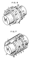
- Fig. 6 shows another embodiment of the rotary actuator according to the present invention, and the same reference numerals are used in Fig. 6 to designate the same parts appearing in Fig. 1.
- the second piezoelectric elements 11 and 12 of shearing strain type are replaced by piezoelectric elements 13 of bimorph type.
- a plurality of such piezoelectric elements 13 of bimorph type are disposed between the holding member 4 and the first piezoelectric elements 5, 6 so as to cause displacement of the piezoelectric elements 5, 6 in the circumferential direction.
- the amount of circumferential displacement of the piezoelectric elements 5 and 6 can be increased although the force generated by the piezoelectric elements 13 of bimorph type is small compared with the piezoelectric elements 11 and 12 of shearing strain type. Therefore, an actuator can be provided in which the rotor can be rotated at a higher speed.
- Fig. 7 shows still another embodiment of the rotary actuator according to the pressnt invention, and the same reference numerals are used in Fig. 7 to designate the same parts appearing in Fig. 1.
- the third embodiment is constructed so that the shaft 2 functions as the stator, and the cylindrical body 1 is rotatable relative to the shaft 2 to function as the rotor.
- the shaft 2 is provided with a holding member 14 for holding the second piezoelectric elements 11 and 12 coupled to the first piezoelectric elements 5 and 6 respectively. This holding member 14 extends from the shaft 2 toward the cylindrical body 1.
- the outer peripheral surface of the first piezoelectric elements 5 and 6 acts as a working surface engaged with and disengaged from the inner peripheral surface of the cylindrical body 1 to clamp and release the cylindrical body 1 when the first piezoelectric elements 5 and 6 are subjected to contraction and expansion.
- the operation of this third embodiment is similar to that of the embodiment shown in Fig. 1, and, therefore, any detailed description thereof is unnecessary. Since a piezoelectric body has generally a very strong resistance to a compressive stress than a tensile stress, the arrangement of the embodiment of Fig. 7 in which the first piezoelectric elements 5 and 6 are pressed against the inner periphery of the cylindrical body 1 for clamping is effective for improving the useful service life of the first piezoelectric elements 5 and 6.
- the second piezoelectric elements 11 and 12 may be replaced by the bimorph elements shown in Fig. 6. Further, the second piezoelectric elements 11 and 12 may be of a single layer structure or of a laminated structure having many electrodes.
- the second drive means are coupled to the side faces of the first drive means in the aforementioned embodiments, the present invention is in no way limited to such a coupling mode, and the second drive means may be coupled to the inner or outer periphery of the first drive means.
- the signal supplied from the signal generator in the drive circuit is in no way limited to the rectangular waveform signal described above, and an analog signal such as a sinusoidal waveform signal may be supplied.
- a plurality of rotary actuators as described above can be disposed in a relation juxtaposed in the axial direction.
- the present invention provides a rotary actuator which can continuously supply rotating torque and which is small in size, light in weight and compact in structure.
Landscapes
- General Electrical Machinery Utilizing Piezoelectricity, Electrostriction Or Magnetostriction (AREA)
Applications Claiming Priority (2)
| Application Number | Priority Date | Filing Date | Title |
|---|---|---|---|
| JP57184535A JPS5976184A (ja) | 1982-10-22 | 1982-10-22 | アクチユエ−タ |
| JP184535/82 | 1982-10-22 |
Publications (3)
| Publication Number | Publication Date |
|---|---|
| EP0112454A2 EP0112454A2 (en) | 1984-07-04 |
| EP0112454A3 EP0112454A3 (en) | 1986-12-10 |
| EP0112454B1 true EP0112454B1 (en) | 1989-03-01 |
Family
ID=16154893
Family Applications (1)
| Application Number | Title | Priority Date | Filing Date |
|---|---|---|---|
| EP83110520A Expired EP0112454B1 (en) | 1982-10-22 | 1983-10-21 | Rotary actuator |
Country Status (4)
| Country | Link |
|---|---|
| US (1) | US4468583A (ko) |
| EP (1) | EP0112454B1 (ko) |
| JP (1) | JPS5976184A (ko) |
| DE (1) | DE3379306D1 (ko) |
Families Citing this family (55)
| Publication number | Priority date | Publication date | Assignee | Title |
|---|---|---|---|---|
| US4622483A (en) * | 1983-03-24 | 1986-11-11 | Staufenberg Jr Charles W | Piezoelectric electromechanical translation apparatus and method |
| USRE34409E (en) * | 1983-05-04 | 1993-10-19 | Nikon Corporation | Drive circuit for surface-wave driven motor utilizing ultrasonic vibration |
| JPS59204477A (ja) * | 1983-05-04 | 1984-11-19 | Nippon Kogaku Kk <Nikon> | 超音波モーターの駆動制御回路 |
| JPS60118072A (ja) * | 1983-11-30 | 1985-06-25 | Toshiba Corp | 回転微動機構 |
| DE3474380D1 (en) * | 1984-05-03 | 1988-11-03 | Ibm | Piezoelectric stepping rotator |
| US4523120A (en) * | 1984-06-04 | 1985-06-11 | The United States Of America As Represented By The Secretary Of The Navy | Precise bearing support ditherer with piezoelectric drive means |
| JPH0614789B2 (ja) * | 1984-06-25 | 1994-02-23 | 株式会社東芝 | テーブル微動方法およびこの方法を用いた微動装置 |
| JPS6133397A (ja) * | 1984-07-26 | 1986-02-17 | 日本電気株式会社 | 宇宙航行体用動釣合調整装置 |
| JPS6162370A (ja) * | 1984-08-31 | 1986-03-31 | Tokyo Juki Ind Co Ltd | ピエゾモ−タ |
| DE3516324A1 (de) * | 1985-05-07 | 1986-11-13 | Vdo Adolf Schindling Ag, 6000 Frankfurt | Linearmotor |
| US4636679A (en) * | 1986-01-15 | 1987-01-13 | The United States Of America As Represented By The Secretary Of The Air Force | Piezoelectrically driven fast response high-torque clutch unit |
| JPS62293978A (ja) * | 1986-06-11 | 1987-12-21 | Canon Inc | 回転アクチエ−タ |
| DE3744239C1 (de) * | 1987-12-24 | 1989-06-01 | Heraeus Gmbh W C | Elektronisches Thermometer |
| JP2614635B2 (ja) * | 1988-04-12 | 1997-05-28 | 日立マクセル株式会社 | 電歪公転子及び単相超音波モータ |
| IL87312A (en) * | 1988-08-02 | 1992-02-16 | Zvi Orbach | Electromechanical translation apparatus of the inchworm linear motor type |
| US5043621A (en) * | 1988-09-30 | 1991-08-27 | Rockwell International Corporation | Piezoelectric actuator |
| US4928030A (en) * | 1988-09-30 | 1990-05-22 | Rockwell International Corporation | Piezoelectric actuator |
| US4874979A (en) * | 1988-10-03 | 1989-10-17 | Burleigh Instruments, Inc. | Electromechanical translation apparatus |
| US4968914A (en) * | 1989-03-24 | 1990-11-06 | Quanscan, Inc. | High resolution electromechanical translation device |
| US4987334A (en) * | 1989-08-15 | 1991-01-22 | Northrop Corporation | Piezoelectric dither motor |
| DE59008950D1 (de) * | 1989-12-16 | 1995-05-24 | Teldix Gmbh | Schrittmotor zum antrieb eines körpers, insbesondere einer welle, um kleine drehwinkel pro schritt. |
| CA2020185A1 (en) * | 1990-03-05 | 1991-09-06 | Gordon Walter Culp | Electrical drive for a segmented transducer |
| US5079471A (en) * | 1990-06-04 | 1992-01-07 | Martin Marietta Corporation | High torque harmonic traction motor |
| DE4023311A1 (de) * | 1990-07-21 | 1992-01-23 | Omicron Vakuumphysik | Verstellvorrichtung fuer mikrobewegungen |
| JPH04372324A (ja) * | 1991-06-21 | 1992-12-25 | Toyoda Mach Works Ltd | 送り装置 |
| EP0613586A1 (de) * | 1992-09-21 | 1994-09-07 | Hans Richter | Piezo-rotationsmotor |
| DE69318662T2 (de) * | 1992-10-02 | 1998-11-26 | Philips Electronics N.V., Eindhoven | Elektromechanische Verschiebevorrichtung und geeigneter Aktuator zur Verwendung in einer derartigen Verschiebevorrichtung |
| US5589723A (en) * | 1994-03-29 | 1996-12-31 | Minolta Co., Ltd. | Driving apparatus using transducer |
| US5626312A (en) * | 1994-07-06 | 1997-05-06 | Mcdonnell Douglas Corporation | Piezoelectric actuator |
| JPH0837784A (ja) * | 1994-07-25 | 1996-02-06 | Nikon Corp | 移動装置及び移動装置の制御方法 |
| US5751090A (en) * | 1995-05-17 | 1998-05-12 | Burleigh Instruments Inc | Peristaltic driver apparatus |
| RU2153219C2 (ru) * | 1996-06-03 | 2000-07-20 | Окатов Юрий Владимирович | Пьезоэлектрический шаговый двигатель |
| RU2156535C2 (ru) * | 1996-06-05 | 2000-09-20 | Окатов Юрий Владимирович | Пьезоэлектрический линейный шаговый двигатель |
| RU2161364C2 (ru) * | 1996-06-05 | 2000-12-27 | Окатов Юрий Владимирович | Пьезоэлектрический шаговый двигатель |
| RU2167487C2 (ru) * | 1996-06-05 | 2001-05-20 | Окатов Юрий Владимирович | Пьезоэлектрический шаговый двигатель |
| RU2167489C2 (ru) * | 1996-06-05 | 2001-05-20 | Окатов Юрий Владимирович | Пьезоэлектрический шаговый двигатель |
| RU2101840C1 (ru) * | 1996-06-10 | 1998-01-10 | Санкт-Петербургская государственная академия аэрокосмического приборостроения | Шаговый двигатель |
| RU2167486C2 (ru) * | 1996-06-05 | 2001-05-20 | Окатов Юрий Владимирович | Пьезоэлектрический шаговый двигатель |
| JP3456349B2 (ja) * | 1996-09-05 | 2003-10-14 | ミノルタ株式会社 | 電気機械変換素子を使用した回転型駆動装置 |
| FR2760578B1 (fr) * | 1997-03-06 | 1999-05-14 | Intertechnique Sa | Appareil piezo-electrique d'avance pas a pas |
| DE19712919C1 (de) * | 1997-03-27 | 1998-09-03 | Fraunhofer Ges Forschung | Antriebsvorrichtung zur Ausführung von Drehbewegungen |
| US5942838A (en) * | 1997-08-19 | 1999-08-24 | The Hong Kong University Of Science & Technology | Rotary motor driven by a piezoelectric composite laminate |
| DE19909913B4 (de) * | 1999-03-06 | 2004-01-15 | NMI Naturwissenschaftliches und Medizinisches Institut an der Universität Tübingen | Elektromechanische Antriebsvorrichtung |
| US6836056B2 (en) * | 2000-02-04 | 2004-12-28 | Viking Technologies, L.C. | Linear motor having piezo actuators |
| US6437226B2 (en) | 2000-03-07 | 2002-08-20 | Viking Technologies, Inc. | Method and system for automatically tuning a stringed instrument |
| US6548938B2 (en) | 2000-04-18 | 2003-04-15 | Viking Technologies, L.C. | Apparatus having a pair of opposing surfaces driven by a piezoelectric actuator |
| US6717332B2 (en) | 2000-04-18 | 2004-04-06 | Viking Technologies, L.C. | Apparatus having a support structure and actuator |
| SE0002884D0 (sv) | 2000-08-11 | 2000-08-11 | Piezomotor Uppsala Ab | Switched actuator control |
| US6879087B2 (en) | 2002-02-06 | 2005-04-12 | Viking Technologies, L.C. | Apparatus for moving a pair of opposing surfaces in response to an electrical activation |
| US6759790B1 (en) | 2001-01-29 | 2004-07-06 | Viking Technologies, L.C. | Apparatus for moving folded-back arms having a pair of opposing surfaces in response to an electrical activation |
| CN1663059A (zh) * | 2002-06-21 | 2005-08-31 | 瓦伊金技术有限公司 | 单体压电电动机 |
| US7368856B2 (en) | 2003-04-04 | 2008-05-06 | Parker-Hannifin Corporation | Apparatus and process for optimizing work from a smart material actuator product |
| DE102005052132B4 (de) * | 2005-10-28 | 2008-02-14 | Universität Hamburg | Piezoelektrische Bewegungseinrichtung |
| GB201214270D0 (en) * | 2012-08-09 | 2012-09-26 | Wilson Stephen A | A piezo-electric actuator and applications thereof |
| CN103671601A (zh) * | 2013-12-30 | 2014-03-26 | 潘永泰 | 用于分级破碎机上具有保护功能的拆装式传动装置 |
Family Cites Families (10)
| Publication number | Priority date | Publication date | Assignee | Title |
|---|---|---|---|---|
| DE1933205A1 (de) * | 1969-06-26 | 1971-01-07 | Siemens Ag | Mikroschritt-Motor |
| US3902084A (en) * | 1974-05-30 | 1975-08-26 | Burleigh Instr | Piezoelectric electromechanical translation apparatus |
| SU502426A1 (ru) * | 1974-07-18 | 1976-02-05 | Институт технической кибернетики | Ультразвуковой линейный шаговый двигатель |
| US3902085A (en) * | 1974-11-25 | 1975-08-26 | Burleigh Instr | Electromechanical translation apparatus |
| SE436675B (sv) * | 1975-08-12 | 1985-01-14 | Ki Politekhnichsky I Im 50 Let | Elektrisk motor driven genom piezoelektriska krafter |
| CA1066345A (en) * | 1975-08-29 | 1979-11-13 | Western Electric Company, Incorporated | Linear piezoelectric actuator with liner controlling frictional wear |
| SU604058A1 (ru) * | 1976-12-06 | 1978-04-25 | Каунасский Политехнический Институт Им.Антанаса Снечкуса | Вибродвигатель вращательного движени |
| US4219755A (en) * | 1977-03-18 | 1980-08-26 | Physics International Company | Electromotive actuator |
| SU771771A1 (ru) * | 1978-10-17 | 1980-10-15 | Московский институт электронной техники | Шаговый двигатель дл прецизионного перемещени |
| SU843032A1 (ru) * | 1979-08-09 | 1981-06-30 | Предприятие П/Я А-3771 | Пьезоэлектрический шаговый двигатель |
-
1982
- 1982-10-22 JP JP57184535A patent/JPS5976184A/ja active Granted
-
1983
- 1983-10-07 US US06/539,759 patent/US4468583A/en not_active Expired - Fee Related
- 1983-10-21 EP EP83110520A patent/EP0112454B1/en not_active Expired
- 1983-10-21 DE DE8383110520T patent/DE3379306D1/de not_active Expired
Also Published As
| Publication number | Publication date |
|---|---|
| EP0112454A2 (en) | 1984-07-04 |
| JPS5976184A (ja) | 1984-05-01 |
| DE3379306D1 (en) | 1989-04-06 |
| EP0112454A3 (en) | 1986-12-10 |
| JPH0124033B2 (ko) | 1989-05-09 |
| US4468583A (en) | 1984-08-28 |
Similar Documents
| Publication | Publication Date | Title |
|---|---|---|
| EP0112454B1 (en) | Rotary actuator | |
| US5144187A (en) | Piezoelectric motor | |
| US6982502B1 (en) | Hybrid electric linear actuator | |
| US5027028A (en) | Piezoelectric motor | |
| JPH0528071B2 (ko) | ||
| US20020005681A1 (en) | Smart material motor with mechanical diodes | |
| KR100575596B1 (ko) | 압전 모터 | |
| JP2001145379A (ja) | 光アクチュエータ | |
| US5530312A (en) | Multi-cycle electric motor system | |
| KR100353457B1 (ko) | 압전형스텝모터 | |
| JPH06233557A (ja) | 超音波モータ | |
| WO2012165189A1 (ja) | 圧電モータおよび圧電モータ装置 | |
| JPS62247769A (ja) | 超音波モ−タ | |
| CN112713805B (zh) | 一种基于压电叠堆的旋转驱动装置 | |
| JPH0453193Y2 (ko) | ||
| CN112290823B (zh) | 基于螺旋嵌位结构的直线压电作动器及其工作方法 | |
| CN111146971B (zh) | 一种夹心式多模态复合型旋转压电作动器及其工作方法 | |
| SU711305A1 (ru) | Электрогидравлический усилитель дискретного действи | |
| JPH05328752A (ja) | 直線アクチュエータ | |
| JPH01298968A (ja) | 超音波モータ | |
| CN211606421U (zh) | 一种柔性薄膜直线电机 | |
| SU1399863A2 (ru) | Волновой электродвигатель | |
| JPS6376923A (ja) | 圧電クラツチ | |
| JP2760148B2 (ja) | 振動アクチュエータの駆動制御装置 | |
| CN114401831A (zh) | 固态刹车机构及包括该固态刹车机构的机器人 |
Legal Events
| Date | Code | Title | Description |
|---|---|---|---|
| PUAI | Public reference made under article 153(3) epc to a published international application that has entered the european phase |
Free format text: ORIGINAL CODE: 0009012 |
|
| AK | Designated contracting states |
Designated state(s): CH DE FR GB IT LI SE |
|
| PUAL | Search report despatched |
Free format text: ORIGINAL CODE: 0009013 |
|
| RHK1 | Main classification (correction) |
Ipc: H01L 41/08 |
|
| AK | Designated contracting states |
Kind code of ref document: A3 Designated state(s): CH DE FR GB IT LI SE |
|
| 17P | Request for examination filed |
Effective date: 19861212 |
|
| 17Q | First examination report despatched |
Effective date: 19880511 |
|
| GRAA | (expected) grant |
Free format text: ORIGINAL CODE: 0009210 |
|
| AK | Designated contracting states |
Kind code of ref document: B1 Designated state(s): CH DE FR GB IT LI SE |
|
| REF | Corresponds to: |
Ref document number: 3379306 Country of ref document: DE Date of ref document: 19890406 |
|
| ET | Fr: translation filed | ||
| ITF | It: translation for a ep patent filed | ||
| PLBE | No opposition filed within time limit |
Free format text: ORIGINAL CODE: 0009261 |
|
| STAA | Information on the status of an ep patent application or granted ep patent |
Free format text: STATUS: NO OPPOSITION FILED WITHIN TIME LIMIT |
|
| 26N | No opposition filed | ||
| ITTA | It: last paid annual fee | ||
| PGFP | Annual fee paid to national office [announced via postgrant information from national office to epo] |
Ref country code: SE Payment date: 19920902 Year of fee payment: 10 |
|
| PGFP | Annual fee paid to national office [announced via postgrant information from national office to epo] |
Ref country code: CH Payment date: 19921229 Year of fee payment: 10 |
|
| PG25 | Lapsed in a contracting state [announced via postgrant information from national office to epo] |
Ref country code: SE Effective date: 19931022 |
|
| PG25 | Lapsed in a contracting state [announced via postgrant information from national office to epo] |
Ref country code: LI Effective date: 19931031 Ref country code: CH Effective date: 19931031 |
|
| REG | Reference to a national code |
Ref country code: CH Ref legal event code: PL |
|
| EUG | Se: european patent has lapsed |
Ref document number: 83110520.0 Effective date: 19940510 |
|
| REG | Reference to a national code |
Ref country code: GB Ref legal event code: IF02 |
|
| PGFP | Annual fee paid to national office [announced via postgrant information from national office to epo] |
Ref country code: FR Payment date: 20020923 Year of fee payment: 20 |
|
| PGFP | Annual fee paid to national office [announced via postgrant information from national office to epo] |
Ref country code: GB Payment date: 20020926 Year of fee payment: 20 |
|
| PGFP | Annual fee paid to national office [announced via postgrant information from national office to epo] |
Ref country code: DE Payment date: 20021205 Year of fee payment: 20 |
|
| PG25 | Lapsed in a contracting state [announced via postgrant information from national office to epo] |
Ref country code: GB Free format text: LAPSE BECAUSE OF EXPIRATION OF PROTECTION Effective date: 20031020 |
|
| REG | Reference to a national code |
Ref country code: GB Ref legal event code: PE20 |